Installation Instructions - Chris Alston's Chassisworks
Installation Instructions - Chris Alston's Chassisworks
Installation Instructions - Chris Alston's Chassisworks

You also want an ePaper? Increase the reach of your titles
YUMPU automatically turns print PDFs into web optimized ePapers that Google loves.
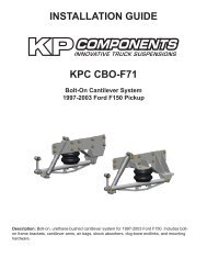
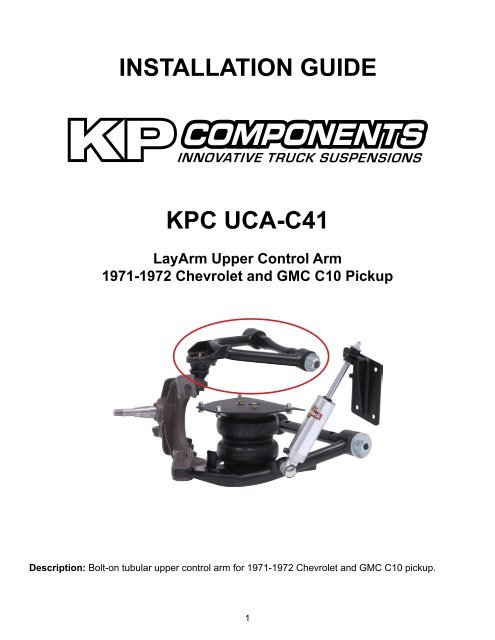
INSTALLATION GUIDE<br />
KPC UCA-C41<br />
LayArm Upper Control Arm<br />
1971-1972 Chevrolet and GMC C10 Pickup<br />
Description: Bolt-on tubular upper control arm for 1971-1972 Chevrolet and GMC C10 pickup.<br />
1
PARTS LIST<br />
KPC UCA-C41 - LayArm Upper Control Arms, ‘71-72 C10<br />
Qty Part Number Description<br />
1 7936-022 LayArm air-bag upper control arm assembly, driver side 71-72 C10<br />
1 7936-023 LayArm air-bag upper control arm assembly, passenger side 71-72 C10<br />
7926-UCAC41 - Hardware Bag<br />
Qty Part Number Description<br />
4 3101-050-20C Locknut 1/2-20 nylon insert<br />
4 3120-050S-Y Washer 1/2 SAE hardened flat<br />
We recommend you refer to the factory service manual for more detailed disassembly instructions.<br />
1. Raise the truck to a safe comfortable working height.<br />
2. Place jack stands under the frame and let the front suspension hang.<br />
3. Remove the front wheels.<br />
INSTRUCTIONS<br />
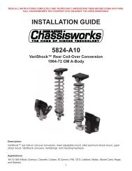
4. Place a floor jack under the lower control arm to hold it up once the lower balljoint is loosened at the<br />
spindle. Do not support the weight of the vehicle with the floor jack.<br />
5. Remove the cotter pin and castle nut from the upper balljoint.<br />
6. Use a balljoint separator or pickle fork, to separate the upper balljoint from the spindle. A large hammer can<br />
also be used to strike the spindle, jarring the balljoint stud loose.<br />
7. Once the balljoint is loose, raise the control arm up and out of the way.<br />
8. Remove the locknuts that secure the pivot shaft. Save all the alignment shims and the cross shaft spacers.<br />
2
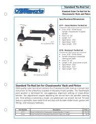
9. Slide the driver side upper control arm over<br />
the studs. Do not place any alignment shims<br />
between the spacer and the cross shaft at this<br />
time.<br />
10. Put two 1/2” hardened flat washer on the<br />
studs followed by the locknuts and tighten the<br />
locknuts.<br />
11. Lower the upper control arm and insert the<br />
balljoint stud into the spindle.<br />
12. Thread the castle nut onto the balljoint stud and<br />
tighten. Torque to 75 lb.-ft.<br />
13. Align the slot in the castle nut with the balljointstud<br />
. Insert the cotter pin into the stud and<br />
wrap around the castle nut as shown.<br />
14. Move the system throughout the complete<br />
range of travel to check for binding and proper<br />
clearance around the air bag. A minimum of<br />
3/4” clearance around the air bag is required to<br />
operate safely once inflated.<br />
15. Repeat this for the passenger side of the truck.<br />
3
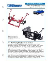
Preload the Control Arm Bushings<br />
16. After the upper and lower control arms,<br />
spindles, and shocks have been installed,<br />
use a floor jack at the lower arm to raise the<br />
suspension to it’s ride-height position; normally<br />
center of shock travel.<br />
17. The locknuts on the control arms can now be<br />
fully tightened to preload the bushings.<br />
18. You will need to have the front end aligned<br />
before driving the truck.<br />
WARRANTY NOTICE:<br />
There are NO WARRANTIES, either expressed or implied. Neither the seller nor manufacturer will be liable for any loss, damage<br />
or injury, direct or indirect, arising from the use or inability to determine the appropriate use of any products. Before any attempt<br />
at installation, all drawings and/or instruction sheets should be completely reviewed to determine the suitability of the product for<br />
its intended use. In this connection, the user assumes all responsibility and risk. We reserve the right to change specification<br />
without notice. Further, <strong>Chris</strong> Alston’s <strong>Chassisworks</strong>, Inc., makes NO GUARANTEE in reference to any specific class legality of any<br />
component. ALL PRODUCTS ARE INTENDED FOR RACING AND OFF-ROAD USE AND MAY NOT BE LEGALLY USED ON THE<br />
HIGHWAY. The products offered for sale are true race-car components and, in all cases, require some fabrication skill. NO PRODUCT<br />
OR SERVICE IS DESIGNED OR INTENDED TO PREVENT INJURY OR DEATH.<br />
KP Components<br />
A <strong>Chris</strong> Alston’s <strong>Chassisworks</strong> Inc., Brand<br />
8661 Younger Creek Drive<br />
Sacramento, CA 95828<br />
Technical Support: KPtech@cachassisworks.com<br />
7927-UCAC41 REV 08/24/09<br />
4