
You also want an ePaper? Increase the reach of your titles
YUMPU automatically turns print PDFs into web optimized ePapers that Google loves.
2<br />
Het Bijvank 251a, 7544 DB Enschede, The Netherlands<br />
P.O. Box 40175, 7504 RD Enschede, The Netherlands<br />
Phone: +31 53 4762619 Fax: +31 53 4771905<br />
E-mail: info@humeca.nl Web: www.humeca.nl<br />
General remark<br />
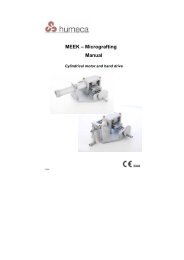
<strong>Automatic</strong> <strong>MEEK</strong> <strong>–</strong> <strong>machine</strong><br />
Instructions for mounting and dismounting<br />
This booklet only describes how the automatic (two axis driven)<br />
<strong>MEEK</strong> Micrograft <strong>machine</strong> is mounted, dismounted and used.<br />
Basic knowledge on the use of the <strong>MEEK</strong> technique (equipment<br />
and procedure) is supposed to be present already.<br />
This instruction focuses at differences in handling compared to<br />
the conventional <strong>machine</strong>s.<br />
AUT/11-07
Contents<br />
3<br />
I. The basic parts of the automatic <strong>machine</strong><br />
4<br />
I. The basic parts of the automatic <strong>machine</strong> 4<br />
II. Assembling the <strong>machine</strong><br />
II-1. Placing the pneumatic motors 5<br />
I-1a. Placing the motor for drive of the cutting axis 5<br />
I-1b. Placing the motor for drive of the spindle 7<br />
II-2. Connecting the air hoses for pneumatic drive 8<br />
III. Using the <strong>machine</strong> 10<br />
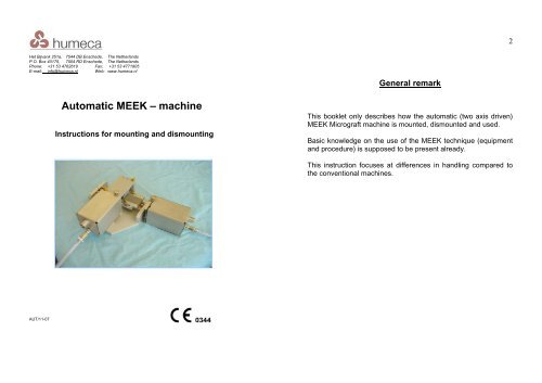
Fig. 1 The basic parts of the automatic <strong>MEEK</strong> <strong>machine</strong><br />
The automatic <strong>MEEK</strong> <strong>machine</strong> consists of the following main parts:<br />
1 The frame with cutting block (single or double)<br />
2 Two identical stainless steel motor housings<br />
3 A pneumatic motor to drive the spindle<br />
4 A pneumatic motor driving the cutting axis (the picture<br />
shows a block motor, but the motor might also be one of<br />
the cylindrical type).<br />
5 A foot pedal (not shown in the picture)<br />
6 A splitted hose with 3 connectors (not shown either).<br />
Attention: The motors are not to be sterilized!!
II. Assembling the <strong>machine</strong><br />
5<br />
6<br />
II-1. Placing the pneumatic motors<br />
A new automatic <strong>MEEK</strong> <strong>machine</strong> is provided with two motors.<br />
However, if your existing motor driven <strong>machine</strong> was modified to an<br />
automatic model, probably your original motor was suitable to reuse<br />
it to drive the cutting axis.<br />
Fig. 3. The motor is placed in the<br />
motor housing<br />
Fig. 4. The motor in correct position<br />
in its housing<br />
Fig. 2. the two motors that are supplied in case of a new <strong>machine</strong><br />
Fig. 2 shows both motors of a new <strong>machine</strong>. Please note that the<br />
couplings of the motors (the round plastic parts) are not the same<br />
size. The motor with the smallest coupling is the one for drive of<br />
the cutting axis; the other motor will drive the spindle (movement of<br />
the cutting block). The two motor housings are identical.<br />
Now place the casing with the motor inside on the <strong>machine</strong> in a<br />
way that the two screws 10 slide into the two slits 3a at the<br />
bottom side of the casing (marked with red colour in fig. 5).<br />
Push the plastic coupling of the motor over the corresponding<br />
metal coupling of the knives axis and push further until the<br />
screw 9 comes into the slot 3b of the casing (fig. 6). Fasten<br />
screw 9 by hand (fig. 7).<br />
Attention: prevent the motor from falling out of the casing!<br />
II-1a. Placing the motor for drive of the cutting axis<br />
This procedure is not different from the one already known:<br />
See fig. 3 and 4. A circulating nurse places the unsterile motor<br />
into the sterile casing, which is held in position by authorized<br />
personnel. The motor is placed in the casing in such a way that<br />
the sound reducer (the cylinder with porous material at the back<br />
of the motor) comes in the little pipe at the back of the casing.<br />
Fig. 5. The screws 10 must slide<br />
into the slits 3a<br />
Fig. 6. Placing the motor for drive of<br />
the cutting axis on the <strong>machine</strong>
7<br />
8<br />
Fig. 7. Fixing the motor housing with motor inside to the <strong>machine</strong><br />
II-1b. Placing the motor for drive of the spindle<br />
Put the motor with the larger coupling in the second motor<br />
housing (procedure same as shown in fig. 3 and 4). Push the<br />
plastic coupling of the motor over the corresponding metal<br />
coupling of the spindle axis and push further until the screw 9a<br />
comes into the slot 3b of the casing (fig. 8 and 9). Fasten screw<br />
9a (fig. 10).<br />
Fig. 10. Fixing the motor housing with motor inside to the <strong>machine</strong><br />
II-2. Connecting the air hoses for pneumatic drive<br />
The automatic <strong>MEEK</strong> <strong>machine</strong> was supplied with a hose with Y-<br />
crossing and 3 connectors. Two connectors are identical and<br />
one is different. Connect the 2 identical connectors to the two<br />
motors of the <strong>machine</strong> (simply push the connectors over the<br />
motor inlets, as shown in fig. 11).<br />
Fig. 8. Placing the motor for driving<br />
the spindle axis on the <strong>machine</strong><br />
Fig. 9. Motor in correct position<br />
Fig. 11. Coupling the<br />
hose to the motor
9<br />
The foot pedal has two connections. One hose is already fixed<br />
to a connection. Connect the other end of that hose to the third<br />
connector of the hose supplied with the <strong>machine</strong> (fig. 12).<br />
III. Using the <strong>machine</strong><br />
After having filled the cutting block with a cork plate and graft, put<br />
the block on the <strong>machine</strong> at the side of the motor that will drive the<br />
spindle. Now press the foot pedal. You will notice that the block will<br />
not move instantly. This is for safety reasons. The block will start<br />
running after you push it a little in the direction of movement while<br />
pressing the foot pedal (see fig. 14).<br />
10<br />
Fig. 12. Coupling the hose of the <strong>machine</strong> to the hose of<br />
the foot pedal<br />
Connect the inlet of the foot pedal to the pressure air outlet in<br />
the operating theatre. Because there is a large variety in hose<br />
diameters and connectors in use at hospitals, we cannot supply<br />
the air hose between the foot pedal and the pressure system in<br />
the operating room. Please arrange a suitable hose for that<br />
purpose yourself. We’re happy to assist you if necessary. A<br />
pressure of 5-6 bar is required to run the motors.<br />
The apparatus is now ready<br />
for use (fig. 13). Lubricate<br />
the <strong>machine</strong> as usual.<br />
For dismounting the<br />
<strong>machine</strong>, you act in reverse<br />
order.<br />
Fig. 14. For safety reasons the block will only move after a<br />
gentle push<br />
When the block reaches the other side of the <strong>machine</strong>, it will stop<br />
automatically. Please take it off and go ahead with a second block<br />
if you like. Of course the cutting procedure is speeded up when<br />
two blocks are used, especially if both blocks are double blocks.<br />
Fig. 13. <strong>Automatic</strong> <strong>MEEK</strong><br />
<strong>machine</strong> after assemblage