User manual in English - Humeca
User manual in English - Humeca
User manual in English - Humeca
- No tags were found...

Create successful ePaper yourself
Turn your PDF publications into a flip-book with our unique Google optimized e-Paper software.
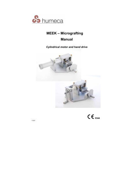
MEEK – Micrograft<strong>in</strong>gManualCyl<strong>in</strong>drical motor and hand drive11/01
General remarkThis <strong>manual</strong> describes how the MEEK technique is performed <strong>in</strong> textand pictures.For a better understand<strong>in</strong>g of the procedure we strongly advise youto watch the MEEK <strong>in</strong>struction films that comes with each mach<strong>in</strong>e.These films clearly show the MEEK procedure, from assembly of themach<strong>in</strong>e until heal<strong>in</strong>g of the burn wound.Additional copies of the DVD are available from <strong>Humeca</strong> or your localdealer.Warn<strong>in</strong>g:Always pay attention to the presence of very sharp blades <strong>in</strong> theMEEK mach<strong>in</strong>e. Please handle them with care to prevent cutt<strong>in</strong>gaccidents!
Contents3I. Mount<strong>in</strong>g and dismount<strong>in</strong>g the mach<strong>in</strong>e1. Assembly of the mach<strong>in</strong>e 41a. Plac<strong>in</strong>g the pneumatic motor 41b. Connect<strong>in</strong>g the air hoses for pneumatic drive 51c. Plac<strong>in</strong>g the hand drive 52. Lubrication 53. Sterilization and clean<strong>in</strong>g 6II.The Micrograft-procedure1. Determ<strong>in</strong><strong>in</strong>g the expansion factor 82. Harvest<strong>in</strong>g the graft 83. Prepar<strong>in</strong>g the sk<strong>in</strong> before cutt<strong>in</strong>g 94. Plac<strong>in</strong>g the cork with the graft <strong>in</strong>to the cutt<strong>in</strong>g block 95. Cutt<strong>in</strong>g 105a The first cutt<strong>in</strong>g 105b The second cutt<strong>in</strong>g 106. Apply<strong>in</strong>g adhesive to the autograft 117. Transferr<strong>in</strong>g the graft to the gauze 118. Extend<strong>in</strong>g the gauze 129. Remov<strong>in</strong>g the fabric from the wound 1210. Local therapy 1311. Trouble shoot<strong>in</strong>g 14III. Service 18IV. Order<strong>in</strong>g 19V. Supplier 20Pictures 21-33
4I. Mount<strong>in</strong>g and dismount<strong>in</strong>g the mach<strong>in</strong>eSee fig. 1 and 2. The mach<strong>in</strong>e consists of a cutt<strong>in</strong>g block 1, aframe 2 and a pneumatic motor <strong>in</strong> a cyl<strong>in</strong>drical cas<strong>in</strong>g 3, or ahand drive. Rotation of a handwheel 4 causes the cutt<strong>in</strong>g block 1to move under a bridge 12 where 13 circular blades cut throughthe sk<strong>in</strong>.Attention: Do not sterilize the motor !!1. Assembly of the mach<strong>in</strong>eCheck whether the blades axis 10 is <strong>in</strong> its right position, asshown <strong>in</strong> fig. 2: the bear<strong>in</strong>gs should be <strong>in</strong> their seats and thecoupl<strong>in</strong>g 15 should po<strong>in</strong>t to the left side, when fac<strong>in</strong>g thehandwheel side of the mach<strong>in</strong>e. Place the bridge cover 12 (fig.1) on the frame and fasten the bolts 11 by hand.1a. Plac<strong>in</strong>g the pneumatic motorThe procedure to be followed for placement of the motor on themach<strong>in</strong>e is illustrated <strong>in</strong> fig. 3-9.Because the motor is not sterilized, it is encapsulated <strong>in</strong> a sterilecyl<strong>in</strong>drical cas<strong>in</strong>g (fig. 3). A circulat<strong>in</strong>g nurse places the unsterilemotor 22 <strong>in</strong>to the sterile cas<strong>in</strong>g 3, that is held <strong>in</strong> position byauthorized personnel. The motor is placed <strong>in</strong> the cas<strong>in</strong>g <strong>in</strong> sucha way that the cam 22a comes <strong>in</strong> the groove of the cas<strong>in</strong>g, asshown <strong>in</strong> fig. 4 and 5. Now place the cas<strong>in</strong>g with the motor<strong>in</strong>side on the mach<strong>in</strong>e and push the coupl<strong>in</strong>g hull 15a of themotor over the coupl<strong>in</strong>g hub 15 of the blades axis (fig. 6). See toit that the cas<strong>in</strong>g 3 fits precisely <strong>in</strong> the groove 14 of the bridge.The hole 3a <strong>in</strong> the cyl<strong>in</strong>drical wall of the cas<strong>in</strong>g should be at theupper side (fig. 7). Close the clamp 10. The cam 10a of theclamp should come <strong>in</strong>to the hole 3a of the cas<strong>in</strong>g wall (fig. 8). Ifclamp 10 cannot be closed, either the hole 3a is not <strong>in</strong> the rightposition, or the cas<strong>in</strong>g 3 is not pushed <strong>in</strong>to the groove 14 of thebridge. After clos<strong>in</strong>g clamp 10, fasten motor bolt 9 (fig. 9; pushand turn a quarter). The motor is taken off by act<strong>in</strong>g the otherway round.
5Attention:Beware that the motor doesn’t fall out of the cas<strong>in</strong>g!1b. Connect<strong>in</strong>g the air hoses for pneumatic driveThe procedure is illustrated <strong>in</strong> fig. 10-14.The foot pedal has two connections (fig. 10). One air hose isalready fastened to a connection. Connect the other end of thathose to the motor <strong>in</strong>let 22b by push<strong>in</strong>g the quick connector 8over it (fig. 11 and 12). Because there is a large variety <strong>in</strong> hosediameters and connectors <strong>in</strong> use at hospitals <strong>in</strong>ternationally, wecannot supply the air hose between the foot pedal and thepressure system <strong>in</strong> the operat<strong>in</strong>g room. Please arrange asuitable hose for that purpose yourself. We’re happy to assistyou if necessary. It is also possible to use an air cyl<strong>in</strong>der <strong>in</strong>steadof the wall outlet. Connect the hose from your pressure systemto the other connection of the foot pedal by means of quickconnector 24; see fig. 13. This quick connector is fixed to thehose with a hose-clamp. Connector and hose-clamps of differentsizes are supplied with the mach<strong>in</strong>e. See fig. 14 for <strong>in</strong>struction. Apressure of about 6 bars is recommended. Do not exceed 8bars. The apparatus is now ready for use.1c. Plac<strong>in</strong>g the hand driveThe procedure for plac<strong>in</strong>g the hand drive on the mach<strong>in</strong>e isillustrated <strong>in</strong> fig. 15-17.Place the coupl<strong>in</strong>g hull 15a of the hand drive over the coupl<strong>in</strong>ghub 15 of the blades axis and place the white polymer disk 20 <strong>in</strong>the opened cyl<strong>in</strong>drical support (fig. 15). The hole 20a <strong>in</strong> the diskshould be at the upper side. When clos<strong>in</strong>g clamp 10, the cam10a should come <strong>in</strong>to the hole of the disk (fig. 16). Fasten bolt 9(push and turn a quarter, fig. 17). The hand drive is taken off byact<strong>in</strong>g the other way round.2. LubricationTo grease the bear<strong>in</strong>gs of the blades axis and sp<strong>in</strong>dle werecommend to put a drop of oil <strong>in</strong>to the holes <strong>in</strong>dicated with ared circle <strong>in</strong> fig. 19. Also put a drop of oil on the half nut at theunderside of the cutt<strong>in</strong>g block (fig. 18). In case of pneumaticdrive, we also advise to put a drop of oil <strong>in</strong>to the <strong>in</strong>let of the
6motor once every 3 months. <strong>Humeca</strong> supplies AesculapSTERILIT ® oil for that purpose.3. Sterilization and clean<strong>in</strong>gTake out the motor. Beware that it doesn’t fall out of the cas<strong>in</strong>g!Attention: Never sterilize the motor !!The entire Micrograft cutt<strong>in</strong>g mach<strong>in</strong>e can be cleaned and steamsterilized, except for the motor. Autoclav<strong>in</strong>g occurs at a commontemperature of 134 o C (usually 5-10 m<strong>in</strong>utes) or 121 o C(prolonged exposure time of approx. 20 m<strong>in</strong>utes).If necessary, clean the blades by hand from sk<strong>in</strong> remnants andblood immediately after use. To that end loose the two screws11 (fig. 1) and lift off the cover 12 of the bridge. Take out theblades axis, clean it with water and a soft brush and replace it <strong>in</strong>the mach<strong>in</strong>e.Attention!!!Never touch the blades with your f<strong>in</strong>gers!They are extremely sharp. Never touch theblades with some hard object nor place themon a hard surface. They’ll be damaged.Also the <strong>in</strong>side of the cutt<strong>in</strong>g block cover has to be cleaned byhand sometimes. Because this surface contacts the sk<strong>in</strong> dur<strong>in</strong>gcutt<strong>in</strong>g, on the long term a sticky layer (biofilm) might be formed.If persistent, this layer has to be removed mechanically by hand.Fig. 20and 20A show how the different parts of the MEEKmach<strong>in</strong>e can be placed <strong>in</strong> the MEEK sterilization case 3.MAC02.If you use a different case, please leave the blades axis <strong>in</strong>position on the mach<strong>in</strong>e dur<strong>in</strong>g wash<strong>in</strong>g and sterilization (asshown <strong>in</strong> fig. 2) <strong>in</strong> order to prevent damage. Alternatively, youcan put the blades axis separately <strong>in</strong> the small sterilization case3.MAC03 (fig. 21) that <strong>Humeca</strong> supplies for this purpose. Thecutt<strong>in</strong>g block 1 and the serrated wedge 17 are placed next to themach<strong>in</strong>e dur<strong>in</strong>g sterilization.
Some additional remarks regard<strong>in</strong>g clean<strong>in</strong>g andsterilizationThe MEEK mach<strong>in</strong>e consists of anodised alum<strong>in</strong>ium andsta<strong>in</strong>less steel. The least damage to coloured and non-colouredanodised alum<strong>in</strong>ium is observed when neutral clean<strong>in</strong>g agentsare used <strong>in</strong> comb<strong>in</strong>ation with dem<strong>in</strong>eralised water. The quality ofwater <strong>in</strong> the clean<strong>in</strong>g process is of crucial importance. Anunfavourable water composition can have a detrimental effect onthe materials of surgical <strong>in</strong>struments.Strong alkal<strong>in</strong>e clean<strong>in</strong>g agents will cause visible changes to thesurface of the <strong>in</strong>strument, like sta<strong>in</strong>s and color fad<strong>in</strong>g.Hot air dry<strong>in</strong>g temperatures higher than 90 o C should be avoidedto prevent craz<strong>in</strong>g of the anodized surface. Do not use H 2 O 2(hydrogen peroxide) <strong>in</strong> the wash<strong>in</strong>g process, as it will damagethe <strong>in</strong>strument.A recommended procedure for clean<strong>in</strong>g and sterilization andadvisory on clean<strong>in</strong>g agents to be used is presented <strong>in</strong> a jo<strong>in</strong>tpublication of <strong>Humeca</strong> and Johnson Diversey. It is provided witheach <strong>in</strong>strument and available on request. You can alsodownload it from www.humeca.nl/downloads.7
II. The Micrograft-procedure81. Determ<strong>in</strong><strong>in</strong>g the expansion factorBefore harvest<strong>in</strong>g the autograft from the patient, the expansionfactor is determ<strong>in</strong>ed.In low- and medium-sized burns, there is no lack of donor sitesand thus no large expansion is required. In these cases anexpansion factor of 1:3 or 1:4 is enough for quickepithelialisation. In extensive burns however, the 1:6 expansionis recommended and only <strong>in</strong> extreme cases of very high TBSAburns a 1:9 expansion is required.Compared to meshgrafts the quantity of graft required <strong>in</strong> theMEEK technique is about half as much. Once the expansionfactor is determ<strong>in</strong>ed, the total donor site area can be roughlycalculated and the graft is taken from the patient.The expansion factor is clearly pr<strong>in</strong>ted on the peel pouch of eachgauze and it is also <strong>in</strong>dicated on the gauze itself (<strong>in</strong> one of thecorners the expansion 3, 4, 6 or 9 is relief- pr<strong>in</strong>ted <strong>in</strong> thealum<strong>in</strong>ium foil).2. Harvest<strong>in</strong>g the graftBefore harvest<strong>in</strong>g the graft, the sk<strong>in</strong> of the patient is oftengreased with some oil to enable a smooth run of the dermatomeover the sk<strong>in</strong>. However you should not to do this when us<strong>in</strong>g theMEEK technique, because the oil prevents good adhesion of thegraft islands to the fabric. Use water or buffered salt solution<strong>in</strong>stead, so:Attention!! When apply<strong>in</strong>g the MEEK technique, don’tuse oil or any other fatty substance whenharvest<strong>in</strong>g the graft from the patient !!
3. Prepar<strong>in</strong>g the sk<strong>in</strong> before cutt<strong>in</strong>g9In the MEEK technique the expansion is realized by means of apre-folded gauze (fig. 21). Each gauze is supplied with a corkplate measur<strong>in</strong>g 42x42 mm (1.65x1.65”) (fig. 22) and packedsterile <strong>in</strong> a peel pouch. Take the cork plate out of the pouch andsubmerge it <strong>in</strong>to water shortly. The cork plate now has to becovered with a piece of split sk<strong>in</strong> graft of the patient with thedermal side fac<strong>in</strong>g the cork. To this end spread a strip of splitsk<strong>in</strong> graft, epidermal side down, on a smooth surface, like aplasticized sterile cloth or the smooth side of a meshgraft carrier.Then place the cork plate on the graft and trim the graft to thesize of the cork plate. The MEEK-video clearly shows how this isdone <strong>in</strong> practice. If the graft strip was harvested with the<strong>Humeca</strong> D42 dermatome, the width of the strip equals the widthof the cork plate, which makes it much easier to cover it. Thecork plate covered with graft is shown <strong>in</strong> fig. 23. Smaller graftremnants can also be used by plac<strong>in</strong>g them on the cork platelike a "puzzle" (fig. 24), so there is no spillage of graft, which isan advantage <strong>in</strong> case of extensive burns.Attention!! The autograft should be trimmed to thesize of the cork plate. It should not belarger than the cork plate!4. Plac<strong>in</strong>g the cork with the graft <strong>in</strong>to the cutt<strong>in</strong>gblock.Place the cork square on the cork holder 18 and put it <strong>in</strong> therecess of the bottom of the cutt<strong>in</strong>g block (fig. 25). Moisten theunderside of the cover with water or buffered salt solution toprevent stick<strong>in</strong>g of the graft to the cover after cutt<strong>in</strong>g. Close thecover and lock with bolts 19, see fig. 26.
5. Cutt<strong>in</strong>g105a The first cutt<strong>in</strong>gPlace the cutt<strong>in</strong>g block on the guid<strong>in</strong>g axes of the cutt<strong>in</strong>gmach<strong>in</strong>e at the side of the handwheel (fig. 27). This can only bedone <strong>in</strong> one way because the guid<strong>in</strong>g axes differ <strong>in</strong> diameter.- In case pneumatic drive is used:Switch on the motor with the foot pedal and turn thehandwheel. The cutt<strong>in</strong>g block is now moved under the bridgewhere the rotat<strong>in</strong>g 13 blades cut the graft <strong>in</strong>to 14 stripes.- In case hand drive is used:Turn the handle of the hand drive clockwise while someoneelse turns the handwheel to move the cutt<strong>in</strong>g block under thebridge.Attention!!Always move the cutt<strong>in</strong>g block from the sideof the handwheel to the other side; neverreverse (fig. 27).When the cutt<strong>in</strong>g block has reached the end of the guid<strong>in</strong>g axesit can easily be taken off from the mach<strong>in</strong>e. Open the bolts 19,and place the serrated wedge 17 <strong>in</strong> the middle of the grat<strong>in</strong>g <strong>in</strong>the cover (fig. 28). Now push the serrated wedge downwards,while lift<strong>in</strong>g up the cover a little (fig. 29). Open the cover (fig. 30).The graft should rema<strong>in</strong> on the cork plate.In case a double cutt<strong>in</strong>g block (fig. 31) is used, the serratedwedge is pressed <strong>in</strong>to both grat<strong>in</strong>gs before open<strong>in</strong>g the cover.5b The second cutt<strong>in</strong>gTurn the cork holder (18) a quarter and put it back <strong>in</strong> the cutt<strong>in</strong>gblock. Moisten the underside of the cover aga<strong>in</strong>, close it and lockit. Put the cutt<strong>in</strong>g block on the guid<strong>in</strong>g axes at the side of thehandwheel once aga<strong>in</strong> and switch on the motor or start turn<strong>in</strong>gthe hand drive. Now the cutt<strong>in</strong>g block is passed under the bridgeonce more, and the graft is cut <strong>in</strong>to 14x14 = 196 squares. Openthe cutt<strong>in</strong>g block, us<strong>in</strong>g the serrated wedge as mentioned beforeto prevent stick<strong>in</strong>g of the graft to the cover and take out the corkplate with the graft (shown <strong>in</strong> fig. 32).
116. Apply<strong>in</strong>g adhesive to the autograftPlace the cork square with the cut autograft on a flat surfacecovered with a sterile cloth or some other disposable material.Spray glue on the epidermal side of the graft from a distance ofabout 25 cm (10 <strong>in</strong>ches) and allow to dry for at least 6 m<strong>in</strong>utes(the surface must change from glossy to dull). A longer dry<strong>in</strong>gtime does not harm.Attention!!- Allow the glue to dry for at least 6 m<strong>in</strong>utes!(some more dry<strong>in</strong>g time is even better)- Don’t spray more glue than necessary to makethe surface of the graft glossy. Excess quantityof glue requires longer dry<strong>in</strong>g time!7. Transferr<strong>in</strong>g the graft to the gauzePut the gauze on a flat surface, foil side down. Place the corkplate with the autograft downwards, on the central pleated areaof the gauze (as <strong>in</strong>dicated <strong>in</strong> fig. 33). Press firmly and then peeloff the cork plate. The grafts should now adhere to the gauze(fig. 34). If the grafts still adhere to the cork plate, either thedry<strong>in</strong>g time for the glue was not sufficient, or some fattysubstance (paraff<strong>in</strong> oil) was used on the patients sk<strong>in</strong> dur<strong>in</strong>gharvest<strong>in</strong>g of the graft.Note:It is recommended to keep the grafts moistened <strong>in</strong> case you donot immediately transplant them to the patient. If desired youcan build up a stock of gauzes before transplantation. Cover thegauzes with wet gauzes. You can keep them un-expanded untiltransplantation.
8. Extend<strong>in</strong>g the gauze12Hold the gauze at the two notched sides and pull until the gauzeis completely unfolded <strong>in</strong> this direction (fig. 35). Now hold thegauze at the other sides and pull until the gauze is unfolded <strong>in</strong>that direction too (fig. 36). Peel off the alum<strong>in</strong>ium back<strong>in</strong>g. Trimthe marg<strong>in</strong>s or fold them double down. Then apply the fabric,graft side down, to the wound bed and secure it with surgicalstaples (fig. 37). In this way all the gauzes with graft islands areplaced on the wound adjacent to each other (fig. 38). If desiredthe gauze can be cut to graft smaller areas (fig. 39).Apply vasel<strong>in</strong>e gauzes with antibacterial cream to cover thegrafts and wrap with bandages. Keep undisturbed for the firsttwo days and then refresh every day until day 6.Alternatively the grafts can be covered with some wounddress<strong>in</strong>g that slowly releases an antibacterial agent, like silverions. In that case refresh<strong>in</strong>g the dress<strong>in</strong>gs might not benecessary.9. Remov<strong>in</strong>g the fabric from the woundSix days post-graft<strong>in</strong>g the grafts have grown sufficiently <strong>in</strong>to thewound bed to allow removal of the fabric (fig. 40). The staplesare removed and, us<strong>in</strong>g blunt forceps, the fabric is gentlydetached, leav<strong>in</strong>g the graft islands <strong>in</strong> situ on the wound bed.Sometimes antibacterial cream is put on the fabric on day 5, asit facilitates removal of the fabric on day 6. Don’t tear off thefabric at right angles to the wound; <strong>in</strong>stead peel it off, as shown<strong>in</strong> the picture below.not like this.....but like this
10. Local therapy13We like to po<strong>in</strong>t out that the follow<strong>in</strong>g is only a suggestion: offcourse you can follow your own experiences and attune them tothe MEEK method. In fact there is not much difference betweenlocal therapy after MEEK graft<strong>in</strong>g and mesh graft<strong>in</strong>g. The ma<strong>in</strong>difference is the presence of a fabric immediately after graft<strong>in</strong>g<strong>in</strong> case of MEEK.For a good graft take it is essential that the wound bed is keptmoist after transplantation. Mostly the MEEK gauzes are firstcovered with a non adherent gauze with antibacterial cream.Then a layer of gauzes, sometimes soaked <strong>in</strong> an antibacterialsolution (like for <strong>in</strong>stance 1% betad<strong>in</strong>e <strong>in</strong> aquadest) is applied.Immerse gauzes <strong>in</strong>to the antibacterial solution of choice,squeeze them by hand and place them on the wound. F<strong>in</strong>allywrap bandages around the affected area. For the first 2 daysthe wound is kept undisturbed to avoid movement of the graftislands. After that period, dress<strong>in</strong>gs are refreshed daily.Alternatively the grafts can be covered with some wounddress<strong>in</strong>g that slowly releases an antibacterial agent, like silverions. In that case daily refresh<strong>in</strong>g of dress<strong>in</strong>gs is not required.When the Micrograft gauzes are not removed after six days,epithelialization cont<strong>in</strong>ues normally under the gauzes. So, ifdesired, removal can be delayed to a later stage...Sometimes, after removal of the MEEK gauzes, allografts,meshed 1:1,5 are put on top of the islands (so called “sandwichgraft<strong>in</strong>g”). This is only useful <strong>in</strong> case of a clean wound and onlyafter primary excision. Allografts are ma<strong>in</strong>ly used at expansionratio 1:9. When the expansion ratio is 1:6 or less, allografts arenot needed.Sometimes the MEEK technique is repeated on small parts ofthe wound, particular to supply new granulation tissue with graftislands.If too much graft was taken from the patient, the surplus can bestored <strong>in</strong> a refrigerator for at least a week for additional graft<strong>in</strong>g.Fig. 41 shows the result of MEEK graft<strong>in</strong>g on the back of apatient shortly after complete epithelialization.
11. Trouble shoot<strong>in</strong>g14Problem Possible cause SolutionMotor does not runAir leakageAir pressure too lowRotation of blades axisblockedCheck all hose connections andrepair if leakage occursIncrease air pressure to at least 4barsRemove the motor from the axis.Check whether the blades axiscan be run by hand easily (rotatethe coupl<strong>in</strong>g on the axis). If not,remove the bridge, apply oil to thebear<strong>in</strong>gs and try aga<strong>in</strong>. If rotationstill blocked, contact supplier. Ifrotation only blocked when thebridge is placed, contact dealer.Motor runs, but bladesdo not rotateCutt<strong>in</strong>g block does notfit on the guid<strong>in</strong>g axesor it moves too heavyMotor defectBolts on the blades axisare loose. In that casethe axis rotates, but theblades don’t (dur<strong>in</strong>gcutt<strong>in</strong>g)Coupl<strong>in</strong>g on the motor isloose. In that case thecoupl<strong>in</strong>g rotates, but theblades axis doesn’t.Screws at the end of theguid<strong>in</strong>g axes are loose,or for some otherreason, the position ofthe guid<strong>in</strong>g axes hasbeen changed.Take motor out of the mach<strong>in</strong>eand connect it to the air supplyvia the foot pedal. Switch on,while pressure is at least 4 bars.If the motor does not run, tryhigher air pressure (do notexceed 8 bars). If motor still doesnot work, contact dealer.Fasten the two bolts on theblades axis (first fasten the boltthat is closest to the blades, thenthe other one).Take the motor out of the deviceand connect it to the air supplyvia the foot pedal. Switch on andcheck if the coupl<strong>in</strong>g on the motoris runn<strong>in</strong>g (try to stop the coupl<strong>in</strong>gby hand while the motor isrunn<strong>in</strong>g; this should not bepossible). If the coupl<strong>in</strong>g is loose,fasten the screw <strong>in</strong> the coupl<strong>in</strong>gor if the screw is miss<strong>in</strong>g, order anew one.<strong>Humeca</strong> has to re-position theguid<strong>in</strong>g axes. Send mach<strong>in</strong>e andcutt<strong>in</strong>g block to <strong>Humeca</strong> or dealerfor repair
Problem Possible cause SolutionSk<strong>in</strong> is not cut or onlypartly cutSk<strong>in</strong> sticks to the coverof the cutt<strong>in</strong>g blockwhen it is opened,even after proper useof the cam andmoisten<strong>in</strong>g the cover.Sk<strong>in</strong> moves on thecork plate dur<strong>in</strong>gcutt<strong>in</strong>gGuid<strong>in</strong>g axis orunderside of cutt<strong>in</strong>gblock is damagedMovement of sp<strong>in</strong>dle orhand wheel is blockedWrong diameter of thebladesWrong thickness of thecork holderCork plate too th<strong>in</strong>Blades are bluntBlades or blades axis donot rotatePosition of guid<strong>in</strong>g axischangedScrews of the bridgewere not fastenedproperlyA “biofilm” was formedat the underside of thegrat<strong>in</strong>g of the cover or itis polluted by othersubstances (like MEEKadhesive).The graft was too thick:it not only consists of anepidermal and a dermallayer, but also a layer offatty tissue was taken.The fatty tissue is veryslippy and it causes thegraft to move dur<strong>in</strong>gcutt<strong>in</strong>g15Check if there are any burrs onirregularities at the guid<strong>in</strong>g axesor at the cutt<strong>in</strong>g block and removethem with sandpaperRemove the block from theguid<strong>in</strong>g axis and rotate thehandwheel. If rotation is blockedor too heavy, apply oil and tryaga<strong>in</strong>. If still problematic, contactdealer.Measure diameter of blades andcheck this <strong>in</strong>fo with <strong>Humeca</strong>,referr<strong>in</strong>g to the serial number ofthe mach<strong>in</strong>eMeasure thickness of cork holderat the edges and check this <strong>in</strong>fowith <strong>Humeca</strong>Measure the thickness of the corkplate. It should not be less than 2mm (0.08”)Take the blades axis out of themach<strong>in</strong>e and look to the cutt<strong>in</strong>gsides of the blades. These sidesshould not be sh<strong>in</strong>y. If they are,replace the blades of replace theblades axis as a wholeSee sections above that relate tothat matter<strong>Humeca</strong> has to re-position theguid<strong>in</strong>g axes.Fasten the two screws of thebridge and check whether or notthe bridge is positioned correctly.Clean the underside of the coverthoroughly (preferably with someabrasive liquid cleaner).Reduce the thickness of the grafttaken from the patient bymodify<strong>in</strong>g the adjustment of thedermatome. If the graft wasalready taken off, scrub or cut thefatty tissue layer from the graftand repeat the MEEK technique.
Problem Possible cause SolutionMotor makes too muchnoiseThe drive of themach<strong>in</strong>e is too heavy;the required work todrive the blades seemsto be too high.Movement of cutt<strong>in</strong>gblock under the bridgeis blocked: the blockcannot pass under thebridge.Graft does not stick tothe prefolded gauze:after press<strong>in</strong>g the corkplate to the gauze andremov<strong>in</strong>g it, the graft isstill on the cork plate<strong>in</strong>stead of stick<strong>in</strong>g tothe prefolded gauze.The cover of the cutt<strong>in</strong>gblock was not properlyclosedThe cutt<strong>in</strong>g block wasmoved under the bridge<strong>in</strong> the wrong direction.Sound reducer notpresent or defectAir pressure too highBlades axis runs tooheavy unloadedThe blades cut too deep<strong>in</strong>to the cork plateThe cork plate was notmoistened before useThe blades are bluntThe cover of the cutt<strong>in</strong>gblock was not locked;the two screws riseabove the level of theblades axis.Not enough glue wasappliedDry<strong>in</strong>g time of the gluewas too short16Check whether the cover islocked properly. Also check thespr<strong>in</strong>gs <strong>in</strong> the locks. If a spr<strong>in</strong>gbroke, replace it.Always put the block on themach<strong>in</strong>e at the side of the handwheel.Place a new sound reducer at therear side of the motorReduce pressure (max. 8 bars)Remove the cutt<strong>in</strong>g block and themotor from the mach<strong>in</strong>e and runthe blades axis by hand. It should“freewheel” easily. If not, pleasecontact your supplier for furtherassistance and trouble shoot<strong>in</strong>g.Place a cork plate <strong>in</strong> the mach<strong>in</strong>eand cut it. Check the depth of thecutt<strong>in</strong>gs. The depth should beapprox. 0.5 mm (0.02”). If it is farmore, please contact yoursupplier for further assistance.Immerse the cork plate <strong>in</strong> wateror physical salt solution beforeuse.Take the blades axis out of themach<strong>in</strong>e and look to the cutt<strong>in</strong>gsides of the blades. These sidesshould not be sh<strong>in</strong>y. If they are,replace the blades of replace theblades axis as a wholeTake out the cutt<strong>in</strong>g block, closethe cover and lock itTry aga<strong>in</strong>, us<strong>in</strong>g more glue. Afterspray<strong>in</strong>g, the whole surface of thegraft should have a glossyappearance.Allow the glue to dry for at least 6m<strong>in</strong>utes (a longer dry<strong>in</strong>g timedoes not harm). When much gluewas applied, the dry<strong>in</strong>g timeshould be <strong>in</strong>creased.
Problem Possible cause SolutionAfter unfold<strong>in</strong>g thegauze, the graft islandsdo not separateproperly: a significantnumber of islands or acomplete row rema<strong>in</strong>sunseparated whenunfold<strong>in</strong>g the gauze.A fatty substance (likeparaff<strong>in</strong> oil) was useddur<strong>in</strong>g harvest<strong>in</strong>g of thesk<strong>in</strong> to establish easyrun of the dermatomeThe graft was largerthan the cork plateThe cutt<strong>in</strong>g was notcompleteFar too much glue wasused. The gluepenetrated <strong>in</strong> the seemsbetween the graftislands and stuck themtogether.17Use water or physical saltsolution when harvest<strong>in</strong>g the sk<strong>in</strong>,but at no means use oil. Oilprevents the glue from stick<strong>in</strong>g. Ifaccidentally oil was used, try toclean the epidermal side of thegraft with alcohol.Trim the marg<strong>in</strong>s of the graft tothe size of the cork plateSee section “Sk<strong>in</strong> is not cut”aboveUse less glue
III. Service18- The Micrograft dermatome is guaranteed for two years,except for the blades. This guarantee implies free repair ofthe mach<strong>in</strong>e and accessories when used <strong>in</strong> a normal way. Ifproperly handled, replacement of the blades is onlynecessary after several years. They are coated with aceramic layer and can withstand thousands of cutt<strong>in</strong>gprocedures. Of course blunt blades can be replaced by newones.- The management system of <strong>Humeca</strong> for design, productionand sales has been certified accord<strong>in</strong>g to EN ISO13485:2003.- Accord<strong>in</strong>g to the European Medical Device Directory 93 / 42 /EEC the MEEK cutt<strong>in</strong>g mach<strong>in</strong>e come under the head ofclass I products.- The MEEK gauze is a Class I sterile product.- The CE-hallmark is <strong>in</strong>dicated on the bridge of the mach<strong>in</strong>eand on the package of the prefolded gauzes.- Do not use other than <strong>Humeca</strong> blades <strong>in</strong> the cutt<strong>in</strong>g mach<strong>in</strong>e.- Do not use MEEK gauzes and/or cork plates <strong>in</strong> case thepackage is damaged.- The manufacturer considers be<strong>in</strong>g only responsible for thesafety and performance of the MEEK cutt<strong>in</strong>g mach<strong>in</strong>e, if it isused <strong>in</strong> the way as described <strong>in</strong> this <strong>manual</strong>. Forreplacements only orig<strong>in</strong>al spare parts must be used.Replacements have to be carried out by the manufacturer orby one of his authorized local dealers.
IV Order<strong>in</strong>g19When order<strong>in</strong>g, please refer to the follow<strong>in</strong>g article numbers:Equipment3.HD/BLO MEEK cutt<strong>in</strong>g mach<strong>in</strong>e, hand driven (block model) without cutt<strong>in</strong>g block3.HD/CYL MEEK cutt<strong>in</strong>g mach<strong>in</strong>e, hand driven (cyl<strong>in</strong>drical model) without cutt<strong>in</strong>g block3.MD MEEK cutt<strong>in</strong>g mach<strong>in</strong>e, motor driven, without cutt<strong>in</strong>g block3.MD/GW MEEK cutt<strong>in</strong>g mach<strong>in</strong>e, motor driven, gearwheels, without cutt<strong>in</strong>g block3.MD/AUT MEEK cutt<strong>in</strong>g mach<strong>in</strong>e, automatic version (two axis motor driven)3.BL38 MEEK circular ceramic coated blade, diameter 38 mm3.BL39 MEEK circular ceramic coated blade, diameter 39 mm3.CA01 MEEK cutt<strong>in</strong>g aid 41x41 mm.3.CB01 MEEK s<strong>in</strong>gle cutt<strong>in</strong>g block with cork holder3.CB02 MEEK double cutt<strong>in</strong>g block with two cork holders3.CH01 MEEK cork holder3.CP4 MEEK pneumatic foot pedal with connectors and hose3.KN13/38 MEEK cutt<strong>in</strong>g axis with 13 ceramic coated circular blades, diameter 38 mm.3.KN13/39 MEEK cutt<strong>in</strong>g axis with 13 ceramic coated circular blades, diameter 39 mm.3.MAC02 MEEK sterilization case 434x254x172 mm3.MAC03 MEEK sterilization case for cutt<strong>in</strong>g axis 180x50x45 mm.3.RM004 MEEK pneumatic block motor with connectors and coupl<strong>in</strong>g3.087 MEEK cyl<strong>in</strong>drical pneumatic motor with connectors and coupl<strong>in</strong>g3.SHD MEEK hand drive set3.SW01 MEEK serrated wedge (cam)Disposables2.3/10 MEEK Micrograft gauze, expansion 1:3, with cork plate, box 10 pcs.2.4/10 MEEK Micrograft gauze, expansion 1:4, with cork plate, box 10 pcs.2.6/10 MEEK Micrograft gauze, expansion 1:6, with cork plate, box 10 pcs.2.9/10 MEEK Micrograft gauze, expansion 1:9, with cork plate, box 10 pcs.2.3/40 MEEK Micrograft gauze, expansion 1:3, with cork plate, box 40 pcs.2.4/40 MEEK Micrograft gauze, expansion 1:4, with cork plate, box 40 pcs.2.6/40 MEEK Micrograft gauze, expansion 1:6, with cork plate, box 40 pcs.2.9/40 MEEK Micrograft gauze, expansion 1:9, with cork plate, box 40 pcs.2.9190 Leukospray ® adhesive, bottle 200 ml.2.JG598 STERILIT ® oil for surgical <strong>in</strong>struments, bottle 50 ml.
V Supplier20<strong>Humeca</strong> BVP.O. Box 40175 Het Bijvank 251-a7504 RD Enschede 7544 DB EnschedeThe NetherlandsThe NetherlandsPhone: +31 53 4762619Fax: +31 53 4771905E-mail: <strong>in</strong>fo@humeca.nlWeb: www.humeca.nl<strong>Humeca</strong> is an EN-ISO 13485:2003 certified company
21MEEK Micrograft<strong>in</strong>gPicturescyl<strong>in</strong>drical motor and hand drive
22Fig. 1 MEEK cutt<strong>in</strong>g mach<strong>in</strong>e, ma<strong>in</strong> partsFig. 2 Blades axis with the bear<strong>in</strong>gs <strong>in</strong> their seats and the coupl<strong>in</strong>g to the left side
23Fig. 3 Motor and sterile cas<strong>in</strong>gFig. 4 Plac<strong>in</strong>g motor <strong>in</strong> cas<strong>in</strong>gFig. 5 Motor <strong>in</strong> correct position <strong>in</strong> cas<strong>in</strong>gFig. 6 Plac<strong>in</strong>g motor on the mach<strong>in</strong>eFig. 7 Correct position of motor cas<strong>in</strong>gFig. 8 Clos<strong>in</strong>g motor clampFig. 9 Motor <strong>in</strong> position on the mach<strong>in</strong>eFig. 10 The foot pedal
24Fig. 11 Connect<strong>in</strong>g the hose to the motorFig. 12 Hose correctly connectedFig. 13 Connect<strong>in</strong>g hose to the foot pedalFig. 14 Instruction for fix<strong>in</strong>g the quick connector to the air supply hose
25Fig. 15 Plac<strong>in</strong>g the hand drive (1) Fig. 16 Plac<strong>in</strong>g the hand drive (2)Fig. 17 F<strong>in</strong>al position of the hand driveFig. 18 Underside of the cutt<strong>in</strong>g blockFig. 19 Holes for apply<strong>in</strong>g oil
26Fig. 20 and 20A Sterilization case 3.MAC02(Either the yellow cyl<strong>in</strong>drical motor hous<strong>in</strong>g, or the block-shaped motorhous<strong>in</strong>g is used. In this draw<strong>in</strong>g both are shown)
27Fig. 21 Prefolded gauze and cork plateFig. 22 Cork plateFig. 23 Cork plate covered with graftFig. 24 Small graft pieces can be usedFig. 25 Cutt<strong>in</strong>g block with cover openFig. 26 Cutt<strong>in</strong>g block with cover closed
28Fig. 27 Always move the cutt<strong>in</strong>g block from the side of the hand wheel to theother side; never the other way round !!Fig. 28 The cam is placed on thecutt<strong>in</strong>g block to prevent stick<strong>in</strong>g of thegraft to the cover at open<strong>in</strong>gFig. 29 First lift the cover a little, whilepress<strong>in</strong>g the cam down……
29Fig. 30 ….. then open the coverFig. 31 The double cutt<strong>in</strong>g blockFig. 32 The graft is cut <strong>in</strong>to 196 squaresFig. 33 The central pleated area of a gauzeFig. 34 The graft, fixed tothe gauze after removal ofthe cork plate
30Fig. 35 The gauze with grafts after extension <strong>in</strong> one directionFig. 36 The gauze with grafts after extension <strong>in</strong> both directions
31Fig. 37 The extended gauze with graft islands isfixed to the wound with staples.Fig. 38 MEEK gauzes on a wound adjacent to each other.
32Fig. 39 A gauze with grafts is cut <strong>in</strong>to smaller piecesto graft smaller areas.Fig. 40 Gauzes are be<strong>in</strong>g removed on the 6 th day post-graft<strong>in</strong>g
Fig. 41 Result of burn treatment by MEEK technique on the back ofa patient shortly after complete epithelialization33