FT-817 Automatic Band Selection Box - K6xx.com
FT-817 Automatic Band Selection Box - K6xx.com
FT-817 Automatic Band Selection Box - K6xx.com

Create successful ePaper yourself
Turn your PDF publications into a flip-book with our unique Google optimized e-Paper software.
NCCC<br />
<strong>Automatic</strong> <strong>Band</strong> Select and Serial Interface for the <strong>FT</strong>-<strong>817</strong><br />
Bob Wolbert, K6XX<br />
This project is an interface box for the Yaesu <strong>FT</strong>-<strong>817</strong> that includes a band output port, a <strong>com</strong>puter serial<br />
interface, and a remote interface for the FL-7000 (and Quadra) solid state power amplifiers. The band output<br />
port drives things like relay-switched bandpass filters (BPF)—DuneStar 600 or ICE 419, for example—remote coax<br />
switches, etc., and does not require a <strong>com</strong>puter. The serial interface allows rig control via <strong>com</strong>puter, and makes<br />
logging programs like TR-Log and CT really shine (if the program supports the <strong>FT</strong>-<strong>817</strong> protocol). The amplifier<br />
remote interface provides <strong>com</strong>plete band switching and transmit/receive sequencing control for Yaesu solid state<br />
power amplifiers—change the band on the <strong>FT</strong>-<strong>817</strong>, and the amplifier follows automatically.<br />
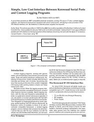
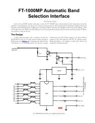
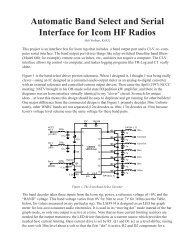
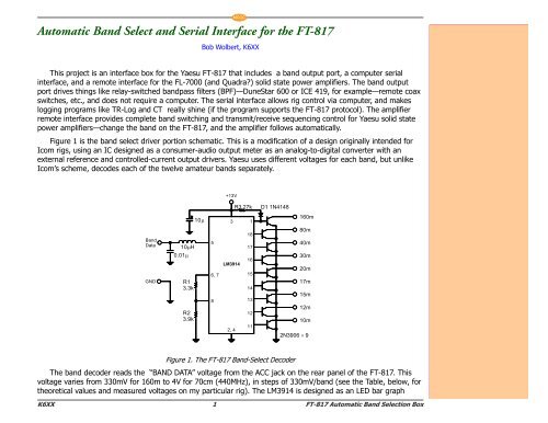
Figure 1 is the band select driver portion schematic. This is a modification of a design originally intended for<br />
I<strong>com</strong> rigs, using an IC designed as a consumer-audio output meter as an analog-to-digital converter with an<br />
external reference and controlled-current output drivers. Yaesu uses different voltages for each band, but unlike<br />
I<strong>com</strong>’s scheme, decodes each of the twelve amateur bands separately.<br />
<br />
<br />
<br />
<br />
<br />
<br />
<br />
<br />
<br />
<br />
<br />
<br />
<br />
<br />
<br />
<br />
<br />
<br />
<br />
<br />
<br />
<br />
<br />
<br />
<br />
<br />
<br />
<br />
<br />
<br />
<br />
<br />
<br />
<br />
<br />
<br />
<br />
<br />
Figure 1. The <strong>FT</strong>-<strong>817</strong> <strong>Band</strong>-Select Decoder<br />
The band decoder reads the “BAND DATA” voltage from the ACC jack on the rear panel of the <strong>FT</strong>-<strong>817</strong>. This<br />
voltage varies from 330mV for 160m to 4V for 70cm (440MHz), in steps of 330mV/band (see the Table, below, for<br />
theoretical values and measured voltages on my particular rig). The LM3914 is designed as an LED bar graph<br />
K6XX 1 <strong>FT</strong>-<strong>817</strong> <strong>Automatic</strong> <strong>Band</strong> <strong>Selection</strong> <strong>Box</strong>
K6XX 2 <strong>FT</strong>-<strong>817</strong> <strong>Automatic</strong> <strong>Band</strong> <strong>Selection</strong> <strong>Box</strong><br />
NCCC<br />
<br />
<br />
<br />
<br />
<br />
<br />
<br />
<br />
<br />
<br />
<br />
<br />
<br />
<br />
<br />
<br />
<br />
<br />
<br />
<br />
<br />
<br />
<br />
<br />
<br />
<br />
<br />
<br />
<br />
<br />
<br />
<br />
<br />
<br />
<br />
<br />
<br />
<br />
<br />
<br />
<br />
<br />
<br />
<br />
<br />
<br />
<br />
<br />
<br />
<br />
<br />
<br />
<br />
<br />
<br />
<br />
<br />
<br />
<br />
<br />
<br />
<br />
<br />
<br />
<br />
<br />
<br />
<br />
<br />
<br />
<br />
<br />
<br />
<br />
<br />
<br />
<br />
<br />
<br />
<br />
<br />
<br />
<br />
<br />
<br />
<br />
<br />
<br />
<br />
<br />
<br />
<br />
<br />
<br />
<br />
<br />
<br />
<br />
<br />
<br />
<br />
<br />
<br />
<br />
<br />
<br />
<br />
<br />
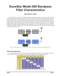
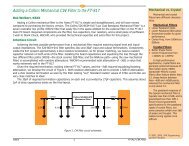
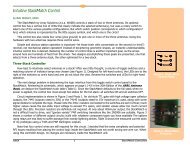
Figure 2. <strong>FT</strong>-<strong>817</strong> Interface Schematic
meter for low-cost consumer audio electronics. It is used in its “moving dot” mode instead of the bar graph mode,<br />
so only one output is active at a time. Note that no base current limiting resistors are needed for the output<br />
transistors: the LED driver functions as a current source which provides the needed base current limiting. Base<br />
current drive is set by R1, and is 3.3kW here. R2 works with R1 to scale the LM3914 to the 3V maximum value of<br />
BAND DATA in the HF bands. R3 and D1 <strong>com</strong>pensate for a LM3914 “funny”—the first output draws several hundred<br />
microamperes of current even when the other outputs are selected., and this is enough to turn on the 160m<br />
driver slightly. R3 <strong>com</strong>pensates by providing another path for this current. Its value might need tweaking for<br />
individual LM3914s and different supply voltages. D1 prevents reverse current flow from the relay into the rig,<br />
although is not really necessary—since the “+13.8V” pin on the ACC jack is always ON (even when the rig is<br />
powered down), I strongly re<strong>com</strong>mend using a separate supply for the BPF relay drivers interface.<br />
The <strong>com</strong>puter serial interface is adapted from a design by “Russia Tomsk” that was modified by VE3CVG.<br />
Using voltage from the rig is acceptable here, since the normal current drain is zero. A normal 9-pin or 25-pin DB<br />
connector attaches to the <strong>com</strong>puter’s serial port.<br />
Like most serial interfaces, getting the hardware built and connected is only part of the task; convincing the<br />
software in the <strong>com</strong>puter and the radio to speak is usually much more frustrating, especially if you have not done<br />
it before with a given program or rig. Yaesu further muddies the waters by introducing different <strong>com</strong>mand sets<br />
with each radio model, so ensure your software understands <strong>FT</strong>-<strong>817</strong>-speak. You are on your own here!<br />
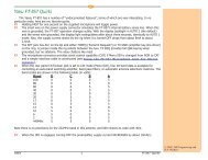
The FL-7000 interface uses a 74HC147 priority encoder. It looks at the active low band data outputs and<br />
outputs four bits that represent the active band. The amplifier uses this code to select the proper internal bandpass<br />
filters. Keying is performed by the TX GND line, which is a direct connection between the open collector<br />
driver inside the <strong>817</strong> and the amplifier T/R line. TX INH is a timing line that limits drive power until the amplifier<br />
has switched into the transmit mode. Voltage must be applied to the amplifier’s “+13.5” line or else the amplifier<br />
will not key. Nine 1N4148 diodes protect the 5V logic IC from the 12V coil voltage from the BPF relay bank.<br />
Figure 2 shows the <strong>com</strong>plete interface schematic. I tried to minimize the number of different resistor and<br />
capacitor values; only R1, R2, and R3 are semi-critical; the others may vary quite a bit without affecting circuit<br />
operation. The <strong>com</strong>ponent cost of the full interface is relatively low: well under $20 at Digi-Key mail order prices.<br />
You can probably build this box for under $10 by visiting flea markets and the local electronics “junk stores”.<br />
73 & GL de Bob, K6XX<br />
• k6xx@arrl.net<br />
• Return to the K6XX Web Site<br />
NCCC<br />
Copyr<br />
yright © 2001, Bob Wolber<br />
olbert,<br />
K6XX<br />
Version 1.0 02MR01<br />
Appendix: Measured<br />
BAND Pin Voltages<br />
<strong>Band</strong> Specified Measured<br />
160m 0.33 0.336<br />
80m 0.66 0.692<br />
40m 1.0 1.03<br />
30m 1.3 1.31<br />
20m 1.6 1.65<br />
17m 2.0 2.00<br />
15m 2.3 2.34<br />
12m 2.7 2.61<br />
10m 3.0 2.95<br />
6m† 3.3 3.31<br />
2m† 3.7 3.64<br />
70cm† 4.0 3.93<br />
† <strong>Band</strong> not supported by this<br />
interface.<br />
Design and measured BAND<br />
DATA voltage on my particular<br />
<strong>FT</strong>-<strong>817</strong>.<br />
K6XX 3 <strong>FT</strong>-<strong>817</strong> <strong>Automatic</strong> <strong>Band</strong> <strong>Selection</strong> <strong>Box</strong>