printable Band Select/CI-V (PDF format) - K6xx.com
printable Band Select/CI-V (PDF format) - K6xx.com
printable Band Select/CI-V (PDF format) - K6xx.com

You also want an ePaper? Increase the reach of your titles
YUMPU automatically turns print PDFs into web optimized ePapers that Google loves.
Automatic <strong>Band</strong> <strong>Select</strong> and Serial<br />
Interface for I<strong>com</strong> HF Radios<br />
Bob Wolbert, K6XX<br />
This project is an interface box for I<strong>com</strong> rigs that includes a band output port and a <strong>CI</strong>-V–to–<strong>com</strong>puter<br />
serial interface. The band output port drives things like relay-switched DuneStar band filters<br />
(Model 600, for example), remote coax switches, etc., and does not require a <strong>com</strong>puter. The <strong>CI</strong>-V<br />
interface allows rig control via <strong>com</strong>puter, and makes logging programs like TR-Log and CT really<br />
shine.<br />
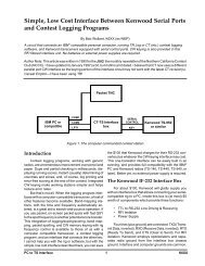
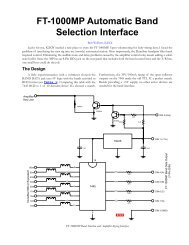
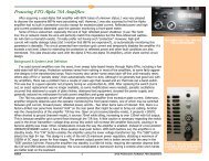
Figure 1 is the band select driver portion schematic. When I designed it, I thought I was being really<br />
clever—using an IC designed as a consumer-audio output meter as an analog-to-digital converter<br />
with an external reference and controlled-current output drivers. Then came the April (1997) NCCC<br />
meeting: N6TV brought in his OH-made solid state DXpedition kW amplifier, and there in the<br />
diagrams was an I<strong>com</strong> interface virtually identical to my “clever” circuit. So much for unique<br />
ideas…at least this means this design should be easy to duplicate and get running for other builders!<br />
One major difference from the <strong>com</strong>mercial design is that Figure 1 properly decodes 30m. Unfortunately,<br />
other WARC bands are not separated (12m decodes as 10m; 17m decodes as 15m) because<br />
I<strong>com</strong>’s voltage level scheme uses the same voltage for these band pairs.<br />
27k* 1N4148<br />
ACC2<br />
Pin 7<br />
(+13.8V)<br />
Pin 1<br />
(+8V)<br />
220µ<br />
0.1µ<br />
220µ<br />
0.1µ<br />
4.7µ<br />
10k<br />
3<br />
6<br />
R2<br />
D2<br />
LM3914<br />
LED Driver<br />
1<br />
17<br />
15<br />
14<br />
Q2<br />
Q3<br />
Q4<br />
Q5<br />
0.47µH ( 7)<br />
30m<br />
0.1µ<br />
10m/12m<br />
0.1µ<br />
15m/17m<br />
0.1µ<br />
20m<br />
0.1µ<br />
Pin 4<br />
(BAND)<br />
220µ<br />
1N4148<br />
0.1µ D1<br />
3.3k<br />
Q1<br />
2N3906<br />
R1<br />
5<br />
7<br />
9<br />
N.C.<br />
13<br />
12<br />
11<br />
2,4,8<br />
Q6<br />
Q7<br />
Q8<br />
TIP150 ( 7)<br />
0.1µ<br />
0.1µ<br />
0.1µ<br />
40m<br />
80m<br />
160m<br />
Figure 1. The I<strong>com</strong> <strong>Band</strong>-<strong>Select</strong> Decoder<br />
The band decoder takes three inputs from the I<strong>com</strong> rig: power, a reference voltage of +8V, and the<br />
“BAND” voltage. This band voltage varies from 0V for 30m to over 7V for 160m (see the Table,<br />
below, for values measured on my particular rig). The LM3914 is designed as an LED bar graph<br />
meter for low-cost consumer audio electronics. It is used in its “moving dot” mode instead of the bar<br />
graph mode, so only one output is active at a time. Note that no base current limiting resistors are<br />
needed for the output transistors: the LED driver functions as a current source which provides the<br />
needed base current limiting. Base current drive is set by R1. Q1 and D1 act as a level-shifter, raising<br />
the zero-volt 30m level about a volt so that the first “dot” is active. R2 and D2 <strong>com</strong>pensate for a
LM3914 “funny”—the first output draws several hundred microamperes of current even when the<br />
other outputs are selected. This is enough to turn on Q2 slightly. R2 <strong>com</strong>pensates by providing<br />
another path for this current. Its value might need tweaking for individual LM3914s and different<br />
supply voltages. D2 prevents reverse current flow from the relay into the rig.<br />
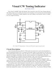
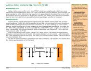
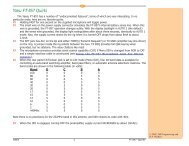
The <strong>CI</strong>-V–to–<strong>com</strong>puter serial interface schematic appears as Figure 2. It uses a low-cost dual opamp<br />
and a zener diode for level conversion. A 555 timer is used as an oscillator and charge pump to<br />
produce the negative voltage. Since power is already available from the band decoder port, no<br />
attempt at self-powering through the RS-232 port is made. You could probably derive the negative<br />
supply from the serial port and eliminate the 555 charge pump. I<strong>com</strong> uses a unique system with<br />
bidirectional control (with multiradio<br />
capability) through a single<br />
wire (plus ground). A standard<br />
miniature (1/8") mono phone plug<br />
connects to the radio’s “<strong>CI</strong>-V”<br />
port. A normal 9-pin or 25-pin DB<br />
connector attaches to the<br />
<strong>com</strong>puter’s serial port.<br />
Like most of these interfaces,<br />
getting the hardware built and<br />
connected is only part of the task;<br />
convincing the software in the<br />
<strong>com</strong>puter and the radio to speak is<br />
usually much more frustrating,<br />
especially if you have not done it<br />
before with a given program or<br />
rig. You are on your own here!<br />
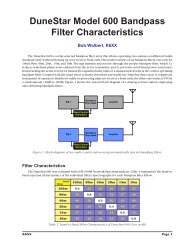
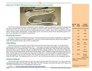
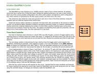
Figure 3 shows the <strong>com</strong>plete interface schematic. I tried to minimize the number of different resistor<br />
and capacitor values; only R1 and R2 are critical; the others may vary quite a bit without affecting<br />
circuit operation. The <strong>com</strong>ponent cost of the full interface is relatively low: well under $20 at Digi-<br />
Key mail order prices. You can probably build this box for under $10 by visiting the flea market and<br />
the local “junk stores”.<br />
73 & GL de Bob, K6XX<br />
<strong>CI</strong>-V<br />
Port<br />
+9 to 12V<br />
4.7µ<br />
1N4148<br />
( 2)<br />
1<br />
2<br />
3<br />
4<br />
100 27k<br />
100<br />
27k<br />
555<br />
Timer<br />
4.7µ<br />
8<br />
7<br />
6<br />
5<br />
4.7V<br />
0.1µ<br />
6<br />
5<br />
1N4148<br />
NC<br />
3.3k 3.3k<br />
1<br />
27k<br />
4<br />
4558<br />
Dual Op Amp<br />
8<br />
7<br />
2<br />
3<br />
0.1µ<br />
27k<br />
100<br />
Figure 2. <strong>CI</strong>-V to Serial Converter<br />
RS-232<br />
Connector<br />
DB-25<br />
GND (7)<br />
TXD (2)<br />
RXD (3)<br />
Copyright © 1997, Bob Wolbert, K6XX
27k* 1N4148<br />
ACC2<br />
Pin 7<br />
(+13.8V)<br />
Pin 1<br />
(+8V)<br />
220µ<br />
0.1µ<br />
220µ<br />
0.1µ<br />
4.7µ<br />
10k<br />
3<br />
6<br />
R2<br />
D2<br />
LM3914<br />
LED Driver<br />
1<br />
17<br />
15<br />
14<br />
Q2<br />
Q3<br />
Q4<br />
Q5<br />
0.47µH ( 7)<br />
30m<br />
0.1µ<br />
0.1µ<br />
0.1µ<br />
0.1µ<br />
10m/12m<br />
15m/17m<br />
20m<br />
Pin 4<br />
(BAND)<br />
220µ<br />
0.1µ<br />
1N4148<br />
D1<br />
3.3k<br />
Q1<br />
2N3906<br />
R1<br />
5<br />
7<br />
9<br />
N.C.<br />
13<br />
12<br />
11<br />
2,4,8<br />
Q6<br />
Q7<br />
Q8<br />
TIP150 ( 7)<br />
0.1µ<br />
0.1µ<br />
0.1µ<br />
40m<br />
80m<br />
160m<br />
1<br />
8<br />
3.3k 3.3k<br />
2<br />
3<br />
555<br />
Timer<br />
7<br />
6<br />
4<br />
5<br />
NC<br />
0.1µ<br />
RS-232<br />
Connector<br />
DB-25<br />
4.7µ<br />
GND (7)<br />
1N4148<br />
( 2)<br />
4.7µ<br />
27k<br />
<strong>CI</strong>-V<br />
Port<br />
100 27k<br />
4.7V<br />
0.1µ<br />
100 6<br />
27k 5<br />
1<br />
4<br />
4558<br />
Dual Op Amp<br />
8<br />
7<br />
2<br />
3<br />
27k<br />
100<br />
TXD (2)<br />
RXD (3)<br />
1N4148<br />
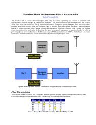
Appendix: Measured BAND Pin Voltages<br />
Figure 3. Full Interface Schematic<br />
<strong>Band</strong><br />
BAND Pin<br />
Voltag<br />
oltage<br />
10<br />
3. 5<br />
15<br />
4. 3<br />
20<br />
5<br />
30<br />
0<br />
40<br />
6<br />
80<br />
6. 6<br />
160<br />
7. 5<br />
Measured BAND output voltage on my particular IC756.