Intuitive StackMatch Control - K6xx.com
Intuitive StackMatch Control - K6xx.com
Intuitive StackMatch Control - K6xx.com

You also want an ePaper? Increase the reach of your titles
YUMPU automatically turns print PDFs into web optimized ePapers that Google loves.
<strong>Intuitive</strong> <strong>StackMatch</strong> <strong>Control</strong><br />
NCCC<br />
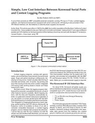
by Bob Wolbert, K6XX<br />
The <strong>StackMatch</strong> by Array Solutions (a.k.a. WX0B) controls a stack of two or three antennas. Its optional<br />
control box has a vertical line of LEDs that clearly indicate the selected antenna(s), but uses a rotary switch to<br />
select one of the various possible configurations. But which switch position corresponds to which configuration<br />
And, which antenna is represented by the little square symbol, and which one is the circle<br />
This control box also needs four wires (plus ground) to pick one or more of the three antennas. Using this<br />
hardware with two antennas requires three control wires.<br />
Simple and obvious station operation is important—let those brain cells concentrate on the second (or third)<br />
receiver, not mechanical station operation! Instead of deciphering geometric shapes, an instantly understandable,<br />
intuitive control box is desired. Reducing the number of control lines is another important goal, as the arrays<br />
around here are hundreds of feet from the shack. Two designs ac<strong>com</strong>plishing these goals are presented, one that<br />
selects from a three-antenna stack, the other optimized for a two-stack.<br />
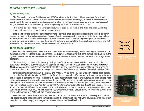
Three-Stack <strong>Control</strong>ler<br />
How best to intuitively select antennas in a stack After very little thought, a column of toggle switches and a<br />
matching column of indicator lamps was chosen (see Figure 1). Designed for left-hand control, the LEDs are to the<br />
right of the switches so one’s hand and arm do not block the view. Reverse the switches and LEDs for right-hand<br />
operation.<br />
The next design problem is determining the logic interface from this toggle switch control panel to the<br />
<strong>StackMatch</strong>. Reviewing its schematic, which appears on page 11-43 in the 20th Edition of the ARRL Antenna<br />
Book, we deduce the <strong>StackMatch</strong> truth table (Table I). Since the <strong>StackMatch</strong> defaults to the full stack when no<br />
power is applied, the control box must accept two states for the full stack: all switches ON and all switches OFF.<br />
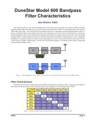
Circuit implementation is shown in Figure 2 and Photo 1. An old-style TTL gate with high voltage open collector<br />
outputs, the 7445 (outputs rated to 30V) or the 74145 (outputs rated to 15V maximum) is used, along with some<br />
signal diodes to <strong>com</strong>plete the logic. Please note the 330W resistors connected to the switches are semi-critical; much<br />
higher values cause the low-state input voltage to exceed TTL specs, and smaller values allow too much current<br />
through the LEDs. Precision resistors are definitely not required. At only about 40mA per output, the <strong>StackMatch</strong> is<br />
not a difficult load to drive, and “garden variety” PNP switching transistors like the 2N3906 are suitable. Figure 3<br />
shows a number of different output circuits: build with whatever <strong>com</strong>ponent types you have available The options<br />
using relays are less likely to suffer damage from nearby lightning strikes. Table II shows the measured current drain<br />
of my prototype using a 7445 and PNP Darlington outputs.<br />
Note that four control wires are still required for this circuit. I decided that the extra <strong>com</strong>plexity and potential<br />
RFI issues resulting from placing the control logic inside the <strong>StackMatch</strong> was not worth saving one wire run. When<br />
using this controller design, no changes are necessary inside the <strong>StackMatch</strong> unit.<br />
<br />
<br />
<br />
Figure 1. Three-Stack<br />
<strong>Control</strong> Panel.<br />
Photo 1. Three-Stack<br />
Prototype.<br />
K6XX 1 <strong>StackMatch</strong> <strong>Control</strong>lers
NCCC<br />
Table I. <strong>StackMatch</strong> <strong>Control</strong>ler Logic for a Three-Stack<br />
<br />
Toggle Switch<br />
(and Antenna)<br />
<strong>Control</strong> Line<br />
IN 3 2 1<br />
Top + Mid + Bottom 0 0 0 0<br />
Top + Mid 0 0 0 1<br />
Top + Bottom 0 0 1 0<br />
Mid + Bottom 0 1 0 0<br />
Bottom 1 0 0 1<br />
Mid 1 0 1 0<br />
Top 1 1 0 0<br />
<br />
<br />
<br />
<br />
<br />
<br />
<br />
<br />
(A) PNP Darlington with<br />
internal diode<br />
<br />
<br />
<br />
<br />
<br />
(B) P-Channel Power MOSFET<br />
<br />
<br />
<br />
<br />
<br />
<br />
<br />
<br />
<br />
<br />
<br />
<br />
<br />
<br />
<br />
<br />
<br />
<br />
<br />
<br />
<br />
<br />
<br />
<br />
<br />
<br />
<br />
<br />
<br />
<br />
<br />
<br />
<br />
<br />
<br />
<br />
<br />
<br />
<br />
<br />
<br />
<br />
<br />
<br />
<br />
<br />
<br />
<br />
<br />
<br />
<br />
<br />
(C) SPST Relay with 12V coil<br />
<br />
<br />
<br />
<br />
<br />
<br />
(D) SPST Relay with a 5V Coil.<br />
Figure 3. Three-Stack<br />
Output Options<br />
Figure 2. Three-Stack <strong>Control</strong>ler using PNP output Transistors.<br />
K6XX 2 <strong>StackMatch</strong> <strong>Control</strong>lers
NCCC<br />
<br />
<br />
Table II. Current Drain<br />
(Figure 2), V IN<br />
= 13.6V<br />
<br />
<br />
<br />
<br />
<br />
Configuration<br />
All Switches OFF<br />
All Switches ON<br />
One or Two<br />
Antennas Selected<br />
(worst case)<br />
Current<br />
38mA<br />
60mA<br />
144mA<br />
<br />
<br />
<br />
<br />
<br />
<br />
<br />
<br />
<br />
<br />
<br />
<br />
<br />
Table III. Single-Wire<br />
<strong>Control</strong>ler logic.<br />
<br />
<br />
<br />
<br />
<br />
Switch Voltage Antenna<br />
(none) 0 both<br />
Upper +12 Top<br />
Lower –12 Bottom<br />
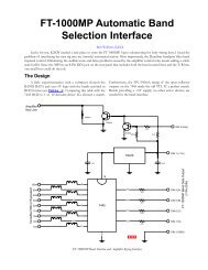
Figure 4. Two-Stack <strong>Control</strong>ler and Additional Diodes Needed Inside the <strong>StackMatch</strong>.<br />
Two Antenna Stacks<br />
If a stack has only two antennas, we can design a control box that reduces the wiring requirement from three<br />
to only one wire. Using both positive and negative drive voltages this may be ac<strong>com</strong>plished as described in Table<br />
III.<br />
K6XX 3 <strong>StackMatch</strong> <strong>Control</strong>lers
Figure 4 shows the two-stack design. No ICs or transistors are required. Since the control box needs –12V,<br />
and no other use for this voltage presently exists at K6XX, a dedicated power supply was designed using an AC<br />
output “wall wart” (a small 12.6V transformer is also suitable). A semi-tricky aspect of this circuit is the LED<br />
display, which must have both LEDs ON when the relays are OFF, and is ac<strong>com</strong>plished by shorting out the opposite<br />
LEDs by the control switches. In other words, the TOP control switch shorts out the BOTTOM LED, and viceversa.<br />
The LED current passes though the <strong>StackMatch</strong> relay coils, so they will not illuminate unless the<br />
<strong>StackMatch</strong> is connected. This small current (about 1mA) is insufficient to either trigger or hold the relays, so their<br />
operation is unaffected. However, only 1mA is less than the 10mA normally used for LEDs, so if you find their<br />
luminosity too dim, consider changing to high efficiency LEDs. Do not reduce the current-limiting resistor values or<br />
else the <strong>StackMatch</strong> relays might not release after they<br />
have been activated. On my prototype, 50mF of filter<br />
capacitance was required on both the positive and<br />
negative supplies to eliminate relay chattering due to the<br />
half-wave rectified 60Hz. I re<strong>com</strong>mend using at least<br />
100mF of filtering on both supplies to provide some<br />
margin, unless a negative DC supply is available.<br />
Figure 5 shows two possible control panels. Some<br />
may find the two-switch version is more intuitive, but the<br />
single switch version allows faster, single-finger stack<br />
selection and optimization—with it, UP is the top antenna<br />
only, CENTER is the full stack, and DOWN is the lower<br />
antenna only.<br />
Photo 2. Diodes necessary inside the <strong>StackMatch</strong> for the<br />
single-wire two-stack controller<br />
NCCC<br />
Two diodes are added to the <strong>StackMatch</strong> when used<br />
with the single-wire controller. This is a screwdriver-only<br />
operation—no traces must be cut and no soldering is<br />
involved. The diodes are easily installed on the internal<br />
control wire terminal strip, as shown in Photograph 2.<br />
<br />
<br />
(A) Two SPST Switches<br />
<br />
<br />
<br />
(B) SPDT, Center OFF Switch<br />
allows faster stack checking..<br />
Figure 5. Two-Stack<br />
<strong>Control</strong>ler Panel<br />
Summary<br />
RF-wise, the <strong>StackMatch</strong> is a well-designed system for selecting among antennas in a stack. The control box<br />
from Array Solutions, however, is not as well thought out. The controllers presented here allow more intuitive and<br />
simpler means of selecting your stack.<br />
K6XX 4 <strong>StackMatch</strong> <strong>Control</strong>lers<br />
ver 1.01 2Jy04