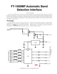
DuneStar Model 504 Bandpass Filter Characteristics - K6xx.com
DuneStar Model 504 Bandpass Filter Characteristics - K6xx.com
DuneStar Model 504 Bandpass Filter Characteristics - K6xx.com

Create successful ePaper yourself
Turn your PDF publications into a flip-book with our unique Google optimized e-Paper software.
<strong>DuneStar</strong> <strong>Model</strong> <strong>504</strong> <strong>Bandpass</strong> <strong>Filter</strong> <strong>Characteristics</strong><br />
By Bob Wolbert, K6XX<br />
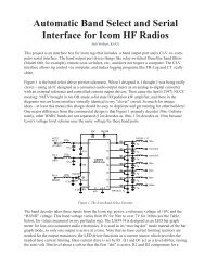
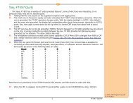
The <strong>DuneStar</strong> <strong>504</strong> is a relay-selected bandpass filter array that allows operating two stations on different bands<br />
simultaneously—without blowing up your receiver front-ends. This model consists of five bandpass filters, one each for<br />
160m, 80m, 40m, 20m, and 15m. The rig transmits and receives through the proper bandpass filter, which 1), reduces<br />
wideband phase noise radiated from the transmitter; and 2), prevents out-of-band power (and noise) from reaching the<br />
receiver. A band select signal from a manual switch or the radio selects the correct operating band. Coupled with the band<br />
select schemes described previously, the <strong>DuneStar</strong> filter array is <strong>com</strong>pletely transparent in operation. Besides its utility in<br />
protecting adjacent receiver’s front ends, the filters also reduces TVI by a small amount (15dB to 20dB). Figure 1 shows the<br />
system block diagram of a dual-rig contest station employing autoswitching bandpass filters.<br />
Rig 1<br />
<strong>Bandpass</strong><br />
<strong>Filter</strong> Bank<br />
Amplifier<br />
Band Control<br />
Information<br />
Rig 2<br />
<strong>Bandpass</strong><br />
<strong>Filter</strong> Bank<br />
Amplifier<br />
Band Control<br />
Information<br />
Figure 1. Block diagram of two radio contest station using automatically selected bandpass filters.<br />
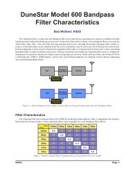
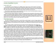
<strong>Filter</strong> <strong>Characteristics</strong><br />
The <strong>DuneStar</strong> <strong>504</strong> was evaluated with a HP 4396B Network/Spectrum analyzer. Table 1 summarizes the band-to-band<br />
rejection characteristics of the individual filters. Oscillographs for each bandpass filter follow.<br />
<strong>Filter</strong> 160 80 40 20 15<br />
160 0.9 34 47 41 60<br />
80 45 0.8 34 42 43<br />
40 52 44 0.9 40 42<br />
20 54 48 54 0.3 30<br />
15 55 51 47 48 1<br />
Table 1. Band-to Band <strong>Filter</strong> <strong>Characteristics</strong> of <strong>DuneStar</strong> <strong>504</strong> (Loss in dB)
<strong>Filter</strong> Oscillographs<br />
160m <strong>Filter</strong> from 1MHz to 30MHz<br />
80m <strong>Filter</strong> from 1MHz to 30MHz<br />
160m <strong>Filter</strong>—Band-to-Band <strong>Characteristics</strong><br />
80m <strong>Filter</strong>—Band-to-band <strong>Characteristics</strong><br />
160m <strong>Filter</strong>—Broadband <strong>Characteristics</strong> to 150MHz<br />
80m <strong>Filter</strong>— Broadband <strong>Characteristics</strong> to 150MHz
40m <strong>Filter</strong> from 1MHz to 30MHz<br />
20m <strong>Filter</strong> from 1MHz to 30MHz<br />
40m <strong>Filter</strong>—Band-to-band <strong>Characteristics</strong><br />
20m <strong>Filter</strong>—Band-to-band <strong>Characteristics</strong><br />
40m <strong>Filter</strong>—High Frequency Rejection to 150MHz<br />
20m <strong>Filter</strong>—High Frequency Rejection to 150MHz
15m <strong>Filter</strong> from 1MHz to 30MHz<br />
15m <strong>Filter</strong>—Band-to-band <strong>Characteristics</strong><br />
15m <strong>Filter</strong> High Frequency Rejection to 150MHz