FT-857 Serial Cable via Microphone Jack - K6xx.com
FT-857 Serial Cable via Microphone Jack - K6xx.com
FT-857 Serial Cable via Microphone Jack - K6xx.com

Create successful ePaper yourself
Turn your PDF publications into a flip-book with our unique Google optimized e-Paper software.
Using the <strong>FT</strong>-<strong>857</strong> <strong>Microphone</strong> <strong>Jack</strong> for <strong>Serial</strong> Control (CAT)<br />
NCCC<br />
The <strong>FT</strong>-<strong>857</strong> manual hints that the microphone jack is capable of <strong>com</strong>municating with a personal <strong>com</strong>puter (see<br />
the section on Menu 059, “MIC SEL”; this is on page 107 of the <strong>FT</strong>-<strong>857</strong>D manual). This allows using the “CAT/<br />
Linear” jack on the rear panel for either the external antenna tuner or (what I need it for) to access the 4-bit band<br />
data in “Linear” mode. Unfortunately, no other data is given—not even the pinout of the microphone jack(!!). For<br />
any of you interested, the “mystery” is solved here.<br />
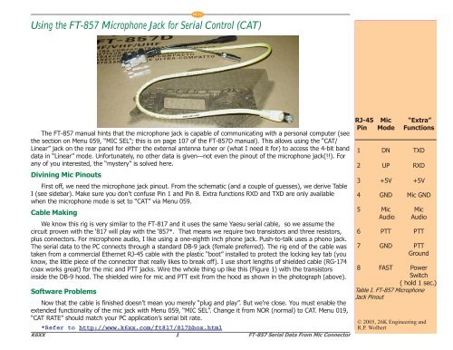
Divining Mic Pinouts<br />
First off, we need the microphone jack pinout. From the schematic (and a couple of guesses), we derive Table<br />
I (see sidebar). Make sure you don’t confuse Pin 1 and Pin 8. Extra functions RXD and TXD are only available<br />
when the microphone mode is set to “CAT” <strong>via</strong> Menu 059.<br />
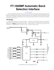
<strong>Cable</strong> Making<br />
We know this rig is very similar to the <strong>FT</strong>-817 and it uses the same Yaesu serial cable, so we assume the<br />
circuit proven with the ‘817 will play with the ‘<strong>857</strong>*. That means we require two transistors and three resistors,<br />
plus connectors. For microphone audio, I like using a one-eighth inch phone jack. Push-to-talk uses a phono jack.<br />
The serial data to the PC connects through a standard DB-9 jack (female preferred). The rig end of the cable was<br />
taken from a <strong>com</strong>mercial Ethernet RJ-45 cable with the plastic “boot” installed to protect the locking key tab (you<br />
know, the little piece of the connector that really likes to break off). I use short lengths of shielded cable (RG-174<br />
coax works great) for the mic and PTT jacks. Wire the whole thing up like this (Figure 1) with the transistors<br />
inside the DB-9 hood. The shielded wire for mic and PTT exit from the hood as shown in the photograph (above).<br />
Software Problems<br />
Now that the cable is finished doesn’t mean you merely “plug and play”. But we’re close. You must enable the<br />
extended functionality of the mic jack with Menu 059, “MIC SEL”. Change it from NOR (normal) to CAT. Menu 019,<br />
“CAT RATE” should match your PC application’s serial bit rate.<br />
*Refer to http://www.k6xx.<strong>com</strong>/ft817/817bbox.html<br />
K6XX 1 <strong>FT</strong>-<strong>857</strong> <strong>Serial</strong> Data From Mic Connector<br />
RJ-45 Mic “Extra”<br />
Pin Mode Functions<br />
1 DN TXD<br />
2 UP RXD<br />
3 +5V +5V<br />
4 GND Mic GND<br />
5 Mic Mic<br />
Audio Audio<br />
6 PTT PTT<br />
7 GND PTT<br />
Ground<br />
8 FAST Power<br />
Switch<br />
( hold 1 sec.)<br />
Table I. <strong>FT</strong>-<strong>857</strong> <strong>Microphone</strong><br />
<strong>Jack</strong> Pinout<br />
© 2005, 26K Engineering and<br />
R.P. Wolbert
NCCC<br />
<br />
<br />
<br />
<br />
Ω<br />
<br />
Ω<br />
<br />
Ω<br />
<br />
<br />
<br />
<br />
<br />
<br />
<br />
<br />
<br />
<br />
<br />
<br />
<br />
<br />
Figure 1. <strong>FT</strong>-<strong>857</strong> <strong>Serial</strong> Data from the <strong>Microphone</strong> <strong>Jack</strong> circuit.<br />
Now you are free to change the rear panel CAT/Linear jack control, Menu 020, “CAT/LIN/TUN”, to your choice<br />
of Tuner or Linear, and still have serial <strong>com</strong>munications. Incidentally, my mic jack cable worked fine even though I<br />
left Menu 020 in CAT. The rig saw no conflict even though its serial data sprayed out two different ports.<br />
Operation and an Alternative<br />
With this cable, I now have my <strong>FT</strong>-<strong>857</strong> talking to a logging program through the mic jack and <strong>com</strong>municating<br />
its active band to my automatic antenna/bandpass filter/amplifier selection interfaces through its CAT/Linear jack<br />
in “Linear” mode. When the need arises, I can connect a headset or boom microphone to the mic connector and a<br />
foot switch to the PTT input and use this little mobile rig as if it was a much larger fixed station transceiver.<br />
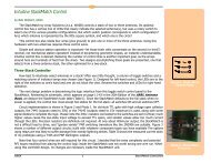
There was another option considered: use the interface circuit I designed for the <strong>FT</strong>-817 and decode the BAND<br />
voltage (available on the CAT/Linear jack in CAT mode) into its 4-bit values. However, this solution requires at<br />
least two ICs and four transistors and then only decodes 160m through 10m. Reading the VHF/UHF bands would<br />
require a doubling of circuit <strong>com</strong>plexity. Since a boom-mic headset input was desired anyway, this microphone/<br />
serial interface cable was the simplest and best solution.<br />
K6XX 2 <strong>FT</strong>-<strong>857</strong> <strong>Serial</strong> Data From Mic Connector<br />
Rev 1.02. 13 June 2005<br />
© 2005, 26K Engineering and<br />
R.P. Wolbert