FT-817 CW Filter - K6xx.com
FT-817 CW Filter - K6xx.com
FT-817 CW Filter - K6xx.com

Create successful ePaper yourself
Turn your PDF publications into a flip-book with our unique Google optimized e-Paper software.
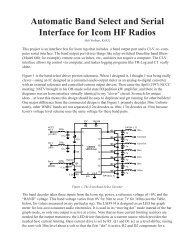
Adding a Collins Mechanical <strong>CW</strong> <strong>Filter</strong> to the <strong>FT</strong>-<strong>817</strong>Bob Wolbert, K6XXAdding a Collins mechanical filter to the Yaesu <strong>FT</strong>-<strong>817</strong> is simple and straightforward, and will save money<strong>com</strong>pared to purchasing the factory version. The Collins 526-8634-010 “Low Cost Bandpass Mechanical <strong>Filter</strong>” is aseven resonator low profile 455kHz filter that easily fits in the space allotted for the external filter on the <strong>FT</strong>-<strong>817</strong>main PC board. Required <strong>com</strong>ponents are the filter, two capacitors, four resistors, and a small piece of perfboard.I wish to thank Chuck, W6CAM, who provided the technical expertise and extra filter for this project.Interface CircuitAchieving the best possible performance from a mechanical filter requires matching signal level and input/output impedances. The 526-8634-010 filter specifies 2kΩ and 30pF input and output terminations. Componentsinside the <strong>817</strong> present approximately 2.2kΩ resistive termination, so for proper matching, we need a resistor/capacitor network on both ends of the filter. Isolating the board capacitance and equalizing the loss through thetwo different filter paths (WIDE—the stock ceramic SSB filter, and the NARrow path—using the new mechanicalfilter) is ac<strong>com</strong>plished with resistive attenuators. W6CAM re<strong>com</strong>mended total attenuation of –3dB, a value thatworks extremely well in the <strong>FT</strong>-<strong>817</strong>.Given the required termination, existing internal <strong>FT</strong>-<strong>817</strong> values, and the –3dB required equalizing/isolatingattenuation, we develop the circuit of Figure 1. Both resistive attenuators are set to provide 1.5dB of attenuationand a 2kΩ resistive termination as seen by the filter looking “out”. Standard resistor values of 470Ω and 8.2kΩ arevery close matches to ideal.The 30pF of required termination capacitance on each end is provided by 27pF capacitors. This assumes about3pF of stray capacitance exists on the final layout.NCCCMechanical vs. CrystalMechanical and crystalfilters have different characteristics.Mechanical <strong>Filter</strong>s• Lower Passband ripple• Lower Passband Attenuation• Somewhat smaller for givenperformance• Center Freq. from 100kHz to600kHzCrystal <strong>Filter</strong>s• Better Shape Factor• Center Frequencies from20MHzIn high performanceapplications, crystal filters aregenerally preferred because oftheir better skirts; 500Hzbandwidth 455kHz crystalfilters often feature better than2:1 shape factors betweentheir –6dB and –60dB points,whereas the mechanical filteris only about 3:1. The passband response ofthe typical mechanical filter istypically less than 0.5dB, and isguaranteed less than 3dB. Ihaven’t found guaranteedspecifications for the passbandripple of crystal filters, butsome samples exhibit over 5dBof peaks and troughs. Thismakes tuning signals moredifficult.Figure 1. <strong>CW</strong> filter circuit schematicK6XX 1 <strong>FT</strong>-<strong>817</strong> <strong>CW</strong> <strong>Filter</strong>© 2001, 2005, 26K Engineeringand R.P. Wolbert
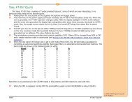
NCCCPC Board Layout?No PC board layout is (yet) available for this project. If you have the wherewithal, please lay out the board forus! The <strong>FT</strong>-857 and <strong>FT</strong>-897 use the same filter boards, but implement a coding scheme where the PC board itself<strong>com</strong>municates it presence and its filter bandwidth to the rigs microprocessor by grounding certain pins. The rigresponds by adjusting its BFO injection frequency. You might as well add this coding to your filter so it may beused in the other rigs, since filters without this coding may require IF Shift to center the passband—and regardlessof what the manual state, IF Shift is NOT remembered between operating sessions.The code for each of the three Yaesu optional filters is shown below, with 1 = open circuit and 0 = ground:ODF2 OFD1 OFD0 <strong>Filter</strong>1 0 0 300Hz1 0 1 500Hz1 1 0 2.3kHzAll other <strong>com</strong>binations are apparently ignored. See Figure 3 for drawings.Figure 3. <strong>CW</strong> <strong>Filter</strong> Coding(Optional on the <strong>FT</strong>-<strong>817</strong>)V2.00 2 March 2005K6XX 3 <strong>FT</strong>-<strong>817</strong> <strong>CW</strong> <strong>Filter</strong>© 2001, 2005, 26K Engineeringand R.P. Wolbert