Alpha 76A Grid Protection - K6xx.com
Alpha 76A Grid Protection - K6xx.com
Alpha 76A Grid Protection - K6xx.com
- No tags were found...

Create successful ePaper yourself
Turn your PDF publications into a flip-book with our unique Google optimized e-Paper software.
Protecting ETO <strong>Alpha</strong> <strong>76A</strong> Amplifiers<br />
After acquiring a used <strong>Alpha</strong> <strong>76A</strong> amplifier with 8874 tubes of unknown status, I was very pleased<br />
to discover the expensive 8874s were percolating well. However, I was also surprised to find the <strong>Alpha</strong><br />
amplifier had no built in protective circuitry except for excessive plate current. Reflected power and high<br />
grid current protection depended upon the operator monitoring a front-panel meter.<br />
Some of this is wel<strong>com</strong>ed—especially the lack of high reflected power shutdown (I use 75Ω hardline;<br />
the pi network inside the amp will perfectly match this impedance but the 50Ω-referenced wattmeter<br />
will claim a mismatch exists). I’d really prefer not having such “protection”. However, high grid<br />
current will readily damage tubes (did I mention that 8874s are expensive), so automatically monitoring this<br />
parameter is desirable. The circuit presented here monitors grid current and temporarily disables the amplifier if it<br />
exceeds a set level. Ideas for extending the protection to reflected power and other fault conditions are also<br />
mentioned. This idea should also work with the <strong>Alpha</strong> 374/A and <strong>Alpha</strong> 78 amplifiers, which share control circuit<br />
design.<br />
Background & System Level Definition<br />
I’ve used several amplifiers over the years, from sweep tube-based linears through <strong>Alpha</strong> 87As, including a few<br />
solid-state half-kW amps. <strong>Protection</strong> schemes varied from nothing in most of the amplifiers, to some fairly aggressive<br />
designs in the transistorized amps. Fault recovery also varied--some amps latch-off-line until manually reset;<br />
others stay off for a “penalty delay”, then automatically return to duty. Although I’ve generally had good luck with<br />
my amplifiers, there was a problem here a couple of years ago that caused and arc that took out a band switch.<br />
This was due to a guest operator not properly tuning an unprotected AL-1200. After replacing the switch (turns<br />
out, an exact replacement was no longer available, so some modifications were needed), parasitic oscillations<br />
occurred that destroyed a couple of plate chokes, destroyed test equipment, stressed the power supply, and<br />
generally reduced my enthusiasm for both power amplifiers and guest operators!<br />
The <strong>76A</strong> has automatic power-off shutdown protecting the amplifier from excessive plate current. Otherwise,<br />
amplifier longevity depends upon the operator monitoring the front panel meters, one of which may be switched<br />
between grid current, forward power, reflected power, and B+. Two other items were of interest: first, there is a<br />
factory-drilled rear panel hole marked “AUX” on the rear panel that might be used to bring out cabling. Another<br />
was the characteristics of the amplifier T/R key line. Open circuit (receive/standby mode), it presents +28VDC.<br />
When shorted to ground (transmit mode), it sources 70mA while idling, increasing to over 120mA with full output.<br />
This is because amplifier grid current flows thorough the T/R line. A little caution is necessary regarding the switch<br />
used in the driver transmitter: voltage drop across this switch will increase the amplifier bias point, causing it to<br />
be<strong>com</strong>e slightly less linear. Other considerations include the way the amplifier is enabled. Instead of a two-position<br />
OPERATE/STANDBY switch, it has a three-position dual push button. With both buttons out, the amplifier is in<br />
standby mode. The “CW” button enables the amplifier using the lower voltage transformer tap. The “SSB” button<br />
selects the high B+ tap. This design is a relic of the old US maximum power regulation, dictating a maximum of<br />
1000W of DC input power for final stages. The present output power limit is better served with the amp in the<br />
“SSB” position full-time. Placing the amplifier into standby is a little bit tricky, requiring the operator depress both<br />
the CW and SSB buttons simultaneously; this is too <strong>com</strong>plicated a manoeuver during a contest when one’s hands<br />
are better kept on the keyboard<br />
K6XX 1 <strong>Grid</strong> <strong>Protection</strong> for<strong>Alpha</strong> <strong>76A</strong> Amplifiers<br />
NCCC<br />
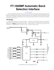
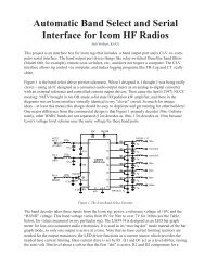
The <strong>Alpha</strong> <strong>76A</strong>. Yes, this is a<br />
lousy photograph.<br />
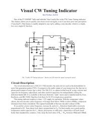
Photo 2. The rear panel has<br />
a factory-drilled hole above<br />
the T/R (RELAY) input.
I studied the protection schemes used in the Ameritron AL-1500 and the <strong>Alpha</strong> 91ß amplifiers. The AL-1500<br />
latches itself off-line if a grid current fault occurs. The lamps on one of the front panel meters darkens and operator<br />
must manually toggle the OPERATE/STANDBY switch to return to operation. The 91ß shuts off all power if<br />
plate current is excessive, and switches off-line for several seconds if grid current or reflected power is high, or if<br />
throughput gain is low. Its delay time may be circumvented by manually toggling its standby switch.<br />
The <strong>76A</strong> already has over-plate current shutdown, and a gain monitor is both <strong>com</strong>plicated and does not<br />
contribute much if grid current is watched. I did not want a reflected-power limit. This meant the only other<br />
feature necessary to keep my <strong>76A</strong> tubes happy and long-lived was automatic grid current monitoring. Since<br />
surgery was planned anyway, a proper solid-state T/R switch might as well be implemented to reduce the control<br />
switching requirements of the driving transmitter.<br />
Decisions, Decisions<br />
Once the goal was defined, several circuits were designed. One, a fully manual reset design, fires a transistor<br />
latch when high grid current flows and uses an external reset push button. Another uses an external box with a<br />
LM3914 LED bar graph driver that provides a moving display of grid current and fires a latch when the current<br />
pins the virtual meter. The manual reset circuit did not provide a visible indicator when the<br />
amplifier was switched off-line. The bar graph display circuit worked OK, but is a rather <strong>com</strong>plicated<br />
way to solve a simple problem. This <strong>com</strong>plexity is partially due to the way cut-off bias is<br />
implemented in the <strong>76A</strong>. In Standby mode (either via the front-panel “CW/SSB” switch or when<br />
the amplifier is in receive mode), both sides of the grid current sense resistor float at 28V above<br />
chassis. When activated, the grid (actually, the cathode) side drops to about 5V. While the<br />
LM3914 will operate under these conditions, I worry that basic amplifier operation might be<br />
affected by transient current flow during T/R switching after the proper amount of bypass capacitance<br />
is added. Both of these grid protection circuits required external wiring through the rearpanel<br />
AUX hole.<br />
The implemented design is of intermediate <strong>com</strong>plexity and requires no external wiring nor<br />
operator intervention. It uses <strong>com</strong>mon, unexciting parts in a straightforward circuit: an optoisolator,<br />
a venerable 555 timer, a voltage regulator, a low resistance N-channel power MOSFET, three<br />
low-cost bipolar transistors, and a few resistors and capacitors. Often, the most expensive portion<br />
of my designs are the connectors; this design requires none. This protection circuit does not<br />
affect amplifier operation in any way—until a grid current fault is detected.<br />
Da Design<br />
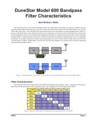
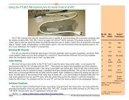
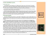
The circuit is shown in Figure 1. <strong>Grid</strong> current is detected by the 10Ω resistor (R116 on the <strong>76A</strong>’s High Voltage<br />
& Control PCB), and is fed to the optoisolator via R1. When the optoisolator reaches threshold, it triggers the 555<br />
timer (U2). This immediately forces the amplifier into standby mode and illuminates lamp B1. As long as the T/R<br />
line from the transmitter remains low, the amplifier remains latched off. Reset delay timing does not begin until<br />
this line pulls high (receive mode); this feature prevents hot switching the amplifier back on-line during a long<br />
transmission. Once the T/R line does go high, the short (switched in by Q2) across timing capacitor C1 is removed<br />
and the reset time interval begins. This interval is set by the product of Rt and C1. After it expires, the timer<br />
output drops low, B1 extinguishes and the amplifier is again ready for use. However, if the T/R line toggles low<br />
K6XX 2 <strong>Grid</strong> <strong>Protection</strong> for<strong>Alpha</strong> <strong>76A</strong> Amplifiers<br />
NCCC<br />
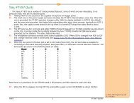
<strong>Protection</strong> Features<br />
1. High <strong>Grid</strong> Current<br />
<strong>Protection</strong><br />
2. Solid State T/R<br />
Switching (no relay, low<br />
switch resistance)<br />
3. Internal Installation (no<br />
external wires/switches,<br />
etc.)<br />
4. Automatic Reset after<br />
“Penalty” Delay<br />
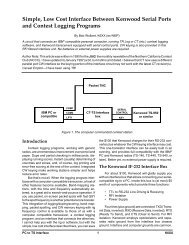
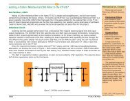
Photo 3. The innards. Rear<br />
panel at top, front panel at<br />
bottom. The 8874s live in<br />
the top left <strong>com</strong>partment.<br />
The Pi-L network is at the<br />
lower left. The RELAY jack<br />
is at top center, near the<br />
power transformer. The<br />
High Voltage & Control PCB<br />
covers the lower right<br />
quadrant.
NCCC<br />
<br />
Ω<br />
<br />
<br />
<br />
<br />
<br />
<br />
<br />
<br />
<br />
<br />
<br />
<br />
<br />
<br />
<br />
<br />
<br />
<br />
<br />
<br />
<br />
<br />
<br />
<br />
<br />
<br />
<br />
<br />
<br />
<br />
<br />
<br />
<br />
<br />
<br />
<br />
<br />
<br />
<br />
<br />
<br />
<br />
<br />
<br />
<br />
<br />
<br />
Figure 1. <strong>Grid</strong> Overcurrent Protect Circuit for <strong>Alpha</strong> 76, 374, and 78 Amplifiers.<br />
again DURING this interval, C1 is again discharged and the cycle is extended. Thus, an inattentive operator cannot<br />
repeatedly beat against those expensive grids. Hopefully, he will soon realize a fault has occurred and will pause to<br />
fix whatever is causing the problem.<br />
Drawbacks to this design include the lack of a manual reset—you must wait for the Rt x C1 time delay before<br />
the amplifier is again ready for use—and the fact that keying the amp during the delay interval resets the timer.<br />
On the other hand, you may set the interval time to whatever you choose. I use 0.68µF for C1 and 2.2MΩ for Rt.<br />
Delay time, D T<br />
, in seconds is set by<br />
D T<br />
= 1.1Rt x C1 (Either basic units or MΩ and µF)<br />
NOTE: Three-digit<br />
<strong>com</strong>ponent designations<br />
represent original <strong>Alpha</strong><br />
parts factory-installed<br />
inside the amplifier.<br />
K6XX 3 <strong>Grid</strong> <strong>Protection</strong> for<strong>Alpha</strong> <strong>76A</strong> Amplifiers
The grid overcurrent detect threshold is set by R1 working with the inherent forward<br />
voltage drop of the optoisolator (about 1.0 to 1.25V nominally). Since the optoisolator is<br />
operating at its threshold, the output load current represented by the 555 trigger pull-up<br />
resistor R2 is also important. 100kΩ is a good value for this resistor; if you use a different<br />
value, R1 might require adjustment. Further, as the amplifier heats up, the optoisolator<br />
threshold voltage drops a bit, which effectively drops the overcurrent detect limit. This drop<br />
is small because the optoisolator is located in the intake air stream, and does not significantly<br />
affect circuit performance. Remember, we are looking for fault protection; as long as<br />
the circuit allows normal grid currents of approximately 50 to 75mA and protects when this<br />
current reaches 150 to 200mA, all is satisfactory.<br />
The detect threshold current may be calculated as:<br />
I G(Shut-off)<br />
= 100 x R1(kΩ)<br />
Where I G<br />
is in mA and R1 in kΩ.<br />
An R1 value of 1.5kΩ resulted in a grid current threshold of 150mA. Using 2kΩ gave<br />
200mA. While a variable resistor may be used, it really isn’t necessary. I was tempted to use<br />
the 1.5kΩ resistor already on the control board (R117), but decided against it. If this resistor<br />
used, the internal grid current meter will provide inaccurately low readings due to the optoisolator loading it down.<br />
Construction and Installation<br />
My prototype was assembled using standard perfboard. The board is mounted on the rear panel of the amplifier<br />
through one slot of the ventilation air intake using a small bolt, washers and a nut (Photo 4). But before<br />
mounting it, disconnect the wire on the “RELAY” phono jack<br />
on the rear panel of the amplifier. This wire will connect to<br />
the new board, and the T/R line from the drain of Q1 replaces<br />
it on the jack. Four wires are routed to the <strong>76A</strong>’s High<br />
Voltage & Control PCB as shown in Photo 5. The current<br />
sense wires are tacked across R116, ensuring the anode side<br />
of the optoisolator goes to the R115 side of R116. Supply and<br />
ground connections are obtained by tapping across the 28V<br />
supply filter capacitor, C108. (NOTE: my schematic shows this<br />
is a 500µF capacitor, but my amplifier uses a 470µF—no<br />
worries, though!). One or two wires route the indicator bulb<br />
B1 up behind one of the translucent meter faces so it is<br />
visible when it illuminates.<br />
NCCC<br />
Photo 5. Control PCB, with<br />
front panel at bottom. The<br />
<strong>com</strong>ponents we hook onto<br />
are on the left side of the<br />
board. Indicator lamp B1<br />
(not shown) should rest<br />
against the transluscent<br />
face of one of the meters<br />
(bottom). Ensure all wires<br />
are well insulated since<br />
those exposed bolt heads<br />
and 2W resistors are high<br />
voltage points!<br />
Operation<br />
After installation, the top cover was reinstalled and the<br />
amp fired up. Normal operation at full power was verified,<br />
Photo 4. The board is installed on the rear panel then the loading control was purposefully mistuned. As the<br />
between the power transformer and the tube<br />
grid current hit 150mA (full scale on the internal meter), the<br />
<strong>com</strong>partment.<br />
amp kicked off-line. After a couple of seconds, the transmitter<br />
K6XX 4 <strong>Grid</strong> <strong>Protection</strong> for<strong>Alpha</strong> <strong>76A</strong> Amplifiers
was keyed with lower drive. The amplifier responded by amplifying until the increasing drive again caused the grid<br />
current to exceed 150mA, where it again kicked off. Maintaining key-down on the transmitter, the amplifier remained<br />
off-line. Toggling the T/R line with receive periods less than about a second kept the amp off-line, but as<br />
soon as a receive period exceeding a second and a half or so occurred, the amplifier was rearmed and ready to try<br />
again, just as expected. Imagine that!<br />
No RF susceptibility problems have yet been detected.<br />
Circuit Additions<br />
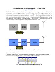
This basic circuit may be expanded if further protection parameters are desired. Since reflected power measurement<br />
is already provided by the amplifier, it may be added to the protective parameters with a <strong>com</strong>parator, a<br />
few resistors and a diode. Figure 2 shows a possible configuration.<br />
When the reflected power rises, the watt meter’s reflected power bridge outputs an increasing current to RRa<br />
and RRb. This level is <strong>com</strong>pared to the voltage set by R A<br />
and R B<br />
. If the reflected power is too high, the <strong>com</strong>parator<br />
switches high, which triggers the 555 timer through D1. The remainder of the protection circuit functions the same<br />
as before.<br />
Another important parameter is exhaust air temperature. This might be implemented with another <strong>com</strong>parator<br />
and a temperature sensor, either silicon or bimetallic. On the other hand, if the exhaust air is too hot, a much<br />
longer delay time is probably warranted!<br />
NCCC<br />
<br />
<br />
<br />
<br />
<br />
<br />
<br />
<br />
<br />
<br />
Figure 2. Adding High Reflected Power <strong>Protection</strong><br />
Conclusion<br />
While I’m sure that some day my 8874s will bite the dust, I believe that day has been delayed a bit by the<br />
inclusion of overcurrent protection. I am working on a clean PC board version of this circuit. Is anyone interested<br />
K6XX 5 <strong>Grid</strong> <strong>Protection</strong> for<strong>Alpha</strong> <strong>76A</strong> Amplifiers<br />
Text and circuit design<br />
©2005, 2006 R.P Wolbert<br />
and 26K Engineering<br />
Ver 1.1 27Feb06