User's Manual - Allied Vision Technologies
User's Manual - Allied Vision Technologies
User's Manual - Allied Vision Technologies

You also want an ePaper? Increase the reach of your titles
YUMPU automatically turns print PDFs into web optimized ePapers that Google loves.
Item 1: GIGABIT ETHERNET PORT<br />
This port conforms to the IEEE 802.3 1000BASE-T standard for Gigabit Ethernet over copper. It is<br />
recommended that CAT5E or CAT6 compatible cabling and connectors be used for best<br />
performance. Cable lengths up to 100m are supported.<br />
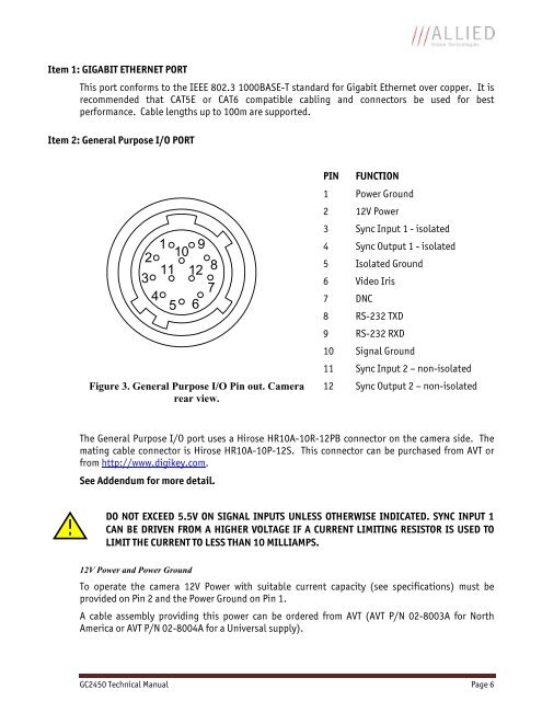
Item 2: General Purpose I/O PORT<br />
1 9<br />
2<br />
10<br />
11 12 8<br />
3<br />
7<br />
4<br />
5 6<br />
Figure 3. General Purpose I/O Pin out. Camera<br />
rear view.<br />
PIN FUNCTION<br />
1 Power Ground<br />
2 12V Power<br />
3 Sync Input 1 - isolated<br />
4 Sync Output 1 - isolated<br />
5 Isolated Ground<br />
6 Video Iris<br />
7 DNC<br />
8 RS-232 TXD<br />
9 RS-232 RXD<br />
10 Signal Ground<br />
11 Sync Input 2 – non-isolated<br />
12 Sync Output 2 – non-isolated<br />
The General Purpose I/O port uses a Hirose HR10A-10R-12PB connector on the camera side. The<br />
mating cable connector is Hirose HR10A-10P-12S. This connector can be purchased from AVT or<br />
from http://www.digikey.com.<br />
See Addendum for more detail.<br />
DO NOT EXCEED 5.5V ON SIGNAL INPUTS UNLESS OTHERWISE INDICATED. SYNC INPUT 1<br />
CAN BE DRIVEN FROM A HIGHER VOLTAGE IF A CURRENT LIMITING RESISTOR IS USED TO<br />
LIMIT THE CURRENT TO LESS THAN 10 MILLIAMPS.<br />
12V Power and Power Ground<br />
To operate the camera 12V Power with suitable current capacity (see specifications) must be<br />
provided on Pin 2 and the Power Ground on Pin 1.<br />
A cable assembly providing this power can be ordered from AVT (AVT P/N 02-8003A for North<br />
America or AVT P/N 02-8004A for a Universal supply).<br />
GC2450 Technical <strong>Manual</strong> Page 6