User's Manual - Allied Vision Technologies
User's Manual - Allied Vision Technologies
User's Manual - Allied Vision Technologies

You also want an ePaper? Increase the reach of your titles
YUMPU automatically turns print PDFs into web optimized ePapers that Google loves.
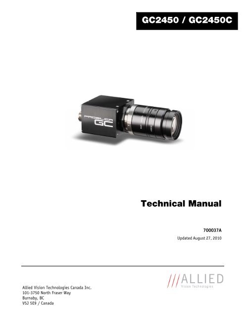
GC2450 / GC2450C<br />
Technical <strong>Manual</strong><br />
700037A<br />
Updated August 27, 2010<br />
<strong>Allied</strong> <strong>Vision</strong> <strong>Technologies</strong> Canada Inc.<br />
101-3750 North Fraser Way<br />
Burnaby, BC<br />
V5J 5E9 / Canada
Table of Contents<br />
Table of Contents .......................................................................................................... ii<br />
Introduction ............................................................................................................ 1<br />
Precautions.............................................................................................................. 1<br />
Warranty ................................................................................................................. 1<br />
Specifications .......................................................................................................... 2<br />
Supported Features ................................................................................................... 3<br />
Mechanical .............................................................................................................. 4<br />
Connections ............................................................................................................. 5<br />
Cleaning the Sensor ................................................................................................... 9<br />
Adjusting the C-mount .............................................................................................. 10<br />
Camera Installation .................................................................................................. 11<br />
System Optimization ................................................................................................. 16<br />
Trouble Shooting ..................................................................................................... 18<br />
Addendum .................................................................................................................. 21<br />
GC IO Schematic ....................................................................................................... 22<br />
Isolated Trigger Schematic ......................................................................................... 23<br />
Non-isolated Trigger Schematic .................................................................................. 24<br />
Video Iris Schematic ................................................................................................. 25<br />
Trigger Timing Diagram ............................................................................................. 26<br />
Notes on Triggering .................................................................................................. 27<br />
GC2450 Technical <strong>Manual</strong><br />
Page ii
Legal notice<br />
For customers in the U.S.A.<br />
(FCC Compliance Information)<br />
This equipment has been tested and found to comply with the limits for a Class A digital device, pursuant to Part 15 of the FCC Rules.<br />
These limits are designed to provide reasonable protection against harmful interference when the equipment is operated in a<br />
commercial environment. This equipment generates, uses, and can radiate radio frequency energy and, if not installed and used in<br />
accordance with the instruction manual, may cause harmful interference to radio communications. However there is no guarantee<br />
that interferences will not occur in a particular installation. Operation of this equipment in a residential environment is likely to<br />
cause harmful interference.<br />
You are cautioned that any changes or modifications not expressly approved in this manual could void your authority to operate this<br />
equipment. The shielded interface cable recommended in this manual must be used with this equipment in order to comply with the<br />
limits for a computing device pursuant to Subpart B of Part 15 of FCC Rules.<br />
For customers in Canada<br />
This digital apparatus complies with the Class A limits for radio noise emissions set out in the Radio Interference Regulations.<br />
Pour utilisateurs au Canada<br />
Cet appareil numérique est conforme aux normes classe A pour bruits radioélectriques, spécifiées dans le Règlement sur le<br />
brouillage radioélectrique.<br />
Life support applications<br />
These products are not designed for use in life support appliances, devices, or systems where malfunction of these products can<br />
reasonably be expected to result in personal injury. <strong>Allied</strong> <strong>Vision</strong> <strong>Technologies</strong> customers using or selling these products for use in<br />
such applications do so at their own risk and agree to fully indemnify <strong>Allied</strong> <strong>Vision</strong> <strong>Technologies</strong> for any damages resulting from<br />
such improper use or sale.<br />
Trademarks<br />
Unless stated otherwise, all trademarks appearing in this document are the property of <strong>Allied</strong> <strong>Vision</strong> <strong>Technologies</strong> and are fully<br />
protected by law.<br />
Warranty<br />
The information provided by <strong>Allied</strong> <strong>Vision</strong> <strong>Technologies</strong> is supplied without any guarantees or warranty whatsoever, be it specific or<br />
implicit. Also excluded are all implicit warranties concerning the negotiability, the suitability for specific applications or the nonbreaking<br />
of laws and patents. Even if we assume that the information supplied to us is accurate, errors and inaccuracy may still<br />
occur.<br />
Copyright<br />
All text, pictures and graphics are protected by copyright and other laws protecting intellectual property. It is not permitted to copy<br />
or modify them for trade use or transfer, nor may they be used on web sites.<br />
<strong>Allied</strong> <strong>Vision</strong> <strong>Technologies</strong> Canada Inc. 1/2010<br />
All rights reserved.<br />
GC2450 Technical <strong>Manual</strong><br />
Page iii
Contacting <strong>Allied</strong> <strong>Vision</strong> <strong>Technologies</strong><br />
• Technical information:<br />
http://www.alliedvisiontec.com<br />
• Support:<br />
support@alliedvisiontec.com<br />
<strong>Allied</strong> <strong>Vision</strong> <strong>Technologies</strong> GmbH (Headquarters)<br />
Taschenweg 2a<br />
07646 Stadtroda, Germany<br />
Tel.: +49.36428.677-0<br />
Fax.: +49.36428.677-28<br />
e-mail: info@alliedvisiontec.com<br />
<strong>Allied</strong> <strong>Vision</strong> <strong>Technologies</strong> Canada Inc.<br />
101-3750 North Fraser Way<br />
Burnaby, BC, V5J 5E9, Canada<br />
Tel: +1 604-875-8855<br />
Fax: +1 604-875-8856<br />
e-mail: info@alliedvisiontec.com<br />
<strong>Allied</strong> <strong>Vision</strong> <strong>Technologies</strong> Inc.<br />
38 Washington Street<br />
Newburyport, MA 01950, USA<br />
Toll Free number +1-877-USA-1394<br />
Tel.: +1 978-225-2030<br />
Fax: +1 978-225-2029<br />
e-mail: info@alliedvisiontec.com<br />
GC2450 Technical <strong>Manual</strong><br />
Page iv
Introduction<br />
The GC2450 series of cameras are 5 megapixel, 15 frames per second, Gigabit Ethernet cameras<br />
based on the Sony ICX625ALA and ICX625AQA, Super HAD CCD sensors.<br />
Precautions<br />
READ INSTALLATION GUIDE CAREFULLY.<br />
This document contains specific information which is necessary for the correct operation and<br />
treatment of this product.<br />
DO NOT OPEN THE CAMERA. WARRANTY IS VOID IF CAMERA IS OPENED.<br />
This camera contains sensitive components which can be damaged if handled incorrectly.<br />
KEEP SHIPPING MATERIAL.<br />
Poor packaging of this product can cause damage during shipping.<br />
VERIFY ALL EXTERNAL CONNECTIONS.<br />
Verify all external connections in terms of voltage levels, power requirements, voltage polarity,<br />
and signal integrity prior to powering this device.<br />
CLEANING.<br />
This product can be damaged by some volatile cleaning agents. Avoid cleaning the image sensor<br />
unless absolutely necessary. Please see instructions on sensor cleaning in this document.<br />
DO NOT EXCEED ENVIRONMENTAL SPECIFICATIONS.<br />
See environmental specifications limits in the Specifications section of this document.<br />
Warranty<br />
AVT provides a 2 year warranty which covers the replacement and repair of all AVT parts which are<br />
found to be defective in the normal use of this product. AVT will not warranty parts which have<br />
been damaged through the obvious misuse of this product.<br />
GC2450 Technical <strong>Manual</strong> Page 1
Specifications<br />
Sensor Type<br />
Sony ICX625ALA CCD (ICX625AQA for color)<br />
Sensor Shutter Type<br />
Progressive Interline<br />
Image Resolution<br />
2448 x 2050 pixels<br />
Pixel Size<br />
3.45μm x 3.45μm<br />
Optical Format<br />
2/3 inch<br />
Lens Mount<br />
C-mount with adjustable back focus<br />
Color Sensor Filter Pattern †<br />
Bayer<br />
Full Resolution Frame Rate<br />
15.1 fps<br />
Frame Rate (1900 x 1080 ROI) 24.6 fps<br />
I/O<br />
1 isolated input/output, 1 non-isolated input/output,<br />
1 RS-232 input/output<br />
Power Requirements Less than 3.8W †† (5V to 16V) †††<br />
Digitization<br />
12 Bits<br />
Trigger latency*<br />
2us for non-isolated I/O, 10us for isolated I/O<br />
Trigger Jitter*<br />
±20ns for non-isolated I/O, ±0.5us for isolated I/O<br />
Tpd*<br />
10ns for non-isolated I/O, 1.3us for isolated I/O<br />
Operating Temperature<br />
0 to 40 Celsius***<br />
Operating Humidity<br />
20 to 80% non-condensing<br />
Size<br />
33mm (height) x 46mm (width) x 59mm (length)<br />
Weight<br />
106g<br />
Hardware Interface Standard IEEE 802.3 1000BASE-T, 100BASE-TX<br />
Software Interface Standard GigE <strong>Vision</strong> Standard 1.0<br />
Regulatory<br />
CE, FCC, RoHS<br />
† Applies to GC2450C only.<br />
†† Power consumption will increase with reduced ROI imaging and color interpolation.<br />
††† Nominal operating voltage is 12V. Cameras have been tested at 12V.<br />
* See Notes on Triggering in the Addendum.<br />
***DUE TO THE SMALL PACKAGING AND HIGH SPEED OF THE GC CAMERAS, SPECIAL CARE IS REQUIRED TO<br />
MAINTAIN A REASONABLE OPERATING TEMPERATURE. IF THE CAMERA IS TO BE OPERATED IN A WARM<br />
ENVIRONMENT, IT IS SUGGESTED THAT THE CAMERA BE MOUNTED ON A HEAT SINK SUCH AS A METAL BRACKET<br />
AND THAT THERE IS SUFFICIENT AIR FLOW.<br />
GC2450 Technical <strong>Manual</strong> Page 2
Supported Features<br />
Imaging Modes<br />
free-running, external trigger, fixed rate, software trigger<br />
Fixed Rate Control 0.001 fps to maximum frame rate<br />
External Trigger Delay 0 to 60 seconds in 1 microsecond increments<br />
External Trigger Event rising edge, falling edge, any edge, level high, level low<br />
Exposure Time<br />
25 microseconds to 60 seconds in 1 microsecond increments<br />
Gain<br />
0 to 24dB<br />
Region of Interest (ROI) independent x and y control with 1 pixel resolution<br />
Horizontal Binning 1 to 8 pixels<br />
Vertical Binning 1 to 14 rows<br />
Pixel Formats Mono8*, Mono16*, Bayer8, Bayer 16<br />
Sync Out Modes<br />
trigger ready, trigger input, exposing, readout, imaging, strobe, GPO<br />
*On monochrome versions only.<br />
GC2450 Technical <strong>Manual</strong> Page 3
Mechanical<br />
Figure 1. GC SERIES mechanical dimensions.<br />
GC2450 Technical <strong>Manual</strong> Page 4
Connections<br />
4<br />
2<br />
3<br />
1<br />
Figure 2. GC SERIES connection diagram.<br />
GC2450 Technical <strong>Manual</strong> Page 5
Item 1: GIGABIT ETHERNET PORT<br />
This port conforms to the IEEE 802.3 1000BASE-T standard for Gigabit Ethernet over copper. It is<br />
recommended that CAT5E or CAT6 compatible cabling and connectors be used for best<br />
performance. Cable lengths up to 100m are supported.<br />
Item 2: General Purpose I/O PORT<br />
1 9<br />
2<br />
10<br />
11 12 8<br />
3<br />
7<br />
4<br />
5 6<br />
Figure 3. General Purpose I/O Pin out. Camera<br />
rear view.<br />
PIN FUNCTION<br />
1 Power Ground<br />
2 12V Power<br />
3 Sync Input 1 - isolated<br />
4 Sync Output 1 - isolated<br />
5 Isolated Ground<br />
6 Video Iris<br />
7 DNC<br />
8 RS-232 TXD<br />
9 RS-232 RXD<br />
10 Signal Ground<br />
11 Sync Input 2 – non-isolated<br />
12 Sync Output 2 – non-isolated<br />
The General Purpose I/O port uses a Hirose HR10A-10R-12PB connector on the camera side. The<br />
mating cable connector is Hirose HR10A-10P-12S. This connector can be purchased from AVT or<br />
from http://www.digikey.com.<br />
See Addendum for more detail.<br />
DO NOT EXCEED 5.5V ON SIGNAL INPUTS UNLESS OTHERWISE INDICATED. SYNC INPUT 1<br />
CAN BE DRIVEN FROM A HIGHER VOLTAGE IF A CURRENT LIMITING RESISTOR IS USED TO<br />
LIMIT THE CURRENT TO LESS THAN 10 MILLIAMPS.<br />
12V Power and Power Ground<br />
To operate the camera 12V Power with suitable current capacity (see specifications) must be<br />
provided on Pin 2 and the Power Ground on Pin 1.<br />
A cable assembly providing this power can be ordered from AVT (AVT P/N 02-8003A for North<br />
America or AVT P/N 02-8004A for a Universal supply).<br />
GC2450 Technical <strong>Manual</strong> Page 6
Sync Input 1 and Sync Input 2<br />
These input signals allow the camera to be synchronized to some external event. The camera can<br />
be programmed to trigger on the rising edge, falling edge, both edges or level of this signal. The<br />
camera can also be programmed to capture an image at some programmable delay time after the<br />
trigger event.<br />
Sync Input 1 is isolated and should be used in noisy environments to prevent false triggering due<br />
to ground loop noise. Sync Input 2 is non-isolated and can be used when a faster trigger is<br />
required and when environmental noise is not a problem.<br />
Sync Output 1 and Sync Output 2<br />
These signals only function as outputs and can be configured as follows:<br />
Exposing<br />
Trigger Ready<br />
Trigger Input<br />
Readout<br />
Imaging<br />
Strobe<br />
GPO<br />
Corresponds to when camera is<br />
integrating light.<br />
Indicates when the camera will accept a<br />
trigger signal.<br />
A relay of the trigger input signal used to<br />
“daisy chain” the trigger signal for<br />
multiple cameras.<br />
Valid when camera is reading out data.<br />
Valid when camera is exposing or reading<br />
out.<br />
Programmable pulse based on one of the<br />
above events.<br />
User programmable binary output.<br />
Any of the above signals can be set for active high or active low.<br />
Sync Output 1 will require a pull up resistor of greater than 1Kohm to the user’s 5V logic supply.<br />
Sync Output 1 is isolated and should be used in noisy environments. Sync Output 2 is non-isolated<br />
and can be used when environmental noise is not a problem and when faster response is required.<br />
RS-232 RXD and RS-232 TXD<br />
These signals are RS-232 compatible. These signals allow communication from the host system via<br />
the Ethernet port to a peripheral device connected to the camera. Note that these signals are not<br />
isolated and therefore careful attention should be used when designing cabling in noisy<br />
environments.<br />
GC2450 Technical <strong>Manual</strong> Page 7
Isolated Ground<br />
Isolated Ground must be connected to the user’s external circuit ground if Sync Input 1 or Sync<br />
Output 1 is to be used.<br />
Signal Ground<br />
Signal Ground must be connected to the user’s external circuit ground if Sync Input 2 or Sync<br />
Output 2 is to be used or if the RS-232 port is to be used. Note that Signal Ground is common with<br />
Power Ground however it is good practice to provide a separate ground connection for power and<br />
signaling when designing the cabling.<br />
Video Iris<br />
This signal can be used to drive the video input of a video iris lens. See Addendum.<br />
DNC<br />
These signals are reserved for future use and should be left disconnected.<br />
Item 3: Status LED 1<br />
LED COLOR STATUS<br />
Solid Orange<br />
Ethernet link established.<br />
Flashing Orange<br />
Ethernet activity.<br />
Item 4: Status LED 2<br />
LED COLOR STATUS<br />
Solid Green Normal operation.<br />
Flashing once per second Boot up pending<br />
3 quick flashes once per Camera fault.<br />
second.<br />
GC2450 Technical <strong>Manual</strong> Page 8
Cleaning the Sensor<br />
DO NOT CONTACT CLEAN SENSOR UNLESS ABSOLUTELY NECESSARY.<br />
Identifying Debris<br />
Debris on the image sensor or optical components will appear as a darkened area or smudge on the<br />
image that does not move as the camera is moved. Do not confuse this with a pixel defect which<br />
will appear as a distinct point.<br />
Locating Debris<br />
Before attempting to clean the image sensor, it is important to first determine that the problem is<br />
due to debris on the sensor window. To do this you should be viewing a uniform image, such as a<br />
piece of paper, with the camera. Debris will appear as a dark spot or dark region that does not<br />
move as the camera is moved. To determine that the debris is not on the camera lens, rotate the<br />
lens independent of the camera. If the spot moves as the lens moves, then the object is on the<br />
lens -not on the image sensor- and therefore cleaning is not required. If the camera has an IR<br />
filter, then rotate the IR filter. If the object moves then the particle is on the IR filter not the<br />
sensor. If this is the case remove the IR filter carefully using a small flat head screw driver. Clean<br />
both sides of the IR filter using the same techniques as explained below for the sensor window.<br />
DO NOT TOUCH ANY OPTICS WITH FINGERS. OIL FROM FINGERS CAN DAMAGE FRAGILE<br />
OPTICAL COATINGS.<br />
Cleaning with Air<br />
If it is determined that debris is on the sensor window, then remove the camera lens, and blow the<br />
sensor window directly with clean compressed air. If canned air is used, do not shake or tilt the<br />
can prior to blowing the sensor. View a live image with the camera after blowing. If the debris is<br />
still there, repeat this process. Repeat the process a number of times with increased intensity until<br />
it is determined that the particulate cannot be dislodged. If this is the case then proceed to the<br />
contact cleaning technique.<br />
Contact Cleaning<br />
Only use this method as a last resort. Use 99% laboratory quality isopropyl alcohol and clean<br />
cotton swabs. Dampen the swab in the alcohol and gently wipe the sensor in a single stroke. Do<br />
not reuse the same swab. Do not wipe the sensor if the sensor and swab are both dry. You must<br />
wipe the sensor quickly after immersion in the alcohol, or glue from the swab will contaminate the<br />
sensor window. Repeat this process until the debris is gone. If this process fails to remove the<br />
debris, then contact AVT.<br />
GC2450 Technical <strong>Manual</strong> Page 9
Adjusting the C-mount<br />
LOCKING RING<br />
C-MOUNT RING<br />
Figure 4. Camera Front View.<br />
THE C-MOUNT IS ADJUSTED AT THE FACTORY AND SHOULD NOT REQUIRE ADJUSTING.<br />
If for some reason, the C-mount requires adjustment, use the following method.<br />
Loosen Locking Ring<br />
Use an adjustable wrench to loosen locking ring. Be careful not to scratch the camera. When the<br />
locking ring is loose, unthread the ring a few turns from the camera face. A wrench suitable for this<br />
procedure can be provided by AVT (P/N 11-0048A).<br />
Image to Infinity<br />
Use a c-mount compatible lens that allows an infinity focus. Set the lens to infinity and image a<br />
distant object. The distance required will depend on the lens used but typically 30 to 50 feet<br />
should suffice. Make sure the lens is firmly threaded onto the c-mount ring. Rotate the lens and c-<br />
mount ring until the image is focused. Carefully tighten locking ring. Recheck focus.<br />
GC2450 Technical <strong>Manual</strong> Page 10
Camera Installation<br />
Computer Interface<br />
The Prosilica GC cameras will work with any Ethernet network card; however AVT strongly<br />
recommends using Gigabit Ethernet components that support Jumbo Frames. A Jumbo Frame is<br />
loosely defined as a frame size greater than 1500 bytes however typical Jumbo Frames are around<br />
9000 bytes. Frame size is the number of bytes per packet and the larger the frame size, the less the<br />
computer CPU will be loaded due to the processing of incoming packets.<br />
There are many Gigabit Ethernet cards available which will support Jumbo Frames. The following<br />
examples have been verified to work well with the Prosilica GC cameras:<br />
• Intel PRO/1000<br />
• D-Link DGE-550T<br />
• SMC EZ Card 1000<br />
Gigabit Ethernet cards supporting this feature can also be purchased with the camera (AVT P/N 02-<br />
3002A).<br />
GC2450 Technical <strong>Manual</strong> Page 11
Gigabit Ethernet Setup for Windows<br />
o Install network card in computer.<br />
o Boot the PC and cancel the “Found new Hardware Wizard” window that may appear when<br />
Windows detects the new card.<br />
o Install the driver that came with the network card.<br />
o Once the driver is installed, open the Network Connections Dialog as follows: From the<br />
Windows desktop select start, then select Control Panel, then double click on the Network<br />
Connections icon. Double click the relevant network card listed or right-click the relevant<br />
network card and select Properties. This will open the properties window for your network<br />
card. See Figure 5.<br />
Figure 5. Network card main properties window.<br />
GC2450 Technical <strong>Manual</strong> Page 12
o Select the Internet Protocol (TCP/IP) check box and then select Properties. See Figure 6.<br />
Network card TCP/IP address.. Select the Use the following IP address and enter an IP<br />
address of 169. 254. x. y, where x and y can be any number. Press the TAB key after entering<br />
the IP address and the subnet mask will automatically be entered. The subnet mask is 255.<br />
255. 0. 0. Click OK to save changes. Note that if Windows reports a conflict with the above IP<br />
address, simply repeat the above steps and change the last digit of the IP address to a different<br />
value.<br />
Figure 6. Network card TCP/IP address.<br />
GC2450 Technical <strong>Manual</strong> Page 13
Figure 7. Turn off Firewall.<br />
o Return to the Gige Local Properties window as in Figure 5. Select the Advanced tab as in<br />
Figure 7 and disable the Firewall for this device. Click OK to save changes.<br />
Gigabit Ethernet Cabling<br />
All Gigabit Ethernet cabling and connectors should be CAT5E or CAT6 compatible. Cable lengths<br />
must not exceed 100 meters.<br />
Power Connection<br />
The camera requires a 12V DC power supply that can source a minimum of 500 mA of current. See<br />
the Connections section of this document for more information.<br />
GC2450 Technical <strong>Manual</strong> Page 14
Installing GigE Viewer for Testing<br />
o The latest Viewer software can be downloaded from<br />
http://www.alliedvisiontec.com/us/support.html.<br />
o Run the GigE Viewer Installer.exe. This will install the Prosilica GC Digital Camera drivers as<br />
well as the GigE Viewer application program.<br />
o Plug in the Prosilica GC camera via the Gigabit Ethernet port. Plug in the power connection.<br />
Verify that the Status LED 2 is a solid green. Run the GigE Viewer Application. It will take a few<br />
seconds for the camera to be recognized. If the camera does not appear in the Viewer list after<br />
approximately 10 seconds then try disconnecting and reconnecting the power. If it still does<br />
not appear restart the viewer. If it still does not appear, see the Trouble Shooting section of<br />
this document.<br />
o See Figure 8. Select the wrench icon to change camera settings. Change the PacketSize to a<br />
value of 1500. Select the eye icon to image. The camera should now be imaging. If the<br />
camera is not imaging, see the Trouble Shooting section of this document. Note that the<br />
PacketSize can be set to 8228 if the network card has been optimized to support jumbo frames.<br />
o See the System Optimization Section to maximize the performance of your system.<br />
Figure 8. GigE Viewer application window.<br />
GC2450 Technical <strong>Manual</strong> Page 15
System Optimization<br />
o Open the Network Connections Dialog as follows: From the Windows desktop select start, then<br />
select Control Panel, then double click on the Network Connections icon. Double click the<br />
relevant network card listed or right-click the relevant network card and select Properties.<br />
This will open the properties window for your network card. See Figure 9.<br />
Figure 9. Network card main properties window.<br />
o From the Properties window select Configure then select the Advanced tab. See Figure 10.<br />
GC2450 Technical <strong>Manual</strong> Page 16
Figure 10. Network card advanced settings.<br />
o Set Maximum Frame Size or Jumbo Frames to the maximum possible value. A typical value is<br />
9000. If the list contains a property called Receive Descriptors, then change this value to its<br />
maximum value. Select OK to save properties.<br />
o From the main properties dialog as in Figure 9, make sure that only the Internet Protocol<br />
(TCP/IP) check box is selected then click OK. The card is now optimized for use with the<br />
Prosilica GC camera.<br />
o Open the viewer and set the PacketSize to 8228.<br />
GC2450 Technical <strong>Manual</strong> Page 17
Trouble Shooting<br />
Is the camera getting power<br />
The right LED is the camera power indicator. If unlit, check the power adaptor. If possible, swap<br />
with one that is known to work. If using a custom power adaptor, be sure the adaptor and wire<br />
gauge is rated to at least 500 mA. If the right LED still does not light up, contact AVT support.<br />
Is the camera powered, but not detected in SampleViewer<br />
Damaged or poor quality Ethernet cabling can result in no cameras found, dropped packets,<br />
decreased bandwidth, and other problems. Use Cat5e or better cabling known to work.<br />
Configure your NIC as outlined in “Gigabit Ethernet Setup For Windows”. It should have an IP<br />
address of 169.254.x.x, Subnet Mask: 255.255.0.0. This is the AutoIP address range. If your NIC<br />
has no access to a DHCP server, the camera will still be auto assigned an IP address. There should<br />
be no gateway on your NIC.<br />
Connect a single camera directly to your NIC, no hub/switch, and run the AVT IP Configuration<br />
utility (Start>Programs>prosilica>GigEIPConfig or C:\Program<br />
Files\prosilica\GigEViewer\ipconfig.exe). You may need to wait up to 30 sec for camera to appear.<br />
A camera in DHCP (AutoIP fallback) mode.<br />
• Camera is listed: Your camera and NIC must be on the same subnet, e.g.: NIC: IP<br />
169.254.23.2 Subnet Mask: 255.255.0.0, Camera IP: 169.254.43.3 Subnet Mask: 255.255.0.0.<br />
The following example is not on the same Subnet: NIC IP 169.250.23.2 Subnet Mask:<br />
255.255.255.0, CamIP 169.254.13.0 Subnet Mask: 255.255.0.0. This can happen if you use a non<br />
AutoIP range on your NIC and it doesn’t have access to a DHCP server. Either change your NIC IP to<br />
be in the AutoIP range, or fix the camera IP address to be on the same subnet as your NIC.<br />
GC2450 Technical <strong>Manual</strong> Page 18
• Camera is not listed, or flashing “Camera Unavailable”: There may be multiple NICs on your<br />
system set to the same subnet. The camera can not know which card to resolve to. Change the IP<br />
address of your NIC.<br />
If you are still having problems, type: ipconfig /all in a windows command prompt, and send a<br />
screenshot to AVT support.<br />
Ipconfig /all screenshot<br />
Is the camera listed in SampleViewer but can’t acquire images<br />
Reset your camera settings to factory default: with ConfigFileIndex = Factory, click the<br />
ConfigFileLoad button.<br />
While streaming, check your Stats:<br />
GC2450 Technical <strong>Manual</strong> Page 19
All stats 0 while streaming. Firewall likely blocking traffic<br />
• All stats 0. Likely a firewall is blocking incoming traffic. Disable your firewall. Check your<br />
camera trigger settings. Many camera trigger modes require a software or hardware trigger<br />
event to capture frames.<br />
• Packets are incoming, but all dropping. Be sure you have JumboFrames enabled on your<br />
NIC. Otherwise, decrease your PacketSize setting to 1500.<br />
• All packets completing as normal, but black image. Check ExposureValue, ExposureMode,<br />
and be sure your scene is suitably lit.<br />
If you are still having problems acquiring images, please send your camera settings file (click on the<br />
disk icon in SampleViewer) to AVT support.<br />
Saving camera setting file<br />
GC2450 Technical <strong>Manual</strong> Page 20
Addendum<br />
GC2450 Technical <strong>Manual</strong> Page 21
GC IO Schematic<br />
AS SEEN FROM<br />
CAMERA REAR VIEW<br />
1 9<br />
2 10 8<br />
3<br />
7<br />
11 12<br />
4<br />
6<br />
5<br />
1<br />
2<br />
3<br />
4<br />
5<br />
6<br />
7<br />
8<br />
9<br />
10<br />
11<br />
12<br />
POWER GROUND<br />
12V POWER<br />
SYNC INPUT 1<br />
SYNC OUTPUT 1<br />
ISOLATED GROUND<br />
RS232-TXD<br />
RS232-RXD<br />
SYNC INPUT 2<br />
SYNC OUTPUT 2<br />
SYNC INPUT 1<br />
ISOLATED GROUND<br />
VDD-3.3<br />
390R<br />
1/8W<br />
200R<br />
FAIRCHILD<br />
MOCD207M<br />
1<br />
2<br />
3<br />
4<br />
8<br />
7<br />
6<br />
5<br />
VDD-3.3<br />
SYNC OUTPUT 1<br />
2K<br />
CAMERA INTERNAL CIRCUIT<br />
LOGIC SYNC INPUT 1<br />
HIROSE HR10A-10R-12PB<br />
LOGIC SYNC OUTPUT 1<br />
0.1u<br />
0.1u<br />
0.1u<br />
0.1u<br />
1<br />
2<br />
3<br />
4<br />
5<br />
6<br />
7<br />
MAXIM<br />
MAX3221CPWR<br />
EN<br />
C1+<br />
V+<br />
C1-<br />
C2+<br />
C2-<br />
V-<br />
FORCEOFF<br />
VCC<br />
GND<br />
DOUT<br />
FORCEON<br />
DIN<br />
INVALID<br />
16<br />
15<br />
14<br />
13<br />
12<br />
11<br />
10<br />
8 9<br />
RIN<br />
ROUT<br />
VDD-3.3<br />
RS232-TXD<br />
LOGIC TXD<br />
LOGIC RXD<br />
RS232-RXD<br />
SYNC OUTPUT 2<br />
SYNC INPUT 2<br />
VDD-3.3<br />
8<br />
7<br />
6<br />
5<br />
TEXAS INSTRUMENTS<br />
SN74LVC2G241DCU<br />
VCC<br />
2OE<br />
1Y<br />
2A<br />
1OE<br />
1A<br />
2Y<br />
GND<br />
1<br />
2<br />
3<br />
4<br />
LOGIC SYNC OUTPUT 2<br />
LOGIC SYNC INPUT 2<br />
GC2450 Technical <strong>Manual</strong> Page 22
Isolated Trigger Schematic<br />
USERS TRIGGER CIRCUIT<br />
CABLE SIDE<br />
POWER GROUND<br />
12V_POWER<br />
SYNC INPUT 1 (DRIVER)<br />
R1<br />
POWER GROUND<br />
12V POWER<br />
SYNC INPUT 1<br />
SYNC OUTPUT 1<br />
ISOLATED GROUND<br />
1<br />
2<br />
3<br />
4<br />
5<br />
6<br />
7<br />
8<br />
9<br />
10<br />
11<br />
12<br />
9 1<br />
8 10<br />
7<br />
6<br />
12 11<br />
5<br />
2<br />
3<br />
4<br />
USER POWER<br />
HIROSE HR10A-10P-12S<br />
SYNC OUTPUT 1 (RECEIVER)<br />
R2<br />
USER<br />
POWER<br />
5V<br />
RECOMMENDED VALUES<br />
R1 R2<br />
0 1K<br />
12V<br />
0.7K<br />
2.7K<br />
24V<br />
1.8K<br />
4.7K<br />
This circuit assumes a 10mA drive current (I F ) from User’s trigger circuit into camera through R1. R2 is connected to the open collector of<br />
Fairchild MOCD207. The corresponding transistor emitter is connected to isolated ground. See the Fairchild MOCD207 datasheet for more<br />
detailed information.<br />
GC2450 Technical <strong>Manual</strong> Page 23
Non-isolated Trigger Schematic<br />
USERS TRIGGER CIRCUIT<br />
CABLE SIDE<br />
POWER GROUND<br />
12V_POWER<br />
SYNC INPUT 2 (3.3V DRIVER)<br />
POWER GROUND<br />
12V POWER<br />
SYNC INPUT 2<br />
SYNC OUTPUT 2<br />
1<br />
2<br />
3<br />
4<br />
5<br />
6<br />
7<br />
8<br />
9<br />
10<br />
11<br />
12<br />
9 1<br />
8 10<br />
7<br />
6<br />
12 11<br />
5<br />
4<br />
2<br />
3<br />
SYNC OUTPUT 2 (3.3V RECEIVER)<br />
HIROSE HR10A-10P-12S<br />
The non-isolated trigger circuit is connected to a Texas Instruments SN74LVC2G241 buffer/driver inside the camera. The required sync input<br />
current is less than 10uA and the maximum sync output current is 24mA. See the Texas Instruments SN74LVC2G241 for more detailed<br />
information.<br />
GC2450 Technical <strong>Manual</strong> Page 24
Video Iris Schematic<br />
CABLE SIDE<br />
POWER GROUND<br />
12V_POWER<br />
POWER GROUND<br />
12V POWER<br />
1<br />
2<br />
3<br />
4<br />
5<br />
6<br />
7<br />
8<br />
9<br />
10<br />
11<br />
12<br />
9 1<br />
8 10<br />
7<br />
6<br />
12 11<br />
5<br />
4<br />
2<br />
3<br />
HIROSE HR10A-10P-12S<br />
LENS POWER<br />
VIDEO SIGNAL<br />
LENS GROUND<br />
1<br />
2<br />
3<br />
4<br />
JEITA CONNECTOR<br />
GC2450 Technical <strong>Manual</strong> Page 25
Trigger Timing Diagram<br />
User Trigger<br />
Tpd<br />
Trigger<br />
Latency<br />
Expose Start<br />
Delay<br />
Readout Time<br />
Registered<br />
Exposure Time<br />
Logic Trigger<br />
Exposure<br />
Readout<br />
Trigger<br />
Jitter<br />
N N+1<br />
N N+1<br />
Interline Time<br />
Trigger Ready<br />
Imaging<br />
Idle<br />
GC2450 Technical <strong>Manual</strong> Page 26
Notes on Triggering<br />
Definitions<br />
o User Trigger is the trigger signal applied by the user.<br />
o Logic Trigger is the trigger signal seen by the camera internal logic.<br />
o Tpd is the propagation delay between the User Trigger and the Logic Trigger.<br />
o Exposure is high when the camera image sensor is integrating light.<br />
o Readout is high when the camera image sensor is reading out data.<br />
o Trigger Latency is the time delay between the User Trigger and the start of Exposure.<br />
o Trigger Jitter is the error in the Trigger Latency time.<br />
o Trigger Ready indicates to the user that the camera will accept the next trigger.<br />
o Registered Exposure Time is the Exposure Time value currently stored in the camera memory.<br />
o Expose Start Delay is the delay time from the start of Exposure to valid Trigger Ready. It is the<br />
Registered Exposure Time subtracted from the Readout time and indicates when the next<br />
Exposure cycle can begin such that the Exposure will end after the current Readout.<br />
o Interline Time is the time between sensor row readout cycles.<br />
o Imaging is high when the camera image sensor is either exposing and/or reading out data.<br />
o Idle is high if the camera image sensor is not exposing and/or reading out data.<br />
Rules<br />
o The User Trigger pulse width should be at least three times the width of the Trigger Latency as<br />
indicated in the Specifications section of this document.<br />
o The end of Exposure will always trigger the next Readout.<br />
o The end of Exposure must always end after the current Readout.<br />
o The start of Exposure must always correspond with the Interline Time if Readout is true.<br />
o Expose Start Delay equals the Readout time minus the Registered Exposure Time.<br />
Triggering during the Idle State<br />
o For applications requiring the shortest possible Trigger Latency and the smallest possible<br />
Trigger Jitter the User Trigger signal should be applied when Imaging is false and Idle is true.<br />
o In this case, Trigger Latency and Trigger Jitter are as indicated in the Specifications section.<br />
GC2450 Technical <strong>Manual</strong> Page 27
Triggering during the Readout State<br />
o For applications requiring the fastest triggering cycle time whereby the camera image sensor is<br />
exposing and reading out simultaneously, then the User Trigger signal should be applied as<br />
soon as a valid Trigger Ready is detected.<br />
o In this case, Trigger Latency and Trigger Jitter can be up to 1 line time since Exposure must<br />
always begin on an Interline boundary.<br />
GC2450 Technical <strong>Manual</strong> Page 28