CV-655 - Lincoln Electric
CV-655 - Lincoln Electric
CV-655 - Lincoln Electric

Create successful ePaper yourself
Turn your PDF publications into a flip-book with our unique Google optimized e-Paper software.
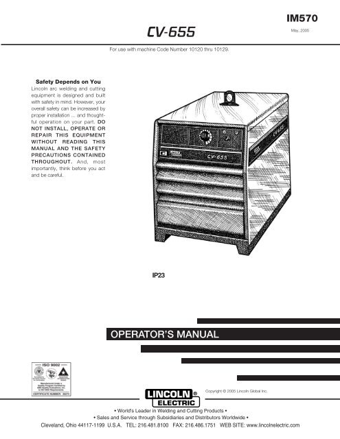
<strong>CV</strong>-<strong>655</strong><br />
IM570<br />
May, 2005<br />
For use with machine Code Number 10120 thru 10129.<br />
Safety Depends on You<br />
<strong>Lincoln</strong> arc welding and cutting<br />
equipment is designed and built<br />
with safety in mind. However, your<br />
overall safety can be increased by<br />
proper installation ... and thoughtful<br />
operation on your part. DO<br />
NOT INSTALL, OPERATE OR<br />
REPAIR THIS EQUIPMENT<br />
WITHOUT READING THIS<br />
MANUAL AND THE SAFETY<br />
PRECAUTIONS CONTAINED<br />
THROUGHOUT. And, most<br />
importantly, think before you act<br />
and be careful.<br />
IP23<br />
OPERATOR’S MANUAL<br />
Copyright © 2005 <strong>Lincoln</strong> Global Inc.<br />
• World's Leader in Welding and Cutting Products •<br />
• Sales and Service through Subsidiaries and Distributors Worldwide •<br />
Cleveland, Ohio 44117-1199 U.S.A. TEL: 216.481.8100 FAX: 216.486.1751 WEB SITE: www.lincolnelectric.com
i<br />
Diesel engine exhaust and some of its constituents<br />
are known to the State of California to cause cancer,<br />
birth defects, and other reproductive harm.<br />
The Above For Diesel Engines<br />
FOR ENGINE<br />
powered equipment.<br />
1.a. Turn the engine off before troubleshooting and maintenance<br />
work unless the maintenance work requires it to be running.<br />
____________________________________________________<br />
1.b. Operate engines in open, well-ventilated<br />
areas or vent the engine exhaust fumes<br />
outdoors.<br />
____________________________________________________<br />
1.c. Do not add the fuel near an open flame<br />
welding arc or when the engine is running.<br />
Stop the engine and allow it to cool before<br />
refueling to prevent spilled fuel from vaporizing<br />
on contact with hot engine parts and<br />
igniting. Do not spill fuel when filling tank. If<br />
fuel is spilled, wipe it up and do not start<br />
engine until fumes have been eliminated.<br />
____________________________________________________<br />
1.d. Keep all equipment safety guards, covers and devices in<br />
position and in good repair.Keep hands, hair, clothing and<br />
tools away from V-belts, gears, fans and all other moving<br />
parts when starting, operating or repairing equipment.<br />
____________________________________________________<br />
1.e. In some cases it may be necessary to remove safety<br />
guards to perform required maintenance. Remove<br />
guards only when necessary and replace them when the<br />
maintenance requiring their removal is complete.<br />
Always use the greatest care when working near moving<br />
parts.<br />
___________________________________________________<br />
1.f. Do not put your hands near the engine fan.<br />
Do not attempt to override the governor or<br />
idler by pushing on the throttle control rods<br />
while the engine is running.<br />
SAFETY<br />
WARNING<br />
CALIFORNIA PROPOSITION 65 WARNINGS<br />
The engine exhaust from this product contains<br />
chemicals known to the State of California to cause<br />
cancer, birth defects, or other reproductive harm.<br />
The Above For Gasoline Engines<br />
ARC WELDING CAN BE HAZARDOUS. PROTECT YOURSELF AND OTHERS FROM POSSIBLE SERIOUS INJURY OR DEATH.<br />
KEEP CHILDREN AWAY. PACEMAKER WEARERS SHOULD CONSULT WITH THEIR DOCTOR BEFORE OPERATING.<br />
Read and understand the following safety highlights. For additional safety information, it is strongly recommended that you<br />
purchase a copy of “Safety in Welding & Cutting - ANSI Standard Z49.1” from the American Welding Society, P.O. Box<br />
351040, Miami, Florida 33135 or CSA Standard W117.2-1974. A Free copy of “Arc Welding Safety” booklet E205 is available<br />
from the <strong>Lincoln</strong> <strong>Electric</strong> Company, 22801 St. Clair Avenue, Cleveland, Ohio 44117-1199.<br />
BE SURE THAT ALL INSTALLATION, OPERATION, MAINTENANCE AND REPAIR PROCEDURES ARE<br />
PERFORMED ONLY BY QUALIFIED INDIVIDUALS.<br />
1.h. To avoid scalding, do not remove the<br />
radiator pressure cap when the engine is<br />
hot.<br />
ELECTRIC AND<br />
MAGNETIC FIELDS<br />
may be dangerous<br />
2.a. <strong>Electric</strong> current flowing through any conductor causes<br />
localized <strong>Electric</strong> and Magnetic Fields (EMF). Welding<br />
current creates EMF fields around welding cables and<br />
welding machines<br />
2.b. EMF fields may interfere with some pacemakers, and<br />
welders having a pacemaker should consult their physician<br />
before welding.<br />
2.c. Exposure to EMF fields in welding may have other health<br />
effects which are now not known.<br />
2.d. All welders should use the following procedures in order to<br />
minimize exposure to EMF fields from the welding circuit:<br />
2.d.1. Route the electrode and work cables together - Secure<br />
them with tape when possible.<br />
2.d.2. Never coil the electrode lead around your body.<br />
2.d.3. Do not place your body between the electrode and<br />
work cables. If the electrode cable is on your right<br />
side, the work cable should also be on your right side.<br />
i<br />
___________________________________________________<br />
1.g. To prevent accidentally starting gasoline engines while<br />
turning the engine or welding generator during maintenance<br />
work, disconnect the spark plug wires, distributor cap or<br />
magneto wire as appropriate.<br />
Mar ‘95<br />
2.d.4. Connect the work cable to the workpiece as close as<br />
possible to the area being welded.<br />
2.d.5. Do not work next to welding power source.
ii<br />
SAFETY<br />
ii<br />
ELECTRIC SHOCK can<br />
kill.<br />
3.a. The electrode and work (or ground) circuits<br />
are electrically “hot” when the welder is on.<br />
Do not touch these “hot” parts with your bare<br />
skin or wet clothing. Wear dry, hole-free<br />
gloves to insulate hands.<br />
3.b. Insulate yourself from work and ground using dry insulation.<br />
Make certain the insulation is large enough to cover your full<br />
area of physical contact with work and ground.<br />
In addition to the normal safety precautions, if welding<br />
must be performed under electrically hazardous<br />
conditions (in damp locations or while wearing wet<br />
clothing; on metal structures such as floors, gratings or<br />
scaffolds; when in cramped positions such as sitting,<br />
kneeling or lying, if there is a high risk of unavoidable or<br />
accidental contact with the workpiece or ground) use<br />
the following equipment:<br />
• Semiautomatic DC Constant Voltage (Wire) Welder.<br />
• DC Manual (Stick) Welder.<br />
• AC Welder with Reduced Voltage Control.<br />
3.c. In semiautomatic or automatic wire welding, the electrode,<br />
electrode reel, welding head, nozzle or semiautomatic<br />
welding gun are also electrically “hot”.<br />
3.d. Always be sure the work cable makes a good electrical<br />
connection with the metal being welded. The connection<br />
should be as close as possible to the area being welded.<br />
3.e. Ground the work or metal to be welded to a good electrical<br />
(earth) ground.<br />
3.f.<br />
Maintain the electrode holder, work clamp, welding cable and<br />
welding machine in good, safe operating condition. Replace<br />
damaged insulation.<br />
3.g. Never dip the electrode in water for cooling.<br />
3.h. Never simultaneously touch electrically “hot” parts of<br />
electrode holders connected to two welders because voltage<br />
between the two can be the total of the open circuit voltage<br />
of both welders.<br />
3.i.<br />
When working above floor level, use a safety belt to protect<br />
yourself from a fall should you get a shock.<br />
3.j. Also see Items 6.c. and 8.<br />
ARC RAYS can burn.<br />
4.a. Use a shield with the proper filter and cover<br />
plates to protect your eyes from sparks and<br />
the rays of the arc when welding or observing<br />
open arc welding. Headshield and filter lens<br />
should conform to ANSI Z87. I standards.<br />
4.b. Use suitable clothing made from durable flame-resistant<br />
material to protect your skin and that of your helpers from<br />
the arc rays.<br />
4.c. Protect other nearby personnel with suitable, non-flammable<br />
screening and/or warn them not to watch the arc nor expose<br />
themselves to the arc rays or to hot spatter or metal.<br />
FUMES AND GASES<br />
can be dangerous.<br />
5.a. Welding may produce fumes and gases<br />
hazardous to health. Avoid breathing these<br />
fumes and gases.When welding, keep<br />
your head out of the fume. Use enough<br />
ventilation and/or exhaust at the arc to keep<br />
fumes and gases away from the breathing zone. When<br />
welding with electrodes which require special<br />
ventilation such as stainless or hard facing (see<br />
instructions on container or MSDS) or on lead or<br />
cadmium plated steel and other metals or coatings<br />
which produce highly toxic fumes, keep exposure as<br />
low as possible and below Threshold Limit Values (TLV)<br />
using local exhaust or mechanical ventilation. In<br />
confined spaces or in some circumstances, outdoors, a<br />
respirator may be required. Additional precautions are<br />
also required when welding on galvanized steel.<br />
5.b. Do not weld in locations near chlorinated hydrocarbon vapors<br />
coming from degreasing, cleaning or spraying operations.<br />
The heat and rays of the arc can react with solvent vapors to<br />
form phosgene, a highly toxic gas, and other irritating<br />
products.<br />
5.c. Shielding gases used for arc welding can displace air and<br />
cause injury or death. Always use enough ventilation,<br />
especially in confined areas, to insure breathing air is safe.<br />
5.d. Read and understand the manufacturer’s instructions for this<br />
equipment and the consumables to be used, including the<br />
material safety data sheet (MSDS) and follow your<br />
employer’s safety practices. MSDS forms are available from<br />
your welding distributor or from the manufacturer.<br />
5.e. Also see item 1.b.<br />
Mar ‘95
iii<br />
SAFETY<br />
iii<br />
WELDING SPARKS can<br />
cause fire or explosion.<br />
6.a. Remove fire hazards from the welding area.<br />
If this is not possible, cover them to prevent<br />
the welding sparks from starting a fire.<br />
Remember that welding sparks and hot<br />
materials from welding can easily go through small cracks<br />
and openings to adjacent areas. Avoid welding near<br />
hydraulic lines. Have a fire extinguisher readily available.<br />
6.b. Where compressed gases are to be used at the job site,<br />
special precautions should be used to prevent hazardous<br />
situations. Refer to “Safety in Welding and Cutting” (ANSI<br />
Standard Z49.1) and the operating information for the<br />
equipment being used.<br />
6.c. When not welding, make certain no part of the electrode<br />
circuit is touching the work or ground. Accidental contact<br />
can cause overheating and create a fire hazard.<br />
6.d. Do not heat, cut or weld tanks, drums or containers until the<br />
proper steps have been taken to insure that such procedures<br />
will not cause flammable or toxic vapors from substances<br />
inside. They can cause an explosion even though they have<br />
been “cleaned”. For information, purchase “Recommended<br />
Safe Practices for the Preparation for Welding and Cutting of<br />
Containers and Piping That Have Held Hazardous<br />
Substances”, AWS F4.1 from the American Welding Society<br />
(see address above).<br />
6.e. Vent hollow castings or containers before heating, cutting or<br />
welding. They may explode.<br />
6.f. Sparks and spatter are thrown from the welding arc. Wear oil<br />
free protective garments such as leather gloves, heavy shirt,<br />
cuffless trousers, high shoes and a cap over your hair. Wear<br />
ear plugs when welding out of position or in confined places.<br />
Always wear safety glasses with side shields when in a<br />
welding area.<br />
6.g. Connect the work cable to the work as close to the welding<br />
area as practical. Work cables connected to the building<br />
framework or other locations away from the welding area<br />
increase the possibility of the welding current passing<br />
through lifting chains, crane cables or other alternate circuits.<br />
This can create fire hazards or overheat lifting chains<br />
or cables until they fail.<br />
6.h. Also see item 1.c.<br />
CYLINDER may explode<br />
if damaged.<br />
7.a. Use only compressed gas cylinders<br />
containing the correct shielding gas for the<br />
process used and properly operating<br />
regulators designed for the gas and<br />
pressure used. All hoses, fittings, etc. should be suitable for<br />
the application and maintained in good condition.<br />
7.b. Always keep cylinders in an upright position securely<br />
chained to an undercarriage or fixed support.<br />
7.c. Cylinders should be located:<br />
• Away from areas where they may be struck or subjected to<br />
physical damage.<br />
• A safe distance from arc welding or cutting operations and<br />
any other source of heat, sparks, or flame.<br />
7.d. Never allow the electrode, electrode holder or any other<br />
electrically “hot” parts to touch a cylinder.<br />
7.e. Keep your head and face away from the cylinder valve outlet<br />
when opening the cylinder valve.<br />
7.f.<br />
Valve protection caps should always be in place and hand<br />
tight except when the cylinder is in use or connected for<br />
use.<br />
7.g. Read and follow the instructions on compressed gas<br />
cylinders, associated equipment, and CGA publication P-l,<br />
“Precautions for Safe Handling of Compressed Gases in<br />
Cylinders,” available from the Compressed Gas Association<br />
1235 Jefferson Davis Highway, Arlington, VA 22202.<br />
FOR ELECTRICALLY<br />
powered equipment.<br />
8.a. Turn off input power using the disconnect<br />
switch at the fuse box before working on<br />
the equipment.<br />
8.b. Install equipment in accordance with the U.S. National<br />
<strong>Electric</strong>al Code, all local codes and the manufacturer’s<br />
recommendations.<br />
8.c. Ground the equipment in accordance with the U.S. National<br />
<strong>Electric</strong>al Code and the manufacturer’s recommendations.<br />
Mar ‘95
iv<br />
SAFETY<br />
iv<br />
PRÉCAUTIONS DE SÛRETÉ<br />
Pour votre propre protection lire et observer toutes les instructions<br />
et les précautions de sûreté specifiques qui parraissent<br />
dans ce manuel aussi bien que les précautions de sûreté<br />
générales suivantes:<br />
Sûreté Pour Soudage A L’Arc<br />
1. Protegez-vous contre la secousse électrique:<br />
a. Les circuits à l’électrode et à la piéce sont sous tension<br />
quand la machine à souder est en marche. Eviter toujours<br />
tout contact entre les parties sous tension et la peau nue<br />
ou les vétements mouillés. Porter des gants secs et sans<br />
trous pour isoler les mains.<br />
b. Faire trés attention de bien s’isoler de la masse quand on<br />
soude dans des endroits humides, ou sur un plancher<br />
metallique ou des grilles metalliques, principalement dans<br />
les positions assis ou couché pour lesquelles une<br />
grande partie du corps peut être en contact avec la<br />
masse.<br />
c. Maintenir le porte-électrode, la pince de masse, le câble<br />
de soudage et la machine à souder en bon et sûr état<br />
defonctionnement.<br />
d.Ne jamais plonger le porte-électrode dans l’eau pour le<br />
refroidir.<br />
e. Ne jamais toucher simultanément les parties sous tension<br />
des porte-électrodes connectés à deux machines à souder<br />
parce que la tension entre les deux pinces peut être le<br />
total de la tension à vide des deux machines.<br />
f. Si on utilise la machine à souder comme une source de<br />
courant pour soudage semi-automatique, ces precautions<br />
pour le porte-électrode s’applicuent aussi au pistolet de<br />
soudage.<br />
5. Toujours porter des lunettes de sécurité dans la zone de<br />
soudage. Utiliser des lunettes avec écrans lateraux dans les<br />
zones où l’on pique le laitier.<br />
6. Eloigner les matériaux inflammables ou les recouvrir afin de<br />
prévenir tout risque d’incendie dû aux étincelles.<br />
7. Quand on ne soude pas, poser la pince à une endroit isolé de<br />
la masse. Un court-circuit accidental peut provoquer un<br />
échauffement et un risque d’incendie.<br />
8. S’assurer que la masse est connectée le plus prés possible<br />
de la zone de travail qu’il est pratique de le faire. Si on place<br />
la masse sur la charpente de la construction ou d’autres<br />
endroits éloignés de la zone de travail, on augmente le risque<br />
de voir passer le courant de soudage par les chaines de levage,<br />
câbles de grue, ou autres circuits. Cela peut provoquer<br />
des risques d’incendie ou d’echauffement des chaines et des<br />
câbles jusqu’à ce qu’ils se rompent.<br />
9. Assurer une ventilation suffisante dans la zone de soudage.<br />
Ceci est particuliérement important pour le soudage de tôles<br />
galvanisées plombées, ou cadmiées ou tout autre métal qui<br />
produit des fumeés toxiques.<br />
10. Ne pas souder en présence de vapeurs de chlore provenant<br />
d’opérations de dégraissage, nettoyage ou pistolage. La<br />
chaleur ou les rayons de l’arc peuvent réagir avec les<br />
vapeurs du solvant pour produire du phosgéne (gas fortement<br />
toxique) ou autres produits irritants.<br />
11. Pour obtenir de plus amples renseignements sur la sûreté,<br />
voir le code “Code for safety in welding and cutting” CSA<br />
Standard W 117.2-1974.<br />
2. Dans le cas de travail au dessus du niveau du sol, se protéger<br />
contre les chutes dans le cas ou on recoit un choc. Ne<br />
jamais enrouler le câble-électrode autour de n’importe quelle<br />
partie du corps.<br />
3. Un coup d’arc peut être plus sévère qu’un coup de soliel,<br />
donc:<br />
a. Utiliser un bon masque avec un verre filtrant approprié<br />
ainsi qu’un verre blanc afin de se protéger les yeux du<br />
rayonnement de l’arc et des projections quand on soude<br />
ou quand on regarde l’arc.<br />
b. Porter des vêtements convenables afin de protéger la<br />
peau de soudeur et des aides contre le rayonnement de<br />
l‘arc.<br />
c. Protéger l’autre personnel travaillant à proximité au<br />
soudage à l’aide d’écrans appropriés et non-inflammables.<br />
4. Des gouttes de laitier en fusion sont émises de l’arc de<br />
soudage. Se protéger avec des vêtements de protection<br />
libres de l’huile, tels que les gants en cuir, chemise épaisse,<br />
pantalons sans revers, et chaussures montantes.<br />
PRÉCAUTIONS DE SÛRETÉ POUR<br />
LES MACHINES À SOUDER À<br />
TRANSFORMATEUR ET À<br />
REDRESSEUR<br />
1. Relier à la terre le chassis du poste conformement au code<br />
de l’électricité et aux recommendations du fabricant. Le dispositif<br />
de montage ou la piece à souder doit être branché à<br />
une bonne mise à la terre.<br />
2. Autant que possible, I’installation et l’entretien du poste<br />
seront effectués par un électricien qualifié.<br />
3. Avant de faires des travaux à l’interieur de poste, la<br />
debrancher à l’interrupteur à la boite de fusibles.<br />
4. Garder tous les couvercles et dispositifs de sûreté à leur<br />
place.<br />
Mar. ‘93
v<br />
Thank You<br />
for selecting a QUALITY product by <strong>Lincoln</strong> <strong>Electric</strong>. We want you<br />
to take pride in operating this <strong>Lincoln</strong> <strong>Electric</strong> Company product<br />
••• as much pride as we have in bringing this product to you!<br />
v<br />
Please Examine Carton and Equipment For Damage Immediately<br />
When this equipment is shipped, title passes to the purchaser upon receipt by the carrier. Consequently, Claims<br />
for material damaged in shipment must be made by the purchaser against the transportation company at the<br />
time the shipment is received.<br />
Please record your equipment identification information below for future reference. This information can be<br />
found on your machine nameplate.<br />
Product _________________________________________________________________________________<br />
Model Number ___________________________________________________________________________<br />
Code Number or Date Code_________________________________________________________________<br />
Serial Number____________________________________________________________________________<br />
Date Purchased___________________________________________________________________________<br />
Where Purchased_________________________________________________________________________<br />
Whenever you request replacement parts or information on this equipment, always supply the information you<br />
have recorded above. The code number is especially important when identifying the correct replacement parts.<br />
Read this Operators Manual completely before attempting to use this equipment. Save this manual and keep it<br />
handy for quick reference. Pay particular attention to the safety instructions we have provided for your protection.<br />
The level of seriousness to be applied to each is explained below:<br />
WARNING<br />
On-Line Product Registration<br />
- Register your machine with <strong>Lincoln</strong> <strong>Electric</strong> either via fax or over the Internet.<br />
• For faxing: Complete the form on the back of the warranty statement included in the literature packet<br />
accompanying this machine and fax the form per the instructions printed on it.<br />
• For On-Line Registration: Go to our WEB SITE at www.lincolnelectric.com. Choose “Quick Links” and then<br />
“Product Registration”. Please complete the form and submit your registration.<br />
This statement appears where the information must be followed exactly to avoid serious personal injury or<br />
loss of life.<br />
CAUTION<br />
This statement appears where the information must be followed to avoid minor personal injury or damage to<br />
this equipment.
vi<br />
TABLE OF CONTENTS<br />
vi<br />
PAGE<br />
INSTALLATION . . . . . . . . . . . . . . . . . . . . . . . . . . . . . . . . . . . . . . . . . . . . . . . . . . . . . . . . . . . . . . . .SECTION A<br />
TECHNICAL SPECIFICATIONS – IDEALARC <strong>CV</strong>-<strong>655</strong> . . . . . . . . . . . . . . . . . . . . . . . . . . . . . . . . . . . .A-1<br />
GRAPHIC SYMBOLS THAT APPEAR ON RATING PLATE . . . . . . . . . . . . . . . . . . . . . . . . . . . . . . . .A-2<br />
SAFETY PRECAUTIONS . . . . . . . . . . . . . . . . . . . . . . . . . . . . . . . . . . . . . . . . . . . . . . . . . . . . . . . . . . .A-3<br />
SELECT SUITABLE LOCATION . . . . . . . . . . . . . . . . . . . . . . . . . . . . . . . . . . . . . . . . . . . . . . . . . . . . .A-3<br />
STACKING . . . . . . . . . . . . . . . . . . . . . . . . . . . . . . . . . . . . . . . . . . . . . . . . . . . . . . . . . . . . . . . . . . .A-3<br />
TILTING . . . . . . . . . . . . . . . . . . . . . . . . . . . . . . . . . . . . . . . . . . . . . . . . . . . . . . . . . . . . . . . . . . . . .A-3<br />
ELECTRICAL INPUT CONNECTIONS . . . . . . . . . . . . . . . . . . . . . . . . . . . . . . . . . . . . . . . . . . . . . . . . .A-3<br />
FUSE AND WIRE SIZES . . . . . . . . . . . . . . . . . . . . . . . . . . . . . . . . . . . . . . . . . . . . . . . . . . . . . . . .A-3<br />
GROUND CONNECTION . . . . . . . . . . . . . . . . . . . . . . . . . . . . . . . . . . . . . . . . . . . . . . . . . . . . . . .A-3<br />
INPUT POWER SUPPLY CONNECTIONS . . . . . . . . . . . . . . . . . . . . . . . . . . . . . . . . . . . . . . . . . .A-4<br />
RECONNECT PROCEDURE . . . . . . . . . . . . . . . . . . . . . . . . . . . . . . . . . . . . . . . . . . . . . . . . . . . . . . . .A-4<br />
OUTPUT CONNECTIONS . . . . . . . . . . . . . . . . . . . . . . . . . . . . . . . . . . . . . . . . . . . . . . . . . . . . . . . . . .A-5<br />
ELECTRODE AND WORK CABLES . . . . . . . . . . . . . . . . . . . . . . . . . . . . . . . . . . . . . . . . . . . . . . .A-5<br />
AUXILIARY POWER AND CONTROL CONNECTIONS . . . . . . . . . . . . . . . . . . . . . . . . . . . . . . . .A-6<br />
AUXILIARY POWER TABLE . . . . . . . . . . . . . . . . . . . . . . . . . . . . . . . . . . . . . . . . . . . . . . . . . . . .A-6<br />
115VAC DUPLEX RECEPTACLE . . . . . . . . . . . . . . . . . . . . . . . . . . . . . . . . . . . . . . . . . . . . . . . .A-6<br />
230V RECEPTACLE . . . . . . . . . . . . . . . . . . . . . . . . . . . . . . . . . . . . . . . . . . . . . . . . . . . . . . . . . .A-6<br />
14 PIN MS TYPE RECEPTACLE . . . . . . . . . . . . . . . . . . . . . . . . . . . . . . . . . . . . . . . . . . . . . . . .A-6<br />
TERMINAL STRIPS . . . . . . . . . . . . . . . . . . . . . . . . . . . . . . . . . . . . . . . . . . . . . . . . . . . . . . . . . .A-7<br />
OPERATION . . . . . . . . . . . . . . . . . . . . . . . . . . . . . . . . . . . . . . . . . . . . . . . . . . . . . . . . . . . . . . . . . .SECTION B<br />
SAFETY PRECAUTIONS . . . . . . . . . . . . . . . . . . . . . . . . . . . . . . . . . . . . . . . . . . . . . . . . . . . . . . . . . . .B-1<br />
GENERAL WARNINGS . . . . . . . . . . . . . . . . . . . . . . . . . . . . . . . . . . . . . . . . . . . . . . . . . . . . . . . . . . . .B-1<br />
GENERAL DESCRIPTION . . . . . . . . . . . . . . . . . . . . . . . . . . . . . . . . . . . . . . . . . . . . . . . . . . . . . . . . . .B-1<br />
RECOMMENDED PROCESSES AND EQUIPMENT . . . . . . . . . . . . . . . . . . . . . . . . . . . . . . . . . .B-1<br />
DESIGN FEATURES AND ADVANTAGES . . . . . . . . . . . . . . . . . . . . . . . . . . . . . . . . . . . . . . . . . .B-1<br />
WELDING CAPABILITY . . . . . . . . . . . . . . . . . . . . . . . . . . . . . . . . . . . . . . . . . . . . . . . . . . . . . . . . .B-2<br />
CONTROLS AND SETTINGS . . . . . . . . . . . . . . . . . . . . . . . . . . . . . . . . . . . . . . . . . . . . . . . . . . . . . . . .B-3<br />
AUXILIARY POWER . . . . . . . . . . . . . . . . . . . . . . . . . . . . . . . . . . . . . . . . . . . . . . . . . . . . . . . . . . . . . . .B-5<br />
THERMAL FAN CONTROL AND FAN MOTOR FUSE . . . . . . . . . . . . . . . . . . . . . . . . . . . . . . . . . . . .B-5<br />
OVERLOAD PROTECTION . . . . . . . . . . . . . . . . . . . . . . . . . . . . . . . . . . . . . . . . . . . . . . . . . . . . . . . . .B-5<br />
ACCESSORIES . . . . . . . . . . . . . . . . . . . . . . . . . . . . . . . . . . . . . . . . . . . . . . . . . . . . . . . . . . . . . . . .SECTION C<br />
FIELD INSTALLED OPTIONS . . . . . . . . . . . . . . . . . . . . . . . . . . . . . . . . . . . . . . . . . . . . . . . . . . . . . . .C-1<br />
MAINTENANCE . . . . . . . . . . . . . . . . . . . . . . . . . . . . . . . . . . . . . . . . . . . . . . . . . . . . . . . . . . . . . . . .SECTION D<br />
SAFETY PRECAUTIONS . . . . . . . . . . . . . . . . . . . . . . . . . . . . . . . . . . . . . . . . . . . . . . . . . . . . . . . . . . .D-1<br />
GENERAL MAINTENANCE . . . . . . . . . . . . . . . . . . . . . . . . . . . . . . . . . . . . . . . . . . . . . . . . . . . . . . . . .D-1<br />
TROUBLESHOOTING . . . . . . . . . . . . . . . . . . . . . . . . . . . . . . . . . . . . . . . . . . . . . . . . . . . . . . . . . . .SECTION E<br />
MACHINE TROUBLESHOOTING . . . . . . . . . . . . . . . . . . . . . . . . . . . . . . . . . . . . . . . . . . . . . . . . . . . .E-2<br />
P.C. BOARD TROUBLESHOOTING . . . . . . . . . . . . . . . . . . . . . . . . . . . . . . . . . . . . . . . . . . . . . . . . . .E-9<br />
DIAGRAMS . . . . . . . . . . . . . . . . . . . . . . . . . . . . . . . . . . . . . . . . . . . . . . . . . . . . . . . . . . . . . . . . . . . .SECTION F<br />
PARTS LISTS . . . . . . . . . . . . . . . . . . . . . . . . . . . . . . . . . . . . . . . . . . . . . . . . . . . . . . . . . . . . . . .P-284 SERIES
A-1 INSTALLATION<br />
TECHNICAL SPECIFICATIONS – <strong>CV</strong>-<strong>655</strong><br />
INPUT - THREE PHASE ONLY<br />
Standard<br />
Voltage<br />
Input Current at Rated Output<br />
100% Duty Cycle 60% Duty Cycle<br />
Code<br />
Number<br />
A-1<br />
230/460/60<br />
230/460/575/60<br />
208/416/60<br />
460/60<br />
575/60<br />
230/400/50/60*<br />
380/500/50/60*<br />
440/50/60<br />
200/400/50/60<br />
415/50/60<br />
INPUT<br />
VOLTAGE /<br />
208<br />
230<br />
416<br />
460<br />
575<br />
200<br />
230<br />
380<br />
400<br />
415<br />
440<br />
500<br />
Duty Cycle<br />
100% Duty Cycle<br />
NEMA Class I (100)*<br />
60% Duty Cycle<br />
Current Range<br />
HEIGHT<br />
27.5 in<br />
699 mm<br />
70-815<br />
94/47<br />
94/47/38<br />
104/52<br />
47<br />
38<br />
94/54<br />
56/43<br />
49<br />
107/54<br />
52<br />
RATED OUTPUT<br />
Amps<br />
650<br />
815<br />
OUTPUT<br />
Maximum Open Circuit Voltage<br />
48<br />
116/58<br />
116/58/47<br />
128/64<br />
58<br />
47<br />
116/67<br />
69/53<br />
60<br />
132/67<br />
64<br />
RECOMMENDED INPUT WIRE AND FUSE SIZES<br />
INPUT AMPERE TYPE 75°C<br />
RATING ON COPPER WIRE<br />
NAMEPLATE IN CONDUIT<br />
AWG(IEC-MM 2 ) SIZES<br />
40°C (104°F) Ambient<br />
60<br />
104<br />
1 (43)<br />
6 (14)<br />
60<br />
94<br />
2 (34)<br />
6 (14)<br />
60<br />
52<br />
6 (14)<br />
8 (8.4)<br />
60<br />
47<br />
6 (14)<br />
8 (8.4)<br />
60<br />
38<br />
8 (8.4)<br />
8 (8.4)<br />
50/60<br />
107<br />
1 (43)<br />
6 (14)<br />
50/60<br />
94<br />
2 (34)<br />
6 (14)<br />
50/60<br />
56<br />
6 (14)<br />
8 (8.4)<br />
50/60<br />
54<br />
6 (14)<br />
8 (8.4)<br />
50/60<br />
52<br />
6 (14)<br />
8 (8.4)<br />
50/60<br />
49<br />
6 (14)<br />
8 (8.4)<br />
50/60<br />
43<br />
8 (8.4)<br />
8 (8.4)<br />
HERTZ<br />
FREQUENCY<br />
PHYSICAL DIMENSIONS<br />
WIDTH<br />
22.2 in<br />
564 mm<br />
DEPTH<br />
38.0 in<br />
965 mm<br />
10120<br />
10121<br />
10122<br />
10123<br />
10124<br />
10125<br />
10126<br />
10127<br />
10128<br />
10129<br />
Volts at Rated Amperes<br />
44<br />
44<br />
Auxiliary Power<br />
See the OPERATION section<br />
for Auxiliary Power<br />
information by model<br />
TYPE 75°C<br />
GROUND WIRE<br />
IN CONDUIT<br />
AWG(IEC-MM 2 ) SIZES<br />
TYPE 75°C<br />
(SUPER LAG)<br />
OR BREAKER<br />
SIZE (AMPS) 1<br />
200 Amp<br />
175 Amp<br />
90 Amp<br />
90 Amp<br />
70 Amp<br />
200 Amp<br />
175 Amp<br />
100 Amp<br />
100 Amp<br />
90 Amp<br />
90 Amp<br />
80 Amp<br />
WEIGHT<br />
652 lbs.<br />
283 kg.<br />
* European models meet IEC974-1 standards.<br />
1 Also called “inverse time” or “thermal/magnetic” circuit breakers; circuit breakers which have a delay in tripping action that decreases as the magnitude of the current increases.<br />
<strong>CV</strong>-<strong>655</strong>
A-2<br />
INSTALLATION<br />
GRAPHIC SYMBOLS THAT APPEAR ON<br />
RATING PLATE (LOCATED ON CASE BACK)<br />
A-2<br />
3 Phase transformer with<br />
rectified DC output<br />
Constant Voltage Output<br />
Characteristics<br />
INPUT POWER<br />
GMAW<br />
THREE PHASE<br />
FCAW<br />
NEMA EW 1 (100%)<br />
Designates welder complies with<br />
National <strong>Electric</strong>al Manufacturers<br />
Association requirements EW 1<br />
Class I with 100% duty cycle at<br />
650Amps output. (Domestic,<br />
Canadian, and Export models)<br />
S<br />
Designates welder can be used<br />
in environments with increased<br />
hazard of electric shock.<br />
(European models)<br />
IEC 974-1<br />
Designates welder complies with<br />
International Electrotechnical<br />
Commission requirements 974-1.<br />
(European Models)<br />
R<br />
NRTL/C<br />
Designates welder complies with<br />
low voltage directive and with<br />
EMC directive. (European<br />
models)<br />
Designates welder complies with<br />
both Underwriters Laboratories<br />
(UL) standards and Canadian<br />
Standards Association (CSA)<br />
standards. (Canadian Model)<br />
R<br />
NRTL<br />
Designates welder complies with<br />
Underwriters Laboratories (UL)<br />
standards. (Domestic Models)<br />
<strong>CV</strong>-<strong>655</strong>
A-3<br />
INSTALLATION<br />
A-3<br />
Read entire installation section before starting<br />
installation.<br />
SAFETY PRECAUTIONS<br />
SELECT SUITABLE LOCATION<br />
Place the welder where clean cooling air can freely<br />
circulate in through the front louvers and out through<br />
the rear louvers. Dirt, dust or any foreign material that<br />
can be drawn into the welder should be kept at a<br />
minimum. Failure to observe these precautions can<br />
result in excessive operating temperatures and<br />
nuisance shut-downs.<br />
STACKING<br />
The <strong>CV</strong>-<strong>655</strong> may be stacked three-high provided the<br />
bottom machine is on a stable, hard, level surface. Be<br />
sure that the two pins in the roof fit into the slots in the<br />
base of the <strong>CV</strong>-<strong>655</strong> above it.<br />
TILTING<br />
WARNING<br />
ELECTRIC SHOCK can kill.<br />
• Only qualified personnel should<br />
perform this installation.<br />
• Turn the input power OFF at the disconnect<br />
switch or fuse box before working on<br />
this equipment.<br />
• Turn the Power switch on the <strong>CV</strong>-<strong>655</strong><br />
“OFF” before connecting or disconnecting<br />
output cables, wire feeder or remote<br />
connections, or other equipment.<br />
• Do not touch electrically hot parts.<br />
• Always connect the Idealarc <strong>CV</strong>-<strong>655</strong><br />
grounding terminal (located on the welder<br />
near the reconnect panel) to a good<br />
electrical earth ground.<br />
Do not place the machine on a surface that is inclined<br />
enough to create a risk of the machine falling over.<br />
ELECTRICAL<br />
INPUT CONNECTIONS<br />
Before installing the machine check that the input supply<br />
voltage, phase, and frequency are the same as the<br />
voltage, phase, and frequency as specified on the<br />
welder nameplate.<br />
INPUT POWER SUPPLY<br />
CABLE WITH BUSHING<br />
OR BOX CONNECTOR<br />
Input power supply entry is through the hole in the<br />
Case Back Assembly. See Figure A.1 for the location<br />
of the machine’s input cable entry opening, Input<br />
Contactor (CR1), and reconnect panel.<br />
FUSE AND WIRE SIZES<br />
Protect the input circuit with the super lag fuses or<br />
delay type circuit breakers listed on the Technical<br />
Specifications page of this manual for the machine<br />
being used. They are also called inverse time or thermal/magnetic<br />
circuit breakers.<br />
DO NOT use fuses or circuit breakers with a lower<br />
amp rating than recommended. This can result in<br />
“nuisance” tripping caused by inrush current even<br />
when machine is not being used for welding at high<br />
output currents.<br />
GROUND CONNECTION<br />
INPUT<br />
CONTACTOR (CR1)<br />
RECONNECT<br />
PANEL ASSEMBL Y<br />
FIGURE A.1 ELECTRICAL INPUT CONNECTIONS<br />
Ground the frame of the machine. A ground<br />
terminal marked with the symbol ( ) is located inside<br />
the case back of the machine near the input contactor.<br />
Access to the input box assembly is at the upper rear<br />
of the machine. See your local and national electrical<br />
codes for proper grounding methods. Use grounding<br />
wire sizes that meet local electrical codes or see the<br />
Technical Specifications page in this manual.<br />
Use input wire sizes that meet local electrical codes or<br />
see the Technical Specifications page in this manual.<br />
<strong>CV</strong>-<strong>655</strong>
A-4<br />
INPUT POWER SUPPLY CONNECTIONS<br />
A qualified electrician should connect the input power<br />
supply leads.<br />
INSTALLATION<br />
RECONNECT PROCEDURE<br />
WARNING<br />
<strong>Electric</strong> Shock Can Kill<br />
A-4<br />
1. Follow all national and local electrical codes.<br />
2. Use a three-phase line.<br />
3. Remove the input access door at upper rear of the<br />
machine.<br />
4. Follow input supply connection diagram located<br />
on the inside the door.<br />
5. Connect the three-phase AC power supply leads<br />
L1, L2, and L3 to the input contactor<br />
terminals in the input box assembly. See Figure<br />
A.1.<br />
• Disconnect input power before performing<br />
this procedure.<br />
------------------------------------------------------------------------<br />
Multiple voltage machines are shipped connected to<br />
the highest input voltage listed on the machine’s rating<br />
plate. Before installing the machine, check that the<br />
reconnect panel in the input box assembly is connected<br />
for the proper voltage.<br />
CAUTION<br />
Failure to follow these instructions can cause immediate<br />
failure of components within the machine.<br />
------------------------------------------------------------------------<br />
When powering welder from generator be sure to turn<br />
off welder first, before generator is shut down, in order<br />
to prevent damage to welder!<br />
To reconnect a multiple voltage machine to a different<br />
voltage, remove input power and follow the input connection<br />
diagram located on the inside of case back<br />
input access door.<br />
1. For dual voltage sample machine reconnect<br />
instructions, see Figure A.2.<br />
Do not operate with covers<br />
removed<br />
Disconnect input power before<br />
servicing<br />
Do not touch electrically live parts<br />
Only qualified persons should install,<br />
use or service this equipment<br />
DUAL VOLTAGE MACHINE<br />
INPUT SUPPLY CONNECTION DIAGRAM<br />
IMPORTANT: CHANGE LINK POSITIONS AND CONTROL TRANSFORMER CONNECTIONS.<br />
NOTE: MACHINES ARE SHIPPED FROM FACTORY CONNECTED FOR OVER 300 VOLTS<br />
CONNECTION FOR HIGHEST RATING PLATE VOLTAGE<br />
1. TURN OFF THE INPUT POWER USING THE DISCONNECT SWITCH AT THE FUSE BOX.<br />
L3<br />
INPUT<br />
L2<br />
LINES<br />
L1<br />
GND<br />
LINKS<br />
W<br />
CR1<br />
V<br />
CONTACTOR<br />
U<br />
H1<br />
H3<br />
CONTROL<br />
TRANSF.<br />
2. DISCONNECT AND INSULATE THE H2 LEAD TERMINAL WITH TAPE TO PROVIDE AT<br />
LEAST 600 VOLT INSULATION.<br />
3. CONNECT L1, L2 & L3 INPUT SUPPLY LINES AND H1 & H3 CONTROL TRANSFORMER<br />
LEADS TO THE INPUT SIDE OF CR1 CONTACTOR AS SHOWN.<br />
4. CONNECT TERMINAL MARKED TO GROUND PER LOCAL AND NATIONAL ELECTRIC<br />
CODES.<br />
5. MOUNT THE LINKS IN THE POSITIONS SHOWN; DOUBLE OR TRIPLE STACK THE LINKS<br />
H2<br />
IN THREE POSITIONS. LOOP THE FLEX LEAD IN THE POSITION SHOWN; POSITIONING<br />
THE LUGS TO MAINTAIN MAXIMUM CLEARANCE TO THE LINKS. INSTALL AND TIGHTEN<br />
ALL OF THE HEX NUTS.<br />
CONNECTION FOR LOWEST RATING PLATE VOLTAGE<br />
1. TURN OFF THE INPUT POWER USING THE DISCONNECT SWITCH AT THE FUSE BOX.<br />
L3<br />
INPUT<br />
L2<br />
LINES<br />
L1<br />
W<br />
CR1<br />
V<br />
CONTACTOR<br />
U<br />
GND<br />
H1<br />
H2<br />
LINKS<br />
CONTROL<br />
TRANSF.<br />
H3<br />
THE LINCOLN ELECTRIC CO., CLEVELAND OHIO U.S.A.<br />
2. DISCONNECT AND INSULATE THE H3 LEAD TERMINAL WITH TAPE TO PROVIDE AT<br />
LEAST 600 VOLT INSULATION.<br />
3. CONNECT L1, L2 & L3 INPUT SUPPLY LINES AND H1 & H2 CONTROL TRANSFORMER<br />
LEADS TO THE INPUT SIDE OF CR1 CONTACTOR AS SHOWN.<br />
4. CONNECT TERMINAL MARKED TO GROUND PER LOCAL AND NATIONAL ELECTRIC<br />
CODES.<br />
5. MOUNT THE LINKS IN THE POSITIONS SHOWN. CONNECT THE FLEX LEAD AS SHOWN;<br />
POSITIONING THE LUGS TO MAINTAIN MAXIMUM CLEARANCE TO THE LINKS.<br />
INSTALL AND TIGHTEN ALL OF THE HEX NUTS.<br />
D-UF<br />
M18225<br />
FIGURE A.2 Dual Voltage Machine Reconnection Procedure<br />
<strong>CV</strong>-<strong>655</strong>
A-5<br />
OUTPUT CONNECTIONS<br />
ELECTRODE AND WORK CABLES<br />
Use the shortest possible cable lengths. See Table<br />
A.1 for recommended cable sizes based on length.<br />
TABLE A.1<br />
Cable Sizes for Combined Lengths of Copper<br />
Electrode and Work Cable<br />
Cable Length<br />
ft. (m)<br />
0 (0) to 100 (30.4)<br />
100 (30.4) to 200 (60.8)<br />
200 (60.8) to 250 (76.2)<br />
The output terminals are located at the lower front of<br />
the welder behind a hinged door Refer to figure A.3.<br />
Route the welding cables through the slotted strain<br />
reliefs of the base to the welding terminals.<br />
For Positive Polarity:<br />
Parallel Cables<br />
2<br />
2<br />
2<br />
1. Connect the electrode cable to either the low inductance<br />
terminal (marked "<br />
") or the high<br />
inductance terminal (marked "<br />
"). See<br />
OPERATION section “Positive Output Terminals”<br />
for an explanation of the use of high or low inductance<br />
terminals.<br />
INSTALLATION<br />
Cable Size<br />
2/0 ( 70mm 2 )<br />
3/0 ( 95mm 2 )<br />
4/0 (120mm 2 )<br />
A-5<br />
2. Connect the work cable to the negative terminal<br />
marked “-”.<br />
3. Remove the terminal strip access cover panel on<br />
the lower case front. Refer to figure A.3 for the<br />
location.<br />
4. Work Sense lead #21 from the 14 Pin MS-receptacle<br />
must be connected to “-21”on the terminal strip.<br />
Note: This is how the <strong>CV</strong>-<strong>655</strong> is shipped from<br />
the factory.<br />
5. Replace the terminal strip access cover panel.<br />
For Negative Polarity:<br />
1. Connect the work cable to either the low inductance<br />
terminal (marked "<br />
") or the high inductance<br />
terminal (marked "<br />
"). See<br />
OPERATION section “Positive Output Terminals”<br />
for an explanation of the use of high or low inductance<br />
terminals.<br />
2. Connect the electrode cable to the negative terminal<br />
marked “-”.<br />
3. Remove the terminal strip access cover panel on<br />
the lower case front. Refer to figure A.3 for the<br />
location.<br />
4. Work Sense lead #21 from the 14 Pin MS-receptacle<br />
must be connected to “+21”on the terminal strip.<br />
5. Replace the terminal strip access cover panel.<br />
14 PIN MS RECEPTACLE<br />
NEGATIVE<br />
OUTPUT<br />
TERMINAL<br />
LOW INDUCTANCE<br />
POSITIVE OUTPUT<br />
TERMINAL<br />
HIGH INDUCTANCE<br />
POSITIVE OUTPUT<br />
TERMINAL<br />
TERMINAL STRIP<br />
COVER PANEL<br />
FIGURE A.3 Output Connections<br />
<strong>CV</strong>-<strong>655</strong>
A-6<br />
INSTALLATION<br />
A-6<br />
AUXILIARY POWER AND<br />
CONTROL CONNECTIONS<br />
Located at the lower front of the welder behind a<br />
hinged door is a 115VAC duplex receptacle for auxiliary<br />
power (Domestic and Canadian Models only) and<br />
a 14 Pin MS type receptacle for connection of auxiliary<br />
equipment such as wire feeders. Also, terminal<br />
strips with 115VAC and connections for auxiliary<br />
equipment are located behind the access panel on the<br />
lower case of the welder. A 220VAC receptacle for a<br />
water cooler (European and Export Models only) is<br />
located on the case back.<br />
AUXILIARY POWER TABLE<br />
Voltage and Circuit Breaker Ratings at Auxiliary Power<br />
Connections for Various Models<br />
Auxiliary Domestic Canadian European Export<br />
Power Models Model Models Models<br />
Connections (60Hz) (230/460/575V/60 Hz) (50/60 Hz) (50/60 Hz)<br />
14 PIN MS TYPE RECEPTACLE<br />
(For MS3106A-20-27PX Plug. L.E.C. Part #S12020-32)<br />
Refer to the figure A.4 for the available circuits in the<br />
14 pin receptacle.<br />
42 VAC is available at receptacle pins I and K.<br />
A 10 amp circuit breaker protects this circuit.<br />
115 VAC is available at receptacle pins A and J<br />
(Domestic, Canadian and Export Models). This circuit<br />
is protected by a circuit breaker (see Auxiliary Power<br />
Table). Note that the 42 VAC and 115 VAC circuits<br />
are electrically isolated from each other. However, on<br />
the European model one line of the 115VAC is connected<br />
to chassis ground.<br />
FIGURE A.4 FRONT VIEW OF 14-PIN CONNECTOR<br />
RECEPTACLE<br />
At Duplex 115V 20A 115V 15A No Duplex No Duplex<br />
Receptacle<br />
A=32<br />
K=42<br />
J=31<br />
Terminal strip 115V 20A 115V 15A 115V 15A 115V 15A<br />
terminals 31 & 32<br />
B=GND<br />
L<br />
I=41<br />
N<br />
MS-Receptacle 115V 20A 115V 15A Open Circuit 115V 15A<br />
pins A & J<br />
C=2<br />
H=21<br />
MS-Receptacle 42V 10A 42V 10A 42V 10A 42V 10A<br />
pins I & K<br />
D=4<br />
G=75<br />
At 220V No Receptacle No Receptacle 220V 2A 220V 2A<br />
Receptacle<br />
E=77<br />
M<br />
F=76<br />
115VAC DUPLEX RECEPTACLE (DOMESTIC AND<br />
CANADIAN MODELS ONLY)<br />
The 115VAC duplex receptacle is protected by a circuit<br />
breaker located below the receptacle (see<br />
Auxiliary Power Table). Receptacle is a NEMA 5-20R<br />
(protected by a 20 amp breaker) on Domestic Models<br />
and a NEMA 5-15R (protected by a 15 amp breaker)<br />
on Canadian Models.<br />
230VAC RECEPTACLE (EUROPEAN AND EXPORT<br />
MODELS ONLY)<br />
A Continental European receptacle is located on the<br />
rear panel for supplying 220VAC to a water cooler.<br />
The receptacle has a protective cover to prevent incidently<br />
contact and is a Schuko type. The circuit is protected<br />
by a 2 amp circuit breaker also located on the<br />
rear panel. This circuit is electrically isolated from all<br />
other circuits, but on the European Models one line is<br />
connected to chassis ground.<br />
PIN LEAD NO. FUNCTION<br />
A 32 115 VAC<br />
B GND Chassis Connection<br />
C 2 Trigger Circuit<br />
D 4 Trigger Circuit<br />
E 77 Output Control<br />
F 76 Output Control<br />
G 75 Output Control<br />
H 21 Work Sense Connection 2<br />
I 41 42 VAC<br />
J 31 115 VAC 1.<br />
K 42 42 VAC<br />
L --- ---<br />
M --- ---<br />
N --- ---<br />
1.<br />
115VAC circuit is not present on IEC 974-1 models.<br />
2.<br />
As shipped from the factory Lead #21 from the 14 Pin connector is<br />
connected to “-21” on the terminal strip. This is the configuration<br />
for positive welding. If welding negative polarity, connect lead #21<br />
to the “+21” connection point on the terminal strip.<br />
<strong>CV</strong>-<strong>655</strong>
A-7<br />
TERMINAL STRIPS<br />
INSTALLATION<br />
A-7<br />
Terminal strips are available behind the cover panel<br />
on the lower case front to connect wire feeder control<br />
cables that do not have a 14 Pin MS-type connector.<br />
Refer to figure A.3 for the location of this cover panel.<br />
These terminals supply the connections as shown in<br />
the following Terminal Strip charts. See Auxiliary<br />
Power Table for rating of circuit breaker in 115VAC<br />
circuit. Remove a plug button from the terminal strip<br />
cover and install an appropriate strain relief clamp for<br />
the cable being used. NOTE: There are two work<br />
sense lead connection points on the terminal strip.<br />
Connect both the work sense lead #21 from the 14 pin<br />
connector and #21 lead of the control cable to “-21”<br />
when welding positive polarity or to “+21” when welding<br />
negative polarity.<br />
TERMINAL STRIP 1 (T.S.1)<br />
Lead No.<br />
Function<br />
75 Output Control<br />
76 Output Control<br />
77 Output Control<br />
TERMINAL STRIP 2 (T.S.2)<br />
Lead No.<br />
Function<br />
+21 Work Connection<br />
-21 Work Connection 2<br />
41 42 VAC<br />
4 Trigger Circuit<br />
2 Trigger Circuit<br />
31 115 VAC 1<br />
32 115 VAC 1<br />
1.<br />
115VAC circuit is not present on IEC 974-1 models.<br />
2.<br />
As shipped from the factory Lead #21 from the 14 Pin connector is<br />
connected to “-21” on the terminal strip. This is the configuration<br />
for positive welding. If welding negative polarity, connect lead #21<br />
to the “+21” connection point on the terminal strip.<br />
<strong>CV</strong>-<strong>655</strong>
B-1<br />
SAFETY PRECAUTIONS<br />
OPERATION<br />
GENERAL DESCRIPTION<br />
B-1<br />
Read and understand this entire section before operating<br />
the machine.<br />
GENERAL WARNINGS<br />
WARNING<br />
ELECTRIC SHOCK<br />
can kill.<br />
• Do not touch electrically live parts<br />
or electrode with skin or wet<br />
clothing.<br />
• Insulate yourself from work and<br />
ground.<br />
• Always wear dry insulating<br />
gloves.<br />
FUMES AND GASES<br />
can be dangerous.<br />
• Keep your head out of fumes.<br />
• Use ventilation or exhaust to<br />
remove fumes from breathing<br />
zone.<br />
The <strong>CV</strong>-<strong>655</strong> is an energy efficient constant voltage DC power<br />
source that produces outstanding arc characteristics.<br />
Four models are available:<br />
Domestic - all 60 Hertz models except 230/460/575v.<br />
NEMA Class 1 rated<br />
Canadian - 230/460/575v 60 Hertz<br />
NEMA Class 1 rated<br />
European - 50/60 Hertz models rated for IEC 974-1<br />
Export - 50/60 Hertz models NEMA Class 1 rated<br />
RECOMMENDED PROCESSES AND<br />
EQUIPMENT<br />
The <strong>CV</strong>-<strong>655</strong> is designed for GMAW (MIG), FCAW,<br />
(except NR-203 family electrodes) and <strong>CV</strong> semi-automatic<br />
submerged arc welding processes (SAW), plus<br />
the capability of air carbon arc gouging (AAC) up to<br />
3/8” (10mm) diameter carbons. Limited <strong>CV</strong> automatic<br />
submerged arc welding with 5/64” and smaller wires.<br />
The <strong>CV</strong>-<strong>655</strong> is recommended for use with <strong>Lincoln</strong>’s<br />
DH-10 or LN-10 as well as the LN-7*, LN-7 GMA*, LN-<br />
742, LN-8*, LN-9*, LN-9 GMA*, LN-23P and LN-25<br />
semiautomatic wire feeders. It is also recommended<br />
for use with the NA-3, NA-5 and NA-5R automatic<br />
feeders, but “cold starting” for sub-arc cannot be used<br />
(it must be jumpered out).<br />
* The 14-pin MS receptacle on the European models<br />
does not provide 115 VAC for these feeders; 115 VAC<br />
must be obtained from terminal strip.<br />
WELDING SPARKS<br />
can cause fire or<br />
explosion<br />
• Keep flammable material away.<br />
• Do not weld on containers that<br />
have held combustibles.<br />
ARC RAYS<br />
can burn.<br />
• Wear eye, ear and body<br />
protection.<br />
Observe additional Safety Guidelines detailed<br />
throughout this manual.<br />
There are no provisions on the <strong>CV</strong>-<strong>655</strong> for paralleling.<br />
DESIGN FEATURES AND ADVANTAGES<br />
• Two inductance positions: operator can choose the optimum<br />
arc characteristics.<br />
• Power on/off switch with pilot light and thermostat tripped<br />
indicator light.<br />
• Full range output voltage control for easy operation.<br />
• Panel switches for remote or local output control, and output<br />
on or remote selection.<br />
• Hinged cover to protect output terminals and auxiliary connections.<br />
• 42 VAC, 10 amp auxiliary power available for the wire<br />
feeder; circuit breaker protected.<br />
<strong>CV</strong>-<strong>655</strong>
B-2<br />
DESIGN FEATURES AND ADVANTAGES<br />
(CONT’D)<br />
OPERATION<br />
B-2<br />
• 115 VAC, auxiliary power available for the wire<br />
feeder; circuit breaker protected. 20 amp breaker on<br />
Domestic model and 15 amp breaker on Canadian,<br />
European, and Export Models.<br />
• 115VAC duplex plug receptacle available on<br />
Domestic and Canadian Models. 20 amp breaker on<br />
Domestic Models and 15 amp breaker on Canadian<br />
Model.<br />
• Single MS-type (14-pin) connection for wire feeder.<br />
• Thermal Fan Control with electronic and thermostatic<br />
protection for current overload and excessive temperatures.<br />
• Optional Field Installed Digital or Analog<br />
Voltmeter/Ammeter kits are available.<br />
• 220 VAC receptacle on European and Export models<br />
for connecting to a water cooler. Protected by 2<br />
amp breaker.<br />
WELDING CAPABILITY<br />
The <strong>CV</strong>-<strong>655</strong> has the following Output and Duty Cycle<br />
based on operation for a 10 minute period:<br />
650 Amps, 44 Volts at 100%<br />
815 Amps, 44 Volts at 60%<br />
<strong>CV</strong>-<strong>655</strong>
B-3<br />
CONTROLS AND SETTINGS<br />
OPERATION<br />
B-3<br />
All operator controls and adjustments are located on the case front of the <strong>CV</strong>-<strong>655</strong>. Refer to Figures B.1, and B.2<br />
and corresponding explanations.<br />
7<br />
3<br />
2<br />
6<br />
1<br />
<strong>CV</strong>-<strong>655</strong><br />
4<br />
5<br />
1. INPUT POWER ON/OFF SWITCH - This toggle<br />
switch turns the machine on or off. Putting the<br />
switch in the ON position energizes the<br />
machine’s input contactor applying input power to<br />
the machine. Switching the switch to the<br />
OFF position de-energizes the input contactor.<br />
2. PILOT LIGHT - When the power switch is in the<br />
ON position the machine’s white pilot light will illuminate.<br />
If the input contactor de-energizes the<br />
machine in an overload situation the pilot will still<br />
illuminate. In this situation it will be necessary to<br />
reset the machine by switching the power switch to<br />
the OFF then ON position. (See Overload<br />
Protection Section)<br />
3. OUTPUT VOLTAGE CONTROL - This control<br />
provides continuous control of the machine’s output<br />
voltage from minimum to maximum (typical full pot<br />
range between 15 to 44 volts) as it is rotated clockwise.<br />
4. OUTPUT TERMINALS ON/REMOTE - When this<br />
switch is in the REMOTE position, the <strong>CV</strong>-<strong>655</strong>’s<br />
output terminals will be electrically “cold” until a<br />
remote device such as a wire feeder closes the #2<br />
and #4 circuit in the MS-receptacle or terminal strip.<br />
When this switch is in the ON position the<br />
FIGURE B.1 CONTROL PANEL CONTROLS<br />
<strong>CV</strong>-<strong>655</strong><br />
machine’s output terminals will be electrically energized<br />
all the time.<br />
5. LOCAL/REMOTE CONTROL SWITCH - When this<br />
switch is set to the LOCAL position, control of<br />
the output voltage is via the output voltage control<br />
on the <strong>CV</strong>-<strong>655</strong>’s control panel. When this switch is<br />
set to the REMOTE position, control is through<br />
a remote source such as a wire feeder via the #75,<br />
#76, and #77 leads in the MS-receptacle or terminal<br />
strip.<br />
6. THERMAL PROTECTION LIGHT - If the<br />
machine overheats due to lack of proper air flow<br />
through the machine or due to exceeding the<br />
machine’s duty cycle, thermostats will disable the<br />
welding output and this light will illuminate. Input<br />
power is still applied to the machine and the cooling<br />
fan will continue to run. When the machine cools<br />
the welding output will resume.<br />
7. OPTIONAL VOLTMETER & AMMETER - Digital<br />
or analog meter kits are available as field installed<br />
options. Refer to the Accessories Section of this<br />
manual.
B-4<br />
OPERATION<br />
B-4<br />
1 2<br />
3<br />
4<br />
6 5<br />
7<br />
FIGURE B.2 LOWER CASE FRONT CONTROLS & CONNECTIONS<br />
1. 115VAC DUPLEX RECEPTACLE (Domestic and<br />
Canadian Models) This receptacle provides up to<br />
20 amps of 115 VAC auxiliary power on the<br />
Domestic Models and up to 15 amps on the<br />
Canandian Model.<br />
2. 115VAC CIRCUIT BREAKER - This breaker<br />
protects the 115 VAC auxiliary circuits located in<br />
the duplex receptacle, terminal strip and MS- receptacle.<br />
Breaker is rated 20 amps on Domestic<br />
Models and 15 amps on all other models.<br />
3. 42VAC 10 AMP CIRCUIT BREAKER - This<br />
breaker protects the 42VAC auxiliary circuits located<br />
in the terminal strip and MS-receptacle.<br />
4. 14 PIN MS-RECEPTACLE - This connector provides<br />
easy connection for a wire feeder control<br />
cable. It provides connections for auxiliary power,<br />
output switching, remote output control, wire feeder<br />
voltmeter sense lead and ground. Refer to 14 Pin<br />
MS Type Receptacle in the Installation Section of<br />
this manual for information about the circuits made<br />
available at this receptacle.<br />
welding polarity and for proper welding cable size<br />
refer to Electrode and Work Cables in the<br />
Installation Section of this manual.<br />
7. POSITIVE OUTPUT TERMINALS - These output<br />
terminals are for connecting a welding cable to<br />
either the High Inductance<br />
or Low Inductance<br />
Terminal for desired arc characteristics. High<br />
Inductance is recommended for Stainless Steel<br />
welding. Low Inductance is recommended for Short<br />
Arc GMAW. For Spray Arc and other processes<br />
either may be used to provide the preferred starting<br />
and welding arc characteristics: High Inductance<br />
will provide a “softer” arc, but will not provide as<br />
“crisp” of an arc start as the Low Inductance. To<br />
change welding polarity and for proper welding<br />
cable size refer to Electrode and Work Cables in<br />
the Installation Section of this manual.<br />
5. TERMINAL STRIP COVER PANEL - Remove this<br />
panel to gain access to the circuits made available<br />
at the terminal strip. This terminal strip contains the<br />
same circuits as the 14 pin MS-receptacle. The<br />
cover also provides for installation of cable strain<br />
relief clamps.<br />
6. NEGATIVE OUTPUT TERMINAL - This output terminal<br />
is for connecting a welding cable. To change<br />
<strong>CV</strong>-<strong>655</strong>
B-5<br />
CASE BACK CONNECTIONS<br />
OPERATION<br />
THERMAL FAN CONTROL<br />
B-5<br />
220VAC AUXILIARY RECEPTACLE<br />
(European and Export Models)<br />
This receptacle provides up to 2 amps of 220VAC<br />
auxiliary power for a water cooler.<br />
220VAC 2 AMP CIRCUIT BREAKER<br />
(European and Export Models)<br />
This breaker protects the 220VAC auxiliary circuit<br />
located in the 220VAC receptacle.<br />
CAUTION<br />
When using a <strong>CV</strong>-<strong>655</strong> with wire feeders, there will be<br />
a small spark if the electrode contacts the work or<br />
ground with several seconds after releasing the trigger.<br />
When used with some wire feeders with the electrical<br />
trigger interlock in the ON position, the arc might<br />
restart if the electrode touches the work or ground<br />
during these several seconds.<br />
------------------------------------------------------------------------<br />
AUXILIARY POWER<br />
42 volt AC auxiliary power, as required for some wire<br />
feeders, is available through the wire feeder receptacle.<br />
A 10 amp circuit breaker protects the 42 volt circuit<br />
from overloads.<br />
<strong>CV</strong>-<strong>655</strong> machines can also supply 115 volt AC auxiliary<br />
power through the wire feeder receptacle. A 20<br />
amp circuit breaker on the Domestic model, and a 15<br />
amp on the Canadian and Export models protects the<br />
115 volt circuit from overloads. 115VAC is not available<br />
in the MS-receptacle on the European models.<br />
CAUTION<br />
Note that some types of equipment, especially pumps<br />
and large motors, have starting currents which are<br />
significantly higher than their running current. These<br />
higher starting currents may cause the circuit breaker<br />
to open. If this situation occurs, the user should refrain<br />
from using the <strong>CV</strong>-<strong>655</strong> auxiliary power for that equipment.<br />
___________________________________________<br />
The machine’s cooling fan remains off when the temperature<br />
of the rectifiers and windings inside the<br />
machine are below that requiring air flow cooling, as<br />
determined by electronic monitoring of several thermal<br />
sensors and the welding current of the machine. The<br />
fan may remain off until welding begins, but once the<br />
fan is activated, it will remain on for at least 5 minutes<br />
to assure proper cooling. This feature saves energy<br />
and also minimizes the amount of dirt and other air<br />
borne particles being drawn into the machine.<br />
OVERLOAD PROTECTION<br />
This welder has thermostatic protection from excessive<br />
duty cycles, overloads, loss of cooling, and high<br />
ambient temperatures. When the welder is subjected<br />
to an overload or loss of cooling, a thermostat will<br />
open. This condition will be indicated by the illumination<br />
of the yellow Thermostatic Protection Light on the<br />
case front (see Figure B.1).The fan will continue to run<br />
to cool the power source. No welding is possible until<br />
the machine is allowed to cool and the Thermostatic<br />
Protection Light goes out.<br />
The <strong>CV</strong>-<strong>655</strong> also has over-current protection. When<br />
the load exceeds a threshold current (about 900<br />
amps), overcurrent shut down will occur after a period<br />
of time that shortens as the current increases beyond<br />
this threshold. If the current reaches about 1000<br />
amps the output will be “clamped” at about 1000 amps<br />
and shut down will occur in about 5 seconds. When<br />
this overload shut down occurs the short circuit output<br />
of the machine drops to only about 20 amps, but the<br />
input contactor and input pilot light will remain on until<br />
reset by turning the power switch off, then back on<br />
with overload removed.<br />
FAN MOTOR FUSE (EUROPEAN MODEL)<br />
A 10 amp slow blow fuse protects the fan motor circuit.<br />
This fuse is located inside the <strong>CV</strong>-<strong>655</strong> mounted<br />
on the fan motor bracket.<br />
<strong>CV</strong>-<strong>655</strong>
C-1<br />
The <strong>CV</strong>-<strong>655</strong> can be used to power any of<br />
the following <strong>Lincoln</strong> Wire feeders:<br />
SEMI-AUTOMATIC WIRE FEEDERS<br />
ACCESSORIES<br />
C-1<br />
NOTE: A dirty air filter may cause the thermal protection<br />
of the <strong>CV</strong>-<strong>655</strong> to prematurely activate. Remove<br />
and blow out, or wash and dry, the filter every two<br />
months, or less if in extremely dirty conditions.<br />
Replace if necessary.<br />
• DH-10 • LN-9*<br />
• LN-10 • LN-9 GMA*<br />
• LN-7 GMA* • LN-23P<br />
• LN-742 • LN-25<br />
• LN-7 • LN-8*<br />
AUTOMATIC WIRE FEEDERS* #<br />
• NA-3 • NA-5R<br />
• NA-5<br />
Undercarriage (K817P, K842) - The <strong>CV</strong>-<strong>655</strong> is<br />
designed for use with the <strong>Lincoln</strong> K817P or K842<br />
Undercarriage. Complete installation instructions are<br />
included with each undercarriage. When any of the<br />
undercarriages are installed, the <strong>CV</strong>-<strong>655</strong> lift bail is no<br />
longer functional. Do not attempt to lift the machine<br />
with the undercarriage attached. The undercarriage is<br />
designed for moving the machine by hand only.<br />
Mechanized towing can lead to injury and /or damage<br />
to the <strong>CV</strong>-<strong>655</strong>.<br />
* European <strong>CV</strong>-<strong>655</strong> models only provide 115VAC for these feeders at the<br />
terminal strip (TS2)<br />
# “Cold starting for sub-arc cannot be used. (It must be jumpered out. See<br />
Auto Feeder manual)<br />
FIELD INSTALLED OPTIONS<br />
K1482-1 Digital Ammeter/Voltmeter Kit - Installs<br />
easily to the front control panel and provides digital<br />
display of actual welding voltage and amperage while<br />
welding. (Installation instructions are included with the<br />
kit).<br />
K1483-1 Analog Ammeter/Voltmeter Kit - Installs<br />
easily to the front control panel and provides analog<br />
display of actual welding voltage and amperage while<br />
welding. (Installation instructions are included with the<br />
kit).<br />
K1484-1 Dual Feeder Kit - This kit replaces the 14<br />
Pin MS-receptacle panel on the lower case front of the<br />
<strong>CV</strong>-<strong>655</strong>. It provides two 14 Pin MS-receptacles and a<br />
built in transfer circuit for connecting and operating<br />
two like-polarity wire feeders. European <strong>CV</strong>-<strong>655</strong> models<br />
can only use 42V feeders with this kit. (Installation<br />
instructions are included with the kit).<br />
K1485-1 Cable Hanger Bracket - Mounts over standard<br />
lift bale of the <strong>CV</strong>-<strong>655</strong> and provides a cable<br />
hanger on both sides of the power source, each side<br />
capable of holding up to 100 ft. of weld cable.<br />
(Installation instructions are included with the kit).<br />
K1486-1 Air Filter Kit - Removable metal filter easily<br />
slides in and out of a bracket which mounts to the<br />
front of the <strong>CV</strong>-<strong>655</strong>. Filter is designed to trap 80% of<br />
entering particles which are 5 microns, or larger, in<br />
size. (Installation instructions are included with the<br />
kit).<br />
REMOTE OUTPUT CONTROL<br />
(K775 or K857 WITH K864 ADAPTER)<br />
An optional “remote output control” is available. This is<br />
the same remote control that is used on other <strong>Lincoln</strong><br />
power sources (K775). The K775 consists of a control<br />
box with 28 ft (8.5m) of four conductor cable. This connects<br />
to terminals 75, 76, and 77 on the terminal strip<br />
and the case grounding screw so marked with the symbol<br />
on the machine. These terminals are located<br />
behind the cover panel on the lower connection panel of<br />
the <strong>CV</strong>-<strong>655</strong>. This control will give the same control as<br />
the output control on the machine.<br />
The K857 has a 6-pin MS-style connector. The K857<br />
requires a K864 adapter cable which connects to the<br />
14-pin connector on the <strong>CV</strong>-<strong>655</strong>.<br />
REMOTE CONTROL ADAPTER CABLE (K864)<br />
STRAIGHT PLUG (14 PIN)<br />
TO POWER SOURCE<br />
CABLE RECEPTACLE (6 SOCKET)<br />
TO: K857 REMOTE CONTROL<br />
CABLE RECEPTACLE (14 SOCKET)<br />
TO: LN-7 WIRE FEEDERS<br />
A “V” cable 12” (.30m) long to connect a K857<br />
Remote Control (6 pin connector) with a wire-feeder<br />
(14-pin connector) and the machine (14-pin connector).<br />
If a remote control is used alone the wire-feeder<br />
connection is then not used.<br />
<strong>CV</strong>-<strong>655</strong>
D-1<br />
SAFETY PRECAUTIONS<br />
WARNING<br />
ELECTRIC SHOCK can kill.<br />
MAINTENANCE<br />
D-1<br />
• Only qualified personnel should<br />
perform this maintenance.<br />
• Turn the input power OFF at the<br />
disconnect switch or fuse box<br />
before working on this<br />
equipment.<br />
• Do not touch electrically hot<br />
parts.<br />
GENERAL MAINTENANCE<br />
1. The fan motor has sealed bearings which require<br />
no service.<br />
2. In extremely dusty locations, dirt may restrict the<br />
cooling air causing the welder to run hot with premature<br />
tripping of thermal protection. Blow out the<br />
welder with low pressure air at regular intervals to<br />
eliminate excessive dirt and dust build-up on internal<br />
parts.<br />
3. Periodically check the welding cables. Inspect for<br />
any slits or punctures. Also make sure that all connections<br />
are tight.<br />
<strong>CV</strong>-<strong>655</strong>
E-1<br />
TROUBLESHOOTING<br />
E-1<br />
HOW TO USE TROUBLESHOOTING GUIDE<br />
This Troubleshooting Guide is provided to<br />
help you locate and remedy possible problems<br />
with machine setup or operation.<br />
Simply follow the three-step procedure<br />
listed below.<br />
Step 1. LOCATE PROBLEM (SYMPTOM).<br />
Look under the column labeled “PROBLEM<br />
(SYMPTOMS)”. This column describes possible<br />
symptoms that the machine may<br />
exhibit. Find the listing that best describes<br />
the symptom that the machine is exhibiting.<br />
WARNING<br />
Service and Repair should only be performed by <strong>Lincoln</strong> <strong>Electric</strong> Factory Trained Personnel.<br />
Unauthorized repairs performed on this equipment may result in danger to the technician and<br />
machine operator and will invalidate your factory warranty. For your safety and to avoid<br />
<strong>Electric</strong>al Shock, please observe all safety notes and precautions detailed throughout this<br />
manual.<br />
__________________________________________________________________________<br />
Step 2. PERFORM EXTERNAL TESTS.<br />
The second column labeled “POSSIBLE<br />
AREAS OF MISADJUSTMENT(S)” lists the<br />
obvious external possibilities that may contribute<br />
to the machine symptom. Perform<br />
these tests/checks in the order listed. In<br />
general, these tests can be conducted without<br />
removing the case wrap-around cover.<br />
Step 3. PERFORM COMPONENT TESTS.<br />
If you have exhausted all of the recommended<br />
tests in Step 2, Consult your Local<br />
Authorized Field Service Facility.<br />
CAUTION<br />
If for any reason you do not understand the test procedures or are unable to perform<br />
the tests/repairs safely, contact your LOCAL AUTHORIZED LINCOLN ELECTRIC<br />
FIELD SERVICE FACILITY for assistance before you proceed.<br />
_____________________________________________________________________<br />
<strong>CV</strong>-<strong>655</strong>
E-2<br />
TROUBLESHOOTING<br />
E-2<br />
PROBLEMS<br />
(SYMPTOMS)<br />
Input contactor (CR1) chatters.<br />
Observe all Safety Guidelines detailed througout this manual<br />
POSSIBLE<br />
CAUSE<br />
PROBLEMS<br />
1. Faulty input contactor (CR1).<br />
2. Low line voltage.<br />
RECOMMENDED<br />
COURSE OF ACTION<br />
Machine input contactor does not<br />
operate.<br />
1. Make sure the proper threephase<br />
input power is applied to<br />
the <strong>CV</strong><strong>655</strong> machine.<br />
2. The input contactor may be<br />
faulty.<br />
3. The power switch (SW1) may be<br />
faulty.<br />
4. The pilot transformer may be<br />
faulty.<br />
Machine input contactor operates,<br />
but no output when trying to weld.<br />
1. Electrode or work cables may be<br />
loose or broken.<br />
2. Firing P.C. board is not connected<br />
or is faulty. See PC board LED<br />
information.<br />
If all recommended possible areas<br />
of misadjustments have been<br />
checked and the problem persists,<br />
contact your local <strong>Lincoln</strong><br />
Authorized Field Service Facility.<br />
4. Trigger circuit may not be working.<br />
Place Output Terminals Switch to<br />
the ON position, or place a jumper<br />
wire across #2 and #4 on the terminal<br />
strip. LED 6 on the control<br />
PC board should go ON. If it does<br />
not light check for opens in the #2<br />
and #4 circuit. See wiring diagram.<br />
If LED 6 does light the control<br />
board may be faulty.<br />
5. If the thermal protection light is<br />
ON the machine is overheated.<br />
The choke or secondary thermostats<br />
may be open. Make<br />
sure the fan is operating and<br />
remove the cause of the overheating<br />
problem. See PC board<br />
LED information.<br />
CAUTION<br />
If for any reason you do not understand the test procedures or are unable to perform the tests/repairs safely, contact your<br />
Local <strong>Lincoln</strong> Authorized Field Service Facility for technical troubleshooting assistance before you proceed.<br />
<strong>CV</strong>-<strong>655</strong>
E-3<br />
TROUBLESHOOTING<br />
E-3<br />
PROBLEMS<br />
(SYMPTOMS)<br />
Machine has maximum output, but<br />
no control.<br />
Observe all Safety Guidelines detailed througout this manual<br />
PPOSSIBLE<br />
CAUSE<br />
PROBLEMS<br />
1. Check the Local/Remote output<br />
switch (SW3) and associated<br />
leads. See wiring diagram.<br />
2. Make sure the remote control<br />
leads #75, #76 and /or #77 are<br />
NOT grounded to the negative<br />
welding output.<br />
3. The output control potentiometer<br />
may be faulty.<br />
4. The control board or control<br />
board transformer (T3) may be<br />
faulty.<br />
RECOMMENDED<br />
COURSE OF ACTION<br />
Machine has minimum output and no<br />
control.<br />
Machine does not have maximum<br />
output.<br />
1. The remote control leads #75,<br />
#76 and/or #77 may be grounded<br />
to the positive welding output.<br />
1. Make sure the correct threephase<br />
input is applied to the<br />
<strong>CV</strong><strong>655</strong> machine.<br />
If all recommended possible areas<br />
of misadjustments have been<br />
checked and the problem persists,<br />
contact your local <strong>Lincoln</strong><br />
Authorized Field Service Facility.<br />
2. The output control potentiometer<br />
may be faulty.<br />
3. The Local/Remote switch (SW3)<br />
may be faulty.<br />
4. The control or firing boards may<br />
be faulty. See PC board LED<br />
information.<br />
Poor arc striking with semiautomatic<br />
or automatic wire feeders.<br />
1. Make sure the welding cables<br />
and connections are secure.<br />
2. Check for correct welding porcedures.<br />
CAUTION<br />
If for any reason you do not understand the test procedures or are unable to perform the tests/repairs safely, contact your<br />
Local <strong>Lincoln</strong> Authorized Field Service Facility for technical troubleshooting assistance before you proceed.<br />
<strong>CV</strong>-<strong>655</strong>
E-4<br />
TROUBLESHOOTING<br />
E-4<br />
PROBLEMS<br />
(SYMPTOMS)<br />
Variable or sluggish welding arc.<br />
Observe all Safety Guidelines detailed througout this manual<br />
PPOSSIBLE<br />
CAUSE<br />
PROBLEMS<br />
1. Make sure the welding cables are<br />
sized correctly and the connections<br />
are tight.<br />
2. Make sure the welding procedures<br />
are correct.<br />
RECOMMENDED<br />
COURSE OF ACTION<br />
Machine will not shut off.<br />
1. The input power switch (SW1)<br />
may be faulty.<br />
2. The input contactor (CR1) may<br />
be faulty.<br />
Output Control Pot not functioning in<br />
“Local” control.<br />
1. Check the Local/Remote control<br />
switch and associated leads.<br />
See wiring diagram.<br />
2. The machine output control<br />
potentiometer may be faulty.<br />
Also check associated leads.<br />
See wiring diagram.<br />
If all recommended possible areas<br />
of misadjustments have been<br />
checked and the problem persists,<br />
contact your local <strong>Lincoln</strong><br />
Authorized Field Service Facility.<br />
No output control in “Remote” control.<br />
1. Output Control Switch in wrong<br />
position.<br />
2. Faulty Output Control Switch.<br />
3. Faulty Remote Control Pot.<br />
4. Leads or connections open in control<br />
circuit. (#75, #76, #77)<br />
CAUTION<br />
If for any reason you do not understand the test procedures or are unable to perform the tests/repairs safely, contact your<br />
Local <strong>Lincoln</strong> Authorized Field Service Facility for technical troubleshooting assistance before you proceed.<br />
<strong>CV</strong>-<strong>655</strong>
E-5<br />
TROUBLESHOOTING<br />
E-5<br />
PROBLEMS<br />
(SYMPTOMS)<br />
Machine will not weld. O<strong>CV</strong> is less<br />
than 1 volt.<br />
Observe all Safety Guidelines detailed througout this manual<br />
POSSIBLE<br />
CAUSE<br />
PROBLEMS<br />
1. The machine may be in a overload<br />
condition. Remove the short<br />
circuit or excessive load on the<br />
output terminals.<br />
2. See the PC board LED information.<br />
RECOMMENDED<br />
COURSE OF ACTION<br />
The wire feeder will not come on.<br />
1. Either the 42VAC or the 115VAC<br />
circuit breakers may be tripped.<br />
Reset if necessary.<br />
2. Check for the presence of the<br />
required voltage to operate the<br />
wire feeder.<br />
3. The control cable or wire feeder<br />
may be faulty.<br />
Poor starting.<br />
1. The capacitor discharge resistor<br />
(R2) may be faulty. See wiring<br />
diagram.<br />
2. The control board may be faulty.<br />
See PC board LED information.<br />
If all recommended possible areas<br />
of misadjustments have been<br />
checked and the problem persists,<br />
contact your local <strong>Lincoln</strong><br />
Authorized Field Service Facility.<br />
CAUTION<br />
If for any reason you do not understand the test procedures or are unable to perform the tests/repairs safely, contact your<br />
Local <strong>Lincoln</strong> Authorized Field Service Facility for technical troubleshooting assistance before you proceed.<br />
<strong>CV</strong>-<strong>655</strong>
E-6<br />
TROUBLESHOOTING<br />
E-6<br />
PROBLEMS<br />
(SYMPTOMS)<br />
Poor arc characteristics.<br />
Observe all Safety Guidelines detailed througout this manual<br />
POSSIBLE<br />
CAUSE<br />
PROBLEMS<br />
1. The positive welding cable may be<br />
connected to the wrong inductance<br />
tap.<br />
2. The output capacitors may be<br />
faulty. Warning:The liquid electrolyte<br />
in the these capacitors is<br />
toxic. Avoid contact with any portion<br />
of your body. Clean up vented<br />
electrolyte using rubber gloves<br />
and a water dampaned cloth.<br />
Any electrolyte which gets on the<br />
skin, clean with soap and water.<br />
3. The control board may be faulty.<br />
See PC board LED information.<br />
RECOMMENDED<br />
COURSE OF ACTION<br />
115VAC receptacle not working.<br />
(60HZ machines only)<br />
1. Check the 115VAC circuit breaker.<br />
Reset if necessary. Make<br />
sure the load on the receptacle<br />
does not exceed the rating of the<br />
115VAC breaker (either 15A or<br />
20A). See wiring diagram.<br />
If all recommended possible areas<br />
of misadjustments have been<br />
checked and the problem persists,<br />
contact your local <strong>Lincoln</strong><br />
Authorized Field Service Facility.<br />
CAUTION<br />
If for any reason you do not understand the test procedures or are unable to perform the tests/repairs safely, contact your<br />
Local <strong>Lincoln</strong> Authorized Field Service Facility for technical troubleshooting assistance before you proceed.<br />
<strong>CV</strong>-<strong>655</strong>
E-7<br />
TROUBLESHOOTING<br />
E-7<br />
PROBLEMS<br />
(SYMPTOMS)<br />
Thermal Protection Light comes ON<br />
and fan does not run.<br />
Observe all Safety Guidelines detailed througout this manual<br />
POSSIBLE<br />
CAUSE<br />
PROBLEMS<br />
1. Check for obstructions that could<br />
prevent the fan from turning.<br />
RECOMMENDED<br />
COURSE OF ACTION<br />
NOTE: Fan is thermal controlled and<br />
does not continuously run when<br />
machine is powered up.<br />
2. Check the fan control ciruit. See<br />
wiring diagram.<br />
3. The fan motor may be faulty.<br />
4. The Thermal Fan/Snubber PC<br />
board may be faulty. See PC<br />
board LED information.<br />
Fan runs continuously.<br />
1. The Thermal Fan Thermistor may<br />
be faulty. See wiring diagram.<br />
2. The Thermal Fan/Snubber PC<br />
board may be faulty. See PC<br />
board LED information.<br />
One or both Digital Meters not lighting.<br />
Digital Voltmeter not working properly<br />
or erratic display.<br />
1. The meters may not be receiving<br />
the voltages from the auxiliary<br />
transformer. Check plug P13.<br />
See wiring diagram.<br />
2. The Digital meter PC board may<br />
be faulty.<br />
1. Meter may not be receiving auxiliary<br />
or sensing voltages. Make<br />
sure plug P12 & P13 are securely<br />
plugged into the Digital meter PC<br />
board and also plug P3 is securely<br />
plugged into the control board.<br />
2. The may be an open in the voltage<br />
feedback circuit. See wiring<br />
diagram.<br />
3. The Digital meter PC board may<br />
be faulty.<br />
If all recommended possible areas<br />
of misadjustments have been<br />
checked and the problem persists,<br />
contact your local <strong>Lincoln</strong><br />
Authorized Field Service Facility.<br />
CAUTION<br />
If for any reason you do not understand the test procedures or are unable to perform the tests/repairs safely, contact your<br />
Local <strong>Lincoln</strong> Authorized Field Service Facility for technical troubleshooting assistance before you proceed.<br />
<strong>CV</strong>-<strong>655</strong>
E-8<br />
TROUBLESHOOTING<br />
E-8<br />
PROBLEMS<br />
(SYMPTOMS)<br />
Digital Ammeter not working properly<br />
or erratic display.<br />
Observe all Safety Guidelines detailed througout this manual<br />
POSSIBLE<br />
CAUSE<br />
PROBLEMS<br />
1. The meter PC board may not be<br />
receiving the auxiliary or sensing<br />
voltages. Check plug P3 and<br />
plugs P12 & P13. See wiring<br />
diagram.<br />
2. The current feedback circuit may<br />
be faulty. From the shunt to the<br />
control board. See wiring diagram.<br />
3. The Digital meter PC board may<br />
be faulty.<br />
RECOMMENDED<br />
COURSE OF ACTION<br />
Analog Meters not reading, or not<br />
reading correctly.<br />
1. The meters may not be receiving<br />
voltage or current feedback signals.<br />
Make sure plug P3 is<br />
securely plugged in the control<br />
board and plug J14 (in-line connector)<br />
is securely seated in the<br />
plug assembly from the control<br />
board.<br />
2. Check the current feedback and<br />
voltage feedback circuits. See<br />
wiring diagram.<br />
3. The meter(s) may be defective.<br />
If all recommended possible areas<br />
of misadjustments have been<br />
checked and the problem persists,<br />
contact your local <strong>Lincoln</strong><br />
Authorized Field Service Facility.<br />
220VAC receptacle not working.<br />
(50/60 HZ machines only)<br />
1. Check the circuit breaker. Reset<br />
if necessary.<br />
2. Check for broken or loose connections<br />
in the 220VAC circuit.<br />
See wiring diagram.<br />
CAUTION<br />
If for any reason you do not understand the test procedures or are unable to perform the tests/repairs safely, contact your<br />
Local <strong>Lincoln</strong> Authorized Field Service Facility for technical troubleshooting assistance before you proceed.<br />
<strong>CV</strong>-<strong>655</strong>
E-9<br />
TROUBLESHOOTING<br />
Observe all Safety Guidelines detailed througout this manual<br />
PC BOARD TROUBLESHOOTING GUIDE - FIRING PRINTED CIRCUIT BOARD<br />
1. All 10 LED’s must be ON when the POWER SOURCE is turned ON and the wire feeder’s trigger is closed, or<br />
a jumper is placed between 2 & 4, or the “OUTPUT TERMINALS SWITCH” is in the ON position.<br />
2. LED’s 7, 8, and 9 indicate AC power being supplied to the P.C. board from auxiliary windings (T1). If a light is<br />
not on, turn the machine off and unplug P5 from the firing board. Turn the machine back on and check the following<br />
voltages:<br />
Light that was off Check AC voltage between Voltage should be approximately<br />
7 P5 pins 15 & 16 (wires 203,204) 32VAC<br />
8 P5 pins 7 & 8 (wires 205,206) 32VAC<br />
9 P5 pins 5 & 6 (wires 207,208) 32VAC<br />
3. If all voltages are present, turn power off, and plug P5 back into J5. Turn power back on. If LED’s are still out,<br />
replace firing Printed Circuit Board (PCB).<br />
4. If voltages were not present then check the wiring back to the auxiliary windings for a possible open.<br />
5. LED 10 senses when 2 and 4 are closed. Close 2 & 4, LED 10 should be “on”. Open 2 & 4, LED 10 should be<br />
“off”.<br />
6. LED’s 1 through 6 indicate gate signals are being sent to the main SCR’s 1 through 6 respectively If LED5 is<br />
on (CONTROL BOARD), along with LED7, 8, and 9 on firing (PCB), and LED’s 1 through 6 are not on, check<br />
to make sure lead 231 between control board and firing board is not broken.<br />
7. If any one of LED 1 through 6 are not on and LED’s 7,8, and 9 are on, replace the firing (PCB) .<br />
E-9<br />
PC BOARD TROUBLESHOOTING GUIDE - CONTROL PRINTED CIRCUIT BOARD<br />
1. LED1 indicates AC input voltage necessary to generate the DC supply voltages is present. These voltages<br />
power the control board circuitry. LED2 indicates the -10V supply is OK. LED3 indicates the +16V supply is<br />
OK. If LED1, 2, or 3 are not ON when machine POWER IS ON, Replace Printed Circuit Board.<br />
2. LED4 should not be on. If this LED comes on while welding, the machine will phase back to about 10 amps<br />
and stay there. This was do to either a short across output, or a current draw of about 1000A. Remove short<br />
or reduce output current. If no short or 1000 amp load exists, replace Control Printed Circuit Board.<br />
3. LED5 indicates control voltage is present. With trigger circuit OPEN and CONTROL POT set to minimum,<br />
LED5 should be very bright. Closing trigger circuit and Turning CONTROL POT towards maximum, LED5<br />
should dim and then go out. Replace Printed Circuit Board if LED5 does not go ON.<br />
4. LED6 indicates trigger condition. LED6 ON indicates trigger is CLOSED. LED6 OFF indicates trigger is OPEN.<br />
If LED6 does not come ON, look for open connections in the 2 & 4 circuit.<br />
5. LED7 indicates welder output voltage is being sensed on the control board. When turning the Control Pot<br />
towards maximum, LED7 should glow brighter. If LED7 does not light, made sure lead 222 from the negative<br />
output lead is connected to J1 PIN 14.<br />
6. LED8 indicates a fault condition. When LED8 is ON the machine is phased back to 10 amps and will stay<br />
there until the POWER SWITCH is turned OFF then back ON. This fault is do to a short across welder’s output,<br />
or 1000 amp current draw. If no short or 1000 amp load exists, replace Control Printed Circuit Board.<br />
7. LED’s 9 & 11 should be OFF on <strong>CV</strong>-<strong>655</strong> machines.<br />
8. LED10 should be ON when machine power is ON. If not replace Control (PCB).<br />
CAUTION<br />
If for any reason you do not understand the test procedures or are unable to perform the tests/repairs safely, contact your<br />
Local <strong>Lincoln</strong> Authorized Field Service Facility for technical troubleshooting assistance before you proceed.<br />
<strong>CV</strong>-<strong>655</strong>
E-10<br />
TROUBLESHOOTING<br />
Observe all Safety Guidelines detailed througout this manual<br />
E-10<br />
PC BOARD TROUBLESHOOTING GUIDE - THERMAL FAN/ SNUBBER PRINTED<br />
CIRCUIT BOARD<br />
NOTE: Fan will run for minimum of 5 minutes once fan turns on.<br />
1. LED1 when ON indicates fan should be running. If ON and machine is cold, replace Printed Circuit Board.<br />
2. LED2 when ON indicates welding current greater than 50 amps. If ON and not drawing more than 40 amps,<br />
replace Printed Circuit Board.<br />
3. LED3 when ON indicates Main SCR’S need cooling and turns fan ON. If ON and machine is cold, replace<br />
Printed Circuit Board.<br />
4. LED4 when ON indicates an open Thermal Fan Thermistor, or open connection to Printed Circuit Board. Fan<br />
will run constantly. Check Thermal Fan Thermistor for an open. If open replace. If not open Replace Printed<br />
Circuit Board.<br />
5. LED5 when ON indicates an open thermostat. Thermal Protection light should also be ON. If Thermal<br />
Protection light is not ON, and LED5 is ON, replace Printed Circuit Board.<br />
6. LED6 when ON indicates fan should be running. LED6 will be ON whenever LED’s 2, 3 4 or 5 is ON. If LED’s<br />
2, 3, 4, or 5 are not ON when LED6 is ON, replacePrinted Circuit Board.<br />
CAUTION<br />
If for any reason you do not understand the test procedures or are unable to perform the tests/repairs safely, contact your<br />
Local <strong>Lincoln</strong> Authorized Field Service Facility for technical troubleshooting assistance before you proceed.<br />
<strong>CV</strong>-<strong>655</strong>
F-1<br />
DIAGRAMS<br />
F-1<br />
CONNECTION OF LN-7 TO THE <strong>CV</strong>-<strong>655</strong>, DC-<strong>655</strong> OR DC-600 POWER SOURCE<br />
14-PIN<br />
RECEPTACLE<br />
POWER SOURCE<br />
CONTROL CABLE<br />
FOR CONTROL CABLE<br />
WITH 14 PIN MS-TYPE<br />
PLUG CONNECTOR<br />
Do not operate with covers removed.<br />
Disconnect power source before<br />
servicing.<br />
21<br />
LN-7 TO INPUT<br />
CABLE PLUG<br />
LN-7 CONTROL<br />
CABLE<br />
OR<br />
FOR CONTROL CABLE<br />
WITH TERMINAL STRIP<br />
LEAD CONNECTORS<br />
Do not touch electrically live parts.<br />
Only qualified persons should install, use or<br />
service this machine.<br />
+21<br />
-<br />
N.F.<br />
21<br />
41 4 2 31 32 75 76 77<br />
N.B. & N.C.<br />
NEGATIVE POSITIVE<br />
N.D.<br />
N.E.<br />
32<br />
31<br />
2<br />
4<br />
GND<br />
21<br />
N.A. Welding cables must be of proper capacity for the current and<br />
duty cycle of immediate and future applications. See LN-7<br />
Operating Manual for proper sizes.<br />
N.B. If LN-7 is equipped with a meter kit, extend LN-7 control cable<br />
lead #21 from control cable with terminal strip connectors or from<br />
14-pin receptacle using #14 AWG or larger insulated wire physically<br />
suitable for the installation. An S16586-[LENGTH] remote<br />
voltage sensing work lead may be ordered for this purpose.<br />
Connect it directly to the work piece independent of the welding<br />
work cable connection. For convenience, this extended #21 lead<br />
should be taped to the welding work lead. (If the length of<br />
welding work cable is short, less than 25 feet, and connections<br />
can be expected to be reliable, then control cable lead #21 does<br />
not need to be extended and can be directly connected to<br />
terminal #21 on the terminal strip. Note that this is not the<br />
preferred connection because it adds error to the LN-7 voltmeter<br />
reading.)<br />
N.G.<br />
N.C. Tape up bolted connection if lead #21 is extended.<br />
ELECTRODE CABLE<br />
TO WIRE FEED UNIT<br />
N.A.<br />
N.D. Connect the control cable ground lead to the frame terminal<br />
marked near the power source terminal strip. The power<br />
source grounding terminal (marked and located near the power<br />
source input power connections) must be properly connected to<br />
electrical ground per the power source operating manual.<br />
TO WORK<br />
N.E. If an optional remote voltage control is used, connect it to<br />
this terminal strip.<br />
REMOTE VOLTAGE SENSING LEAD<br />
Above diagram shows electrode connected positive. To change polarity,<br />
turn power off, reverse the electrode and work leads at the power<br />
source and position the switch on wire feeder (if equipped )<br />
to proper polarity. Also refer to note N.F.<br />
N.F. If lead #21 is to be connected to the terminal strip,<br />
connect to the #21 terminal that matches work polarity. This<br />
connection must be changed whenever the electrode polarity is<br />
changed.<br />
N.G. Illustration does not necessarily represent actual position of<br />
appropriate output studs. Refer to power source operating manual<br />
for more information.<br />
For proper setting of switches on power source,<br />
see power source operating manual.<br />
10-30-98F<br />
S22976<br />
<strong>CV</strong>-<strong>655</strong>
F-2<br />
DIAGRAMS<br />
F-2<br />
CONNECTION OF LN-8 OR LN-9 TO THE <strong>CV</strong>-<strong>655</strong>, DC-<strong>655</strong> OR DC-600 POWER SOURCE<br />
14-PIN<br />
RECEPTACLE<br />
POWER SOURCE<br />
CONTROL CABLE<br />
FOR CONTROL CABLE<br />
WITH 14 PIN MS-TYPE<br />
PLUG CONNECTOR<br />
Do not operate with covers removed.<br />
Disconnect power source before<br />
servicing.<br />
21<br />
TO LN-8 OR LN-9<br />
INPUT CABLE PLUG<br />
N.F.<br />
CONTROL CABLE<br />
OR<br />
FOR CONTROL CABLE<br />
WITH TERMINAL STRIP<br />
LEAD CONNECTORS<br />
Do not touch electrically live parts.<br />
Only qualified persons should install, use or<br />
service this machine.<br />
N.A. Welding cables must be of proper capacity for the current and<br />
duty cycle of immediate and future applications.<br />
+21-<br />
21<br />
N.G.<br />
41 4 2 31 32 75 76 77<br />
N.B. & N.C.<br />
NEGATIVE POSITIVE<br />
N.D.<br />
N.E.<br />
C<br />
B<br />
A<br />
32<br />
31<br />
2<br />
4<br />
GND<br />
21<br />
N.E.<br />
N.B. Extend lead #21 from control cable with terminal strip connectors or<br />
from 14-pin receptacle using #14 AWG or larger insulated wire<br />
physically suitable for the installation. An S16586-[LENGTH]<br />
remote voltage sensing work lead may be ordered for this purpose.<br />
Connect it directly to the work piece keeping it electrically<br />
separate from the welding work lead circuit and connection. For<br />
convenience, this extended #21 lead should be taped to the<br />
welding work lead. (If the length of work lead circuit is<br />
short, and connections can be expected to be reliable, then<br />
control cable lead #21 does not need to be extended and can be<br />
directly connected to terminal #21 on the terminal strip. Note<br />
that this is not the preferred connection because it adds error<br />
to the wire feeder voltmeter reading.)<br />
N.C. Tape up bolted connection if lead #21 is extended.<br />
N.H.<br />
ELECTRODE CABLE<br />
TO WIRE FEED UNIT<br />
N.D. Connect the control cable ground lead to the frame terminal<br />
marked near the power source terminal strip. The power<br />
source grounding terminal (marked and located near the power<br />
source input power connections) must be properly connected to<br />
electrical ground per the power source operating manual.<br />
N.A.<br />
N.E. If using an older LN-8 control cable: connect lead #75 to #75 on<br />
terminal strip, connect lead #76 to #76 on terminal strip, connect<br />
lead #77 to #77 on the terminal strip.<br />
TO WORK<br />
N.F. The LN-9 voltage control jumpers must be connected as follows<br />
(refer to LN-9 Operating Manual):<br />
Above diagram shows electrode connected positive. To change polarity,<br />
turn power off, reverse the electrode and work leads at the power<br />
source and position the switch on wire feeder (if equipped )<br />
to proper polarity. Also refer to note N.F.<br />
For proper setting of switches on power source,<br />
see power source operating manual.<br />
REMOTE VOLTAGE SENSING LEAD<br />
White jumper on voltage board to pin "S" .<br />
Blue jumper on voltage board (later units only),<br />
or on start board (earlier units), to pin "B".<br />
N.G. If lead #21 is to be connected to the terminal strip, connect to<br />
the #21 terminal that matches work polarity. This connection must be<br />
changed whenever the electrode polarity is changed.<br />
N.H. Illustration does not necessarily represent actual position of appropriate<br />
output studs. Refer to power source instruction manual for more info.<br />
10-30-98F<br />
S22977<br />
<strong>CV</strong>-<strong>655</strong>
F-3<br />
DIAGRAMS<br />
F-3<br />
CONNECTION OF NA-3, LT-5 OR LT-7 TO THE <strong>CV</strong>-<strong>655</strong>, DC-<strong>655</strong> OR DC-600 POWER SOURCE<br />
14-PIN<br />
RECEPTACLE<br />
POWER SOURCE<br />
CONTROL CABLE<br />
FOR CONTROL CABLE<br />
WITH 14 PIN MS-TYPE<br />
PLUG CONNECTOR<br />
Do not operate with covers removed.<br />
Disconnect power source before<br />
servicing.<br />
21<br />
TO AUTOMATIC<br />
CONTROL BOX<br />
CONTROL CABLE<br />
OR<br />
FOR CONTROL CABLE<br />
WITH TERMINAL STRIP<br />
LEAD CONNECTORS<br />
Do not touch electrically live parts.<br />
Only qualified persons should install, use or<br />
service this machine.<br />
+21-<br />
N.F.<br />
21<br />
41 4 2 31 32 75 76 77<br />
N.B. & N.C.<br />
NEGATIVE POSITIVE<br />
N.D.<br />
physically suitable for the installation. An S16586-[LENGTH]<br />
77 remote voltage sensing work lead may be ordered for this purpose.<br />
76<br />
75<br />
32<br />
31<br />
2<br />
4<br />
GND<br />
21<br />
N.A. Welding cables must be of proper capacity for the current and<br />
duty cycle of immediate and future applications.<br />
or from 14-pin receptacle using #14 AWG or larger insulated wire<br />
N.B. Extend lead #21 from control cable with terminal strip connectors<br />
Connect it directly to the work piece keeping it electrically<br />
separate form the welding work lead circuit and connection. For<br />
convenience, this extended #21 lead should be taped to the<br />
welding work lead. (If the length of work lead circuit is<br />
short, and connections can be expected to be reliable, then<br />
control cable lead #21 does not need to be extended and can be<br />
directly connected to terminal #21 on the terminal strip. Note<br />
that this is not the preferred connection because it adds error<br />
to the wire feeder voltmeter reading.)<br />
N.C. Tape up bolted connection if lead #21 is extended.<br />
N.G.<br />
ELECTRODE CABLE<br />
TO AUTOMATIC<br />
EQUIPMENT<br />
N.D. Connect the control cable ground lead to the frame terminal<br />
marked near the power source terminal strip. The power<br />
source grounding terminal (marked and located near the power<br />
source input power connections) must be properly connected to<br />
electrical ground per the power source operating manual.<br />
N.A.<br />
TO WORK<br />
N.E. If a variable voltage board is present in the automatic controls,<br />
the jumper lead on the VV board must be connected to pin "L" to<br />
permit the inch down button to operate. This jumper, however,<br />
will disable the cold starting/autostop feature of the automatic<br />
controls, permitting only hot starting techniques to be used.<br />
REMOTE VOLTAGE SENSING LEAD<br />
Above diagram shows electrode connected positive. To change polarity,<br />
turn power off, reverse the electrode and work leads at the power<br />
source. Reverse the leads on the back of the ammeter and voltmeter<br />
in the automatic control box. Also refer to note N.F.<br />
N.F.<br />
If lead #21 is to be connected to the terminal strip,<br />
connect to the #21 terminal that matches work polarity. This<br />
connection must be changed whenever the electrode polarity is<br />
changed.<br />
N.G. Illustration does not necessarily represent actual position of<br />
appropriate output studs. Refer to power source operating<br />
manual for more information.<br />
For proper setting of switches on power source,<br />
see power source operating manual.<br />
10-30-98F<br />
S22978<br />
<strong>CV</strong>-<strong>655</strong>
F-4<br />
DIAGRAMS<br />
F-4<br />
CONNECTION OF NA-5/-5R TO THE <strong>CV</strong>-<strong>655</strong>, DC-<strong>655</strong> OR DC-600 POWER SOURCE<br />
14-PIN<br />
RECEPTACLE<br />
POWER SOURCE<br />
CONTROL CABLE<br />
Do not operate with covers removed.<br />
21<br />
TO NA-5/-5R<br />
INPUT CABLE PLUG<br />
CONTROL CABLE<br />
FOR CONTROL CABLE<br />
WITH 14 PIN MS-TYPE<br />
PLUG CONNECTOR<br />
OR<br />
FOR CONTROL CABLE<br />
WITH TERMINAL STRIP<br />
LEAD CONNECTORS<br />
Disconnect power source before<br />
servicing.<br />
Do not touch electrically live parts.<br />
Only qualified persons should install, use or<br />
service this machine.<br />
N.A. Welding cables must be of proper capacity for the current and<br />
duty cycle of immediate and future applications.<br />
+21-<br />
N.F.<br />
21<br />
41 4 2 31 32 75 76 77<br />
N.B. & N.C.<br />
NEGATIVE POSITIVE<br />
N.D.<br />
C<br />
B<br />
A<br />
32<br />
31<br />
2<br />
4<br />
GND<br />
21<br />
or from 14-pin receptacle using #14 AWG or larger insulated wire<br />
N.B. Extend lead #21 from control cable with terminal strip connectors<br />
physically suitable for the installation. An S16586-[LENGTH]<br />
remote voltage sensing work lead may be ordered for this purpose.<br />
Connect it directly to the work piece keeping it electrically<br />
separate from the welding work lead circuit and connection. For<br />
convenience, this extended #21 lead should be taped to the<br />
welding work lead. (If the length of work lead circuit is<br />
short, and connections can be expected to be reliable, then<br />
control cable lead #21 does not need to be extended and can be<br />
directly connected to terminal #21 on the terminal strip. Note<br />
that this is not the preferred connection because it adds error<br />
to the NA-5/-5R voltmeter reading.)<br />
N.C. Tape up bolted connection if lead #21 is extended.<br />
N.H.<br />
BOLT TO CABLES FROM NA-5/-5R<br />
WIRE CONTACT AS'BLY<br />
N.D. Connect the control cable ground lead to the frame terminal<br />
marked near the power source terminal strip. The power<br />
source grounding terminal (marked and located near the power<br />
source input power connections) must be properly connected to<br />
electrical ground per the power source operating manual.<br />
N.A.<br />
TO WORK<br />
REMOTE VOLTAGE SENSING LEAD<br />
N.D. & N.F.<br />
N.E. The jumpers on the NA-5/-5R voltage board must be connected as<br />
Connect red jumper to pin "S".<br />
Connect white jumper to pin "B".<br />
When using NA-5/-5R controls above Code 8300, the NA-5/-5R Inch Down<br />
button will not operate unless a jumper is connected between the two<br />
tab terminals, labeled "AUTO", located above the transformer on the<br />
NA-5/-5R Voltage P.C. board. This jumper, however, will disable the<br />
Cold Starting/Auto-Stop/Touching-Work feature of the NA-5/-5R,<br />
permitting only Hot Starting techniques to be used.<br />
follows:<br />
Above diagram shows electrode connected positive. To change polarity, N.F. If lead #21 is to be connected to the terminal strip, connect to the #21<br />
turn power off, reverse the electrode and work leads at the power source.<br />
terminal that matches work polarity. This connection must be changed<br />
Refer to NA-5 or NA-5R Operating Manual for required NA-5 or NA-5R control<br />
whenever the electrode polarity is changed.<br />
box polarity connections. Also refer to note N.F.<br />
N.G. For proper NA-5/-5R operation, the electrode cables must be snugged under<br />
the clamp bar on the left side of the NA-5/-5R control box.<br />
FOR ADDITIONAL INSTALLATION INSTRUCTIONS, SEE NA-5 OR NA-5R OPERATING MANUAL.<br />
N.H. Illustration does not necessarily represent actual position of<br />
For proper setting of switches on power source,<br />
appropriate output studs. Refer to power source operating manual<br />
see power source operating manual.<br />
for more information.<br />
10-30-98F<br />
S22979<br />
<strong>CV</strong>-<strong>655</strong>
F-5<br />
DIAGRAMS<br />
F-5<br />
CONNECTION OF DH-10 OR LN-10 TO POWER SOURCE WITH 14 PIN AMPHENOL<br />
Do not operate with covers removed.<br />
LINCOLN WIRE<br />
POWER SOURCE<br />
FEEDER<br />
Disconnect power source before<br />
servicing.<br />
Do not touch electrically live parts.<br />
Only qualified persons should install, use or<br />
service this machine.<br />
N.E.<br />
- +<br />
14 PIN<br />
AMPHENOL<br />
9 PIN<br />
AMPHENOL<br />
N.A. WELDING CABLE MUST BE SIZED FOR CURRENT<br />
AND DUTY CYCLE OF APPLICATION.<br />
N.B. DIAGRAM SHOWS ELECTRODE POSITIVE. TO<br />
CHANGE POLARITY, TURN POWER "OFF",<br />
REVERSE ELECTRODE AND WORK CABLES AT<br />
POWER SOURCE.<br />
ELECTRODE CABLE<br />
TO WORK<br />
FOR PROPER SETTINGS OF SWITCHES ON POWER SOURCE,<br />
SEE POWER SOURCE OPERATING MANUAL.<br />
WIRE FEEDER<br />
INPUT CABLE<br />
ASSEMBLY<br />
N.C. PINS NOT LISTED ARE NOT CONNECTED<br />
ON CABLE.<br />
N.D. IF LEAD #21 IS TO BE CONNECTED TO THE<br />
TERMINAL STRIP, CONNECT TO THE #21<br />
TERMINAL THAT MATCHES WORK POLARITY.<br />
THIS CONNECTION MUST BE CHANGED WHENEVER<br />
THE ELECTRODE POLARITY IS CHANGED.<br />
N.E. ILLUSTRATION DOES NOT NECESSARILY REPRESENT<br />
ACTUAL POSITION OF APPROPRIATE OUTPUT STUDS.<br />
REFER TO POWER SOURCE OPERATING MANUAL FOR<br />
MORE INFORMATION.<br />
FUNCTIONS ARE LISTED FOR REFERENCE<br />
ONLY AND EACH MAY OR MAY NOT BE<br />
PRESENT IN YOUR EQUIPMENT.<br />
(SEE APPROPRIATE WIRING DIAGRAM)<br />
B=GND<br />
A<br />
K=42<br />
J<br />
I=41<br />
I=41<br />
J<br />
K=42<br />
A<br />
B=GND<br />
PIN LEAD FUNCTION<br />
C=2<br />
H=21<br />
H=21<br />
C=2<br />
B GND CHASSIS CONNECTION<br />
C 2 TRIGGER CIRCUIT<br />
L<br />
N<br />
N L<br />
D<br />
E<br />
4<br />
77<br />
TRIGGER CIRCUIT<br />
OUTPUT CONTROL<br />
G=75<br />
D=4<br />
D=4<br />
G=75<br />
F<br />
G<br />
H<br />
76<br />
75<br />
21<br />
OUTPUT CONTROL<br />
OUTPUT CONTROL<br />
WORK<br />
E=77<br />
M F=76<br />
F=76 M<br />
E=77<br />
14-SOCKET BOX RECEPTACLE, FRONT VIEW 14-SOCKET BOX RECEPTACLE, REAR VIEW<br />
AND 14-PIN CABLE PLUG, REAR VIEW AND 14-PIN CABLE PLUG, FRONT VIEW<br />
41<br />
42V AC<br />
K<br />
42<br />
42V AC<br />
10-30-98F<br />
S22980<br />
I<br />
<strong>CV</strong>-<strong>655</strong>
F-6<br />
DIAGRAMS<br />
F-6<br />
<strong>CV</strong>-<strong>655</strong>
F-7<br />
DIAGRAMS<br />
F-7<br />
<strong>CV</strong>-<strong>655</strong>
F-8<br />
DIAGRAMS<br />
F-8<br />
<strong>CV</strong>-<strong>655</strong>
F-9<br />
DIAGRAMS<br />
F-9<br />
18.68<br />
38.64<br />
36.12<br />
*<br />
29.93<br />
*<br />
*<br />
.94<br />
THIS DIMENSION WILL VARY<br />
WITH POSITION OF HANDLE<br />
5.90<br />
39.97<br />
LOCATION OF BASE MOUNTING HOLES<br />
*<br />
22.22<br />
11.11<br />
20.00<br />
*<br />
27.86<br />
DIMENSION PRINT (WITH K817P UNDERCARRIAGE)<br />
1-9-98M<br />
M18349<br />
3.30<br />
27.48<br />
9.19<br />
<strong>CV</strong>-<strong>655</strong>
F-10<br />
DIAGRAMS<br />
F-10<br />
17.97<br />
53.42<br />
49.89<br />
37.93 3.77<br />
11.03<br />
37.88<br />
36.12<br />
29.93<br />
*<br />
*<br />
*<br />
.94<br />
*<br />
LOCATION OF BASE MOUNTING HOLES<br />
22.53<br />
22.06<br />
20.00<br />
*<br />
27.65<br />
5-16-97<br />
M18350<br />
DIMENSION PRINT (WITH K842 UNDERCARRIAGE)<br />
3.30<br />
27.48<br />
7.13<br />
<strong>CV</strong>-<strong>655</strong>
NOTES<br />
<strong>CV</strong><strong>655</strong>
NOTES<br />
<strong>CV</strong><strong>655</strong>
WARNING<br />
● Do not touch electrically live parts or<br />
electrode with skin or wet clothing.<br />
● Insulate yourself from work and<br />
ground.<br />
● Keep flammable materials away.<br />
● Wear eye, ear and body protection.<br />
Spanish<br />
AVISO DE<br />
PRECAUCION<br />
● No toque las partes o los electrodos<br />
bajo carga con la piel o ropa mojada.<br />
● Aislese del trabajo y de la tierra.<br />
● Mantenga el material combustible<br />
fuera del área de trabajo.<br />
● Protéjase los ojos, los oídos y el<br />
cuerpo.<br />
French<br />
ATTENTION<br />
● Ne laissez ni la peau ni des vêtements<br />
mouillés entrer en contact<br />
avec des pièces sous tension.<br />
● Isolez-vous du travail et de la terre.<br />
● Gardez à l’écart de tout matériel<br />
inflammable.<br />
● Protégez vos yeux, vos oreilles et<br />
votre corps.<br />
German<br />
WARNUNG<br />
Portuguese<br />
ATENÇÃO<br />
● Berühren Sie keine stromführenden<br />
Teile oder Elektroden mit Ihrem<br />
Körper oder feuchter Kleidung!<br />
● Isolieren Sie sich von den<br />
Elektroden und dem Erdboden!<br />
● Não toque partes elétricas e electrodos<br />
com a pele ou roupa molhada.<br />
● Isole-se da peça e terra.<br />
● Entfernen Sie brennbarres Material!<br />
● Mantenha inflamáveis bem guardados.<br />
● Tragen Sie Augen-, Ohren- und Körperschutz!<br />
● Use proteção para a vista, ouvido e<br />
corpo.<br />
Japanese<br />
Chinese<br />
Korean<br />
Arabic<br />
READ AND UNDERSTAND THE MANUFACTURER’S INSTRUCTION FOR THIS EQUIPMENT AND THE CONSUMABLES TO BE<br />
USED AND FOLLOW YOUR EMPLOYER’S SAFETY PRACTICES.<br />
SE RECOMIENDA LEER Y ENTENDER LAS INSTRUCCIONES DEL FABRICANTE PARA EL USO DE ESTE EQUIPO Y LOS<br />
CONSUMIBLES QUE VA A UTILIZAR, SIGA LAS MEDIDAS DE SEGURIDAD DE SU SUPERVISOR.<br />
LISEZ ET COMPRENEZ LES INSTRUCTIONS DU FABRICANT EN CE QUI REGARDE CET EQUIPMENT ET LES PRODUITS A<br />
ETRE EMPLOYES ET SUIVEZ LES PROCEDURES DE SECURITE DE VOTRE EMPLOYEUR.<br />
LESEN SIE UND BEFOLGEN SIE DIE BETRIEBSANLEITUNG DER ANLAGE UND DEN ELEKTRODENEINSATZ DES HER-<br />
STELLERS. DIE UNFALLVERHÜTUNGSVORSCHRIFTEN DES ARBEITGEBERS SIND EBENFALLS ZU BEACHTEN.
● Keep your head out of fumes.<br />
● Use ventilation or exhaust to<br />
remove fumes from breathing zone.<br />
● Turn power off before servicing.<br />
● Do not operate with panel open or<br />
guards off.<br />
WARNING<br />
● Los humos fuera de la zona de respiración.<br />
● Mantenga la cabeza fuera de los<br />
humos. Utilice ventilación o<br />
aspiración para gases.<br />
● Desconectar el cable de alimentación<br />
de poder de la máquina<br />
antes de iniciar cualquier servicio.<br />
● No operar con panel abierto o<br />
guardas quitadas.<br />
Spanish<br />
AVISO DE<br />
PRECAUCION<br />
● Gardez la tête à l’écart des fumées.<br />
● Utilisez un ventilateur ou un aspirateur<br />
pour ôter les fumées des zones<br />
de travail.<br />
● Débranchez le courant avant l’entretien.<br />
● N’opérez pas avec les panneaux<br />
ouverts ou avec les dispositifs de<br />
protection enlevés.<br />
French<br />
ATTENTION<br />
● Vermeiden Sie das Einatmen von<br />
Schweibrauch!<br />
● Sorgen Sie für gute Be- und<br />
Entlüftung des Arbeitsplatzes!<br />
● Strom vor Wartungsarbeiten<br />
abschalten! (Netzstrom völlig öffnen;<br />
Maschine anhalten!)<br />
● Anlage nie ohne Schutzgehäuse<br />
oder Innenschutzverkleidung in<br />
Betrieb setzen!<br />
German<br />
WARNUNG<br />
● Mantenha seu rosto da fumaça.<br />
● Use ventilação e exhaustão para<br />
remover fumo da zona respiratória.<br />
● Não opere com as tampas removidas.<br />
● Desligue a corrente antes de fazer<br />
serviço.<br />
● Não toque as partes elétricas nuas.<br />
● Mantenha-se afastado das partes<br />
moventes.<br />
● Não opere com os paineis abertos<br />
ou guardas removidas.<br />
Portuguese<br />
ATENÇÃO<br />
Japanese<br />
Chinese<br />
Korean<br />
Arabic<br />
LEIA E COMPREENDA AS INSTRUÇÕES DO FABRICANTE PARA ESTE EQUIPAMENTO E AS PARTES DE USO, E SIGA AS<br />
PRÁTICAS DE SEGURANÇA DO EMPREGADOR.
• World's Leader in Welding and Cutting Products •<br />
• Sales and Service through Subsidiaries and Distributors Worldwide •<br />
Cleveland, Ohio 44117-1199 U.S.A. TEL: 216.481.8100 FAX: 216.486.1751 WEB SITE: www.lincolnelectric.com