

ericsson review - ericssonhistory.com
ericsson review - ericssonhistory.com
ericsson review - ericssonhistory.com

Create successful ePaper yourself
Turn your PDF publications into a flip-book with our unique Google optimized e-Paper software.
35<br />
oscillators also cease operating. In order<br />
to find the break the output current<br />
from the remote power feeding unit is<br />
measured when a constant voltage of<br />
600 V is supplied to the line from this<br />
unit. Each line repeater contains a highohmic<br />
resistor between the two transmission<br />
directions, through which a<br />
small amount of current can flow. The<br />
current measuring instrument in the remote<br />
power feeding unit has a special<br />
scale for measuring this current. When<br />
installing the system it is easy to calibrate<br />
and obtain the scale readings that<br />
correspond to the different line repeaters,<br />
fig. 15.<br />
Mechanical construction<br />
and installation<br />
As may be seen from fig. 16 there is<br />
space in one bay for two <strong>com</strong>plete systems.<br />
Each system consists of a line terminating<br />
shelf stack, a terminal repeater,<br />
a remote power feeding unit and a<br />
mains rectifier. The bay also contains a<br />
speaker circuit shelf that is <strong>com</strong>mon for<br />
the two systems. The shelves are in the<br />
M4 construction practice and the width<br />
of the bay is 600 mm.<br />
The line repeater is of the same mechanical<br />
design as in the other systems<br />
in the new generation. It consists of a<br />
small die-cast aluminium box with the<br />
dimensions 130x210x310 mm including<br />
the handle 4 .<br />
The line repeaters are installed in a<br />
waterproof cylindrical steel housing,<br />
which is buried in the ground or placed<br />
in a manhole. One of the types supplied<br />
by LM Ericsson holds three systems and<br />
this housing has a height of 750 mm and<br />
a diameter of 510 mm. When the line repeater<br />
is to be insulated from earth it is<br />
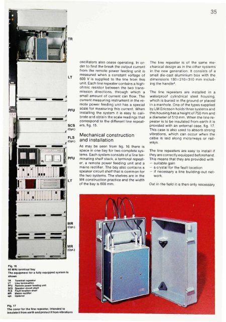
provided with an external case, fig. 17.<br />
This case is also used to absorb strong<br />
vibrations, which can occur when the<br />
cable is laid along motorways or railways.<br />
The line repeaters are easy to install if<br />
they are correctly equipped beforehand.<br />
This means that they are provided with<br />
— suitable gain<br />
— a crystal for the fault location<br />
— if necessary a line building-out network.<br />
Out in the field it is then only necessary<br />
Fig. 16<br />
60 MHz terminal bay<br />
The equipment for a fully equipped system is<br />
shown<br />
TR Terminal repeater<br />
LT Line termination<br />
PFU Remote power feeding unit<br />
SCS Speaker circuit shelf<br />
FLS Fault location shelf<br />
MR Mains rectifier<br />
opt Optional<br />
Fig. 17<br />
The cover for the line repeater, intended to<br />
Insulate it from earth and protect it from vibrations


