ABB-Welcome User Manual - Busch-Jaeger Elektro GmbH
ABB-Welcome User Manual - Busch-Jaeger Elektro GmbH
ABB-Welcome User Manual - Busch-Jaeger Elektro GmbH

Create successful ePaper yourself
Turn your PDF publications into a flip-book with our unique Google optimized e-Paper software.
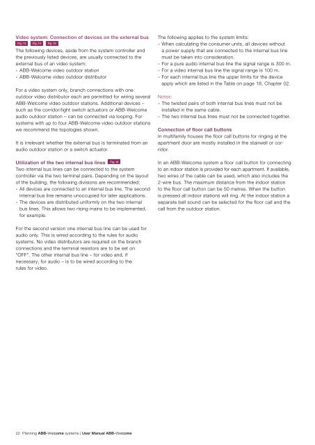
Video system: Connection of devices on the external bus<br />
Fig. 13 Fig. 14 Fig. 15<br />
The following devices, aside from the system controller and<br />
the previously listed devices, are usually connected to the<br />
external bus of an video system:<br />
» <strong>ABB</strong>-<strong>Welcome</strong> video outdoor station<br />
» <strong>ABB</strong>-<strong>Welcome</strong> video outdoor distributor<br />
For a video system only, branch connections with one<br />
outdoor video distributor each are permitted for wiring several<br />
<strong>ABB</strong>-<strong>Welcome</strong> video outdoor stations. Additional devices –<br />
such as the corridor/light switch actuators or <strong>ABB</strong>-<strong>Welcome</strong><br />
audio outdoor station – can be connected via looping. For<br />
systems with up to four <strong>ABB</strong>-<strong>Welcome</strong> video outdoor stations<br />
we recommend the topologies shown.<br />
It is irrelevant whether the external bus is terminated from an<br />
audio outdoor station or a switch actuator.<br />
Utilization of the two internal bus lines Fig. 16<br />
Two internal bus lines can be connected to the system<br />
controller via the two terminal pairs. Depending on the layout<br />
of the building, the following divisions are recommended:<br />
» All devices are connected to an internal bus line. The second<br />
internal bus line remains unoccupied for later applications.<br />
» The devices are distributed uniformly on the two internal<br />
bus lines. This allows two rising mains to be implemented,<br />
for example.<br />
For the second version one internal bus line can be used for<br />
audio only. This is wired according to the rules for audio<br />
systems. No video distributors are required on the branch<br />
connections and the terminal resistors are to be set on<br />
"OFF". The other internal bus line – for video and, if<br />
necessary, for audio – is to be wired according to the<br />
rules for video.<br />
22 Planning <strong>ABB</strong>-<strong>Welcome</strong> systems | <strong>User</strong> <strong>Manual</strong> <strong>ABB</strong>-<strong>Welcome</strong><br />
The following applies to the system limits:<br />
» When calculating the consumer units, all devices without<br />
a power supply that are connected to the internal bus line<br />
must be taken into consideration.<br />
» For a pure audio internal bus line the signal range is 300 m.<br />
» For a video internal bus line the signal range is 100 m.<br />
» For each internal bus line the upper limits for the device<br />
apply which are listed in the Table on page 18, Chapter 02.<br />
Notes:<br />
» The twisted pairs of both internal bus lines must not be<br />
installed in the same cable.<br />
» The two internal bus lines must not be connected together.<br />
Connection of floor call buttons<br />
In multifamily houses the floor call buttons for ringing at the<br />
apartment door are mostly installed in the stairwell or corridor.<br />
In an <strong>ABB</strong>-<strong>Welcome</strong> system a floor call button for connecting<br />
to an indoor station is provided for each apartment. If available,<br />
two wires of the cable can be used, which also includes the<br />
2-wire bus. The maximum distance from the indoor station<br />
to the floor call button can be 50 metres. When the button<br />
is pressed all indoor stations will ring. At the indoor station a<br />
separate bell sound can be selected for the floor call and the<br />
call from the outdoor station.