ABB-Welcome User Manual - Busch-Jaeger Elektro GmbH
ABB-Welcome User Manual - Busch-Jaeger Elektro GmbH
ABB-Welcome User Manual - Busch-Jaeger Elektro GmbH

Create successful ePaper yourself
Turn your PDF publications into a flip-book with our unique Google optimized e-Paper software.
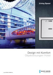
Door Communication<br />
<strong>ABB</strong>-<strong>Welcome</strong><br />
<strong>User</strong> <strong>Manual</strong>
The front door is the gateway between<br />
the outside world and your private living<br />
space. The modern door communication<br />
of <strong>ABB</strong>-<strong>Welcome</strong> now opens new<br />
possibilities for both sides – overall comfort,<br />
greater safety and stylistically matching<br />
design. The system harmoniously adapts<br />
to the architecture outdoors. In the<br />
interior area it can be uniformly matched<br />
with light switches and socket outlets.
<strong>User</strong> <strong>Manual</strong> <strong>ABB</strong>-<strong>Welcome</strong> | 3
Most welcome.<br />
Intelligence with system.<br />
4 | <strong>User</strong> <strong>Manual</strong> <strong>ABB</strong>-<strong>Welcome</strong>
<strong>ABB</strong>-<strong>Welcome</strong>. The new door communication from <strong>ABB</strong>, the<br />
leading brand with in home technology and innovative solutions<br />
for intelligent building automation. The new product range <strong>ABB</strong>-<br />
<strong>Welcome</strong> supplements the comprehensive range in a practical<br />
way. It sets new standards as a holistic system. It combines<br />
perfect design, comfort, efficiency and security. Living space<br />
can now be consistently and uniformly designed. From the light<br />
switch up to door communication. Inside and outside.<br />
<strong>User</strong> <strong>Manual</strong> <strong>ABB</strong>-<strong>Welcome</strong> | 5
Door to door.<br />
Technology and progress.<br />
01<br />
The right solution for every requirement. With the wide range<br />
of well-designed products, optimum door communication can<br />
be made a reality for all types of buildings. Without great effort<br />
due to the 2-wire bus technique. And always with high-quality<br />
materials that are carefully matched. This makes <strong>ABB</strong>-<strong>Welcome</strong><br />
ideal for use in new buildings as well as the later integration<br />
during the modernization of all types of real estate.<br />
6 | <strong>User</strong> <strong>Manual</strong> <strong>ABB</strong>-<strong>Welcome</strong><br />
02
03<br />
04<br />
01 <strong>ABB</strong>-<strong>Welcome</strong> Video outdoor station<br />
02 <strong>ABB</strong>-<strong>Welcome</strong>Touch<br />
03 <strong>ABB</strong>-<strong>Welcome</strong> audio indoor station with handset<br />
04 <strong>ABB</strong>-<strong>Welcome</strong> audio indoor station with display<br />
<strong>User</strong> <strong>Manual</strong> <strong>ABB</strong>-<strong>Welcome</strong> | 7
8 | <strong>User</strong> <strong>Manual</strong> <strong>ABB</strong>-<strong>Welcome</strong>
Contents<br />
01 Examples for typical <strong>ABB</strong>-<strong>Welcome</strong> systems 10<br />
02 Planning <strong>ABB</strong>-<strong>Welcome</strong> systems 14<br />
03 Installation 30<br />
04 Commissioning 36<br />
05 Operation 42<br />
06 Overview of product range 44<br />
07 Connection diagrams 52<br />
Legend 56<br />
<strong>User</strong> <strong>Manual</strong> <strong>ABB</strong>-<strong>Welcome</strong> | 9
01<br />
The ideal system for every building<br />
More is possible. <strong>ABB</strong>-<strong>Welcome</strong> systems offer flexible<br />
solutions. Planning is made as simple for you as are installation<br />
or commissioning. The 2-wire bus technique makes possible<br />
the suitable layout – to fully meet the requirements of the user.<br />
One-family house, audio/video Fig. 1<br />
<strong>ABB</strong>-<strong>Welcome</strong> systems consist at least of a system controller,<br />
outdoor station and indoor station. In Fig. 1 three indoor<br />
stations are installed in the one house. When a visitor rings<br />
the bell at the <strong>ABB</strong>-<strong>Welcome</strong> video outdoor station, the call<br />
can be answered either at the <strong>ABB</strong>-<strong>Welcome</strong>Touch, at the<br />
<strong>ABB</strong>-<strong>Welcome</strong> audio indoor station with display or the <strong>ABB</strong>-<br />
<strong>Welcome</strong> audio indoor station with handset.<br />
01 One-family house<br />
02 Multifamily house<br />
01<br />
10 Examples for typical <strong>ABB</strong>-<strong>Welcome</strong> systems | <strong>User</strong> <strong>Manual</strong> <strong>ABB</strong>-<strong>Welcome</strong><br />
Multifamily house, audio Fig. 2<br />
Retrofitting an <strong>ABB</strong>-<strong>Welcome</strong> system in a multifamily house<br />
with existing wiring is very easy. Even a plain bell system<br />
can be converted to audio or video. Depending on the local<br />
circumstances, an installation with recourse to a rising mains,<br />
as shown in Figure 2, is recommended. The wires branch off<br />
on each floor where the existing apartments are located –<br />
to where an audio indoor station with handset is mounted.<br />
There the user can answer incoming calls, open the door and<br />
switch on the lights in the stairwell. Also floor call buttons can<br />
be used. These are connected to the indoor station.<br />
02
Fig. 1<br />
One-family house/villa<br />
» System type: audio/video combined<br />
» Wiring: looped from device to device<br />
» Devices used<br />
» One <strong>ABB</strong>-<strong>Welcome</strong> video outdoor station, 1gang,<br />
article number: 83121/1-xxx-500<br />
» One <strong>ABB</strong>-<strong>Welcome</strong> audio indoor station with display,<br />
article number: 83200 U-500,<br />
cover plates article number: 83260-xxx-500 2gang frame<br />
» One <strong>ABB</strong>-<strong>Welcome</strong> audio indoor station with handset,<br />
article number: 83205 AP-xxx-500<br />
» One <strong>ABB</strong>-<strong>Welcome</strong>Touch,<br />
article number: 83220 AP-xxx-500<br />
» One <strong>ABB</strong>-<strong>Welcome</strong> system controller,<br />
article number: 83300-500<br />
» One electric door opener<br />
The combined audio/video solution for the one-family house.<br />
The drawing shows the easy-to-install 2-wire bus. From the<br />
<strong>ABB</strong>-<strong>Welcome</strong> video outdoor station to the <strong>ABB</strong>-<strong>Welcome</strong> system<br />
controller. And from there to the <strong>ABB</strong>-<strong>Welcome</strong>Touch as well as<br />
to the <strong>ABB</strong>-<strong>Welcome</strong> audio indoor station with display and the<br />
<strong>ABB</strong>-<strong>Welcome</strong> audio indoor station with handset. Additional<br />
distributors are not required.<br />
Fig. 2<br />
Multifamily house with 4 private apartments<br />
» System type: audio<br />
» Wiring: rising mains with branch connections<br />
» Devices used<br />
» One <strong>ABB</strong>-<strong>Welcome</strong> audio outdoor station, 4gang,<br />
article number: 83102/4-xxx-500<br />
» Four <strong>ABB</strong>-<strong>Welcome</strong> audio indoor stations with handset,<br />
article number: 83205 AP-xxx-500<br />
» One <strong>ABB</strong>-<strong>Welcome</strong> system controller,<br />
article number: 83300-500<br />
» Four floor call buttons<br />
» One electric door opener<br />
The audio solution for the multifamily house. The drawing shows<br />
the easy-to-install 2-wire bus From the <strong>ABB</strong>-<strong>Welcome</strong> outdoor<br />
audio station to the <strong>ABB</strong>-<strong>Welcome</strong> system controller. And from<br />
there to the <strong>ABB</strong>-<strong>Welcome</strong> audio indoor station with handset.<br />
Additional distributors are not required<br />
Note: Graphic symbols are explained in the legend on page 56.<br />
S<br />
<strong>User</strong> <strong>Manual</strong> <strong>ABB</strong>-<strong>Welcome</strong> | Examples for typical <strong>ABB</strong>-<strong>Welcome</strong> systems 11<br />
S
Multifamily house, audio/video Fig. 3<br />
The setup of a video system or a combined audio/video<br />
system can include an existing rising mains. To correctly<br />
distribute the video image of the outdoor station inside the<br />
house, flush-mounted video distributors are installed in each<br />
branch box. Or MDRC units can be used in existing subdistributions.<br />
01 Multifamily house<br />
02 Commercial object<br />
01<br />
12 Examples for typical <strong>ABB</strong>-<strong>Welcome</strong> systems | <strong>User</strong> <strong>Manual</strong> <strong>ABB</strong>-<strong>Welcome</strong><br />
Commercial object, audio/video Fig. 4<br />
For buildings with several entrances (doctor's office, law firm,<br />
small workshops, or similar), these can be individually equipped<br />
with <strong>ABB</strong>-<strong>Welcome</strong> outdoor stations. A combination of <strong>ABB</strong>-<br />
<strong>Welcome</strong> audio outdoor stations and <strong>ABB</strong>-<strong>Welcome</strong> video<br />
outdoor stations is possible. For this a video outdoor distributor<br />
as MDRC unit must be used. The door – from which the bell is<br />
rung – is opened from the indoor station called.<br />
02
Fig. 3<br />
Multifamily house with 6 private apartments<br />
» System type: audio/video combined<br />
» Wiring: rising mains with branch connections, i.e. video<br />
distributors<br />
» Devices used:<br />
» One <strong>ABB</strong>-<strong>Welcome</strong> video outdoor station,<br />
6gang, article number: 83122/6-xxx-500<br />
» Four <strong>ABB</strong>-<strong>Welcome</strong> audio indoor stations with handset,<br />
article number: 83205 AP-xxx-500<br />
» Two <strong>ABB</strong>-<strong>Welcome</strong>Touch,<br />
article number: 83220 AP-xxx-500<br />
» <strong>ABB</strong>-<strong>Welcome</strong> system controller,<br />
article number: 83300-500<br />
» Three <strong>ABB</strong>-<strong>Welcome</strong> video distributors, FM indoor,<br />
article number: 83320/2 U-500<br />
» Six floor call buttons<br />
» One electric door opener<br />
The combined audio/video solution for the multifamily house<br />
with six private apartments. The wiring from the <strong>ABB</strong>-<strong>Welcome</strong><br />
system controller to the indoor stations is designed as rising<br />
mains. From here the wires branch off into the apartments. Each<br />
of the two bottom floors has an <strong>ABB</strong>-<strong>Welcome</strong> audio indoor station<br />
with handset installed. All branch connections require video<br />
distributors.<br />
Fig. 4<br />
Commercial object<br />
» System type: audio/video<br />
» Wiring: looped from device to device<br />
» Devices used<br />
» One <strong>ABB</strong>-<strong>Welcome</strong> video outdoor station, 1gang,<br />
article number: 83121/1-xxx-500<br />
» One <strong>ABB</strong>-<strong>Welcome</strong> audio outdoor station, 1gang,<br />
article number: 83101/1-xxx-500<br />
» One <strong>ABB</strong>-<strong>Welcome</strong> audio indoor station with display,<br />
article number: 83200 U, cover plates article number:<br />
83260-xxx-500 2gang frame<br />
» One <strong>ABB</strong>-<strong>Welcome</strong>Touch,<br />
article number: 83220 AP-xxx-500<br />
» One <strong>ABB</strong>-<strong>Welcome</strong> system controller,<br />
article number: 83300-500<br />
» One <strong>ABB</strong>-<strong>Welcome</strong> video outdoor distributor,<br />
article number: 83325/2-500<br />
» One <strong>ABB</strong>-<strong>Welcome</strong> bell transformer,<br />
article number: 83315-500<br />
» One switch actuator, door/light,<br />
article number: 83330-500<br />
» Two electric door openers<br />
The combined audio/video solution for a building with several<br />
entrances – such as private apartment and office. One indoor<br />
station is located on the left at the office entrance, another one<br />
on the right at the apartment. Inside the building the two internal<br />
bus lines of the system controller are used. A distributor is<br />
required to connect the two outdoor stations.<br />
S<br />
D<br />
D<br />
D<br />
S<br />
D out<br />
<strong>User</strong> <strong>Manual</strong> <strong>ABB</strong>-<strong>Welcome</strong> | Examples for typical <strong>ABB</strong>-<strong>Welcome</strong> systems 13<br />
in<br />
in<br />
in<br />
A
02<br />
Assistance for planning.<br />
Early advantage: With the planning aids for <strong>ABB</strong>-<strong>Welcome</strong>.<br />
This makes even complex projects easy to manage and easy<br />
to implement at a later stage.<br />
The <strong>ABB</strong>-<strong>Welcome</strong> door communication can be used purely<br />
as a 2-wire bus system in new buildings and for modernizing<br />
existing systems. In most cases, the existing lines can be<br />
used. The universally used 2-wire bus technology allows a<br />
bell system to be upgraded to a video system with outdoor<br />
camera.<br />
An <strong>ABB</strong>-<strong>Welcome</strong> system can be set up purely as an audio<br />
system. Visitors and residents use it to communicate with<br />
each other between outdoor station and indoor station. Or<br />
it can be a video system. This makes the camera image of<br />
the video outdoor station visible on the <strong>ABB</strong>-<strong>Welcome</strong>Touch.<br />
Video and audio units can also be installed in the same<br />
system. Also the later exchange of audio units with video<br />
units, and the reverse, is possible.*<br />
An <strong>ABB</strong>-<strong>Welcome</strong> system is made up of the following units:<br />
» One or more outdoor stations<br />
» One or more indoor stations<br />
» The system controller<br />
» And, if required, additional system devices<br />
All units are connected with each other via the <strong>ABB</strong>-<strong>Welcome</strong><br />
2-wire bus.<br />
* The special system topology of a video system is to be observed (S. 20, Chapter. 02).<br />
** The actual number of apartments is limited by the available bell buttons.<br />
14 Planning <strong>ABB</strong>-<strong>Welcome</strong> systems | <strong>User</strong> <strong>Manual</strong> <strong>ABB</strong>-<strong>Welcome</strong><br />
Equipping apartments and entrances with indoor or<br />
outdoor stations<br />
With an <strong>ABB</strong>-<strong>Welcome</strong> system buildings can be upgraded<br />
from a one-family house to a large multifamily house. On the<br />
one system up to 15 apartments with audio applications (up<br />
to 12 apartments with video or mixed applications) can have<br />
their own bell connected to the outdoor station.**<br />
Up to four different indoor stations can be installed in each<br />
apartment. They are assigned the same address and ring<br />
simultaneously at an incoming call. Also several indoor<br />
stations with different addresses can be installed in the<br />
one private apartment.<br />
In one <strong>ABB</strong>-<strong>Welcome</strong> system up to four different entrances<br />
can be equipped with outdoor stations. The doors can be<br />
opened remote-controlled. The associated lighti ng can also<br />
be switched.<br />
A flexible system. Also for residential buildings with<br />
integrated medical and legal and other offices.
<strong>User</strong> <strong>Manual</strong> <strong>ABB</strong>-<strong>Welcome</strong> | Planning <strong>ABB</strong>-<strong>Welcome</strong> systems 15
Options of flexible addressing<br />
Assigning doorbell push-buttons to apartments<br />
The doorbell push-buttons of an outdoor station can be freely<br />
assigned to an apartment. When the doorbell push-button is<br />
pressed the call is received at the fixed address. The option<br />
of flexible addressing allows the <strong>ABB</strong>-<strong>Welcome</strong> system to<br />
be adapted to the individual requirements of the user. This<br />
is a big advantage – especially when a system has several<br />
outdoor stations.<br />
The use of several outdoor stations: uniform assignment<br />
of call buttons Fig. 5<br />
With several outdoor stations within an <strong>ABB</strong>-<strong>Welcome</strong> system<br />
the call buttons of each outdoor station are generally assigned<br />
similarly. This means that all apartments can be called from<br />
all outdoor stations. This is practical for buildings with several<br />
entrances – from each of which all apartments are accessible.<br />
Several outdoor stations with different bell fields Fig. 6<br />
Alternatively, the call buttons of the various outdoor stations<br />
can be assigned differently when all apartments are to be<br />
called from one outdoor station and only some apartments<br />
from additional outdoor stations.<br />
In the example an outdoor station is mounted at the gate<br />
entrance with which all four apartments can be called. One<br />
outdoor station is on the left building with apartments 01 and<br />
02 and a further outdoor station on the right building with<br />
apartments 03 and 04. This means that only two apartments<br />
can be called from these two outdoor stations.<br />
The use of several outdoor stations: assigning the<br />
standard outdoor station<br />
The <strong>ABB</strong>-<strong>Welcome</strong> system guarantees the opening of the<br />
door at several outdoor stations at which the visitor has rung<br />
the bell. The resident simply presses the button "Open door"<br />
at the indoor station. Also the associated light at the entrance<br />
can be switched on. Opening and switching in the apartment<br />
is also possible without an existing outside call.<br />
For several entrances with a system with outdoor stations, one<br />
standard outdoor station is defined for opening the door and<br />
switching the light. The setting is made at the indoor stations of<br />
each apartment. With the <strong>ABB</strong>-<strong>Welcome</strong>Touch the camera image<br />
of an outdoor station can also be activated without having<br />
received a call. Here the camera image of the standard outdoor<br />
station is displayed.<br />
* Detailed information about calculations, starting from page 24, Chapter 02.<br />
16 Planning <strong>ABB</strong>-<strong>Welcome</strong> systems | <strong>User</strong> <strong>Manual</strong> <strong>ABB</strong>-<strong>Welcome</strong><br />
System controller and auxiliary power supply Fig. 7<br />
The system controller supplies the other bus subscribers with<br />
voltage and controls communication on the 2-wire bus. Starting<br />
from the system controller, the 2-wire bus divides into three<br />
bus lines, the external bus and the two internal bus lines.<br />
The <strong>ABB</strong>-<strong>Welcome</strong> system controller additionally offers options<br />
for connecting a door opener and hallway or path illumination.<br />
The switching times can be set on the device.<br />
These hints should definitely be observed to prevent faults<br />
from occurring during the audio and video transmission.<br />
Notes:<br />
» All branches of the wiring system should be terminated by<br />
a connected bus device (e.g., an indoor station, outdoor<br />
station or a system device). This means that no branches<br />
are to be open.<br />
» The system controller should not be installed in the<br />
immediate vicinity of bell transformers or other switched<br />
power supplies to prevent interference.<br />
» Do not install the lines of the system bus together with<br />
230 V cables.<br />
» Connection cables for door openers should not be placed<br />
in the same cable as the lines of the 2-wire bus.<br />
» Avoid transitions between different cable types.<br />
» In a cable with four or more wires, only one pair of wires<br />
should be used for the 2-wire bus.<br />
» When looping the 2-wire bus to a bus that is incoming or<br />
outgoing from a device, it should not be installed in the<br />
same cable.<br />
» Internal and external bus must not laid in the same cable.<br />
A system controller makes 65 consumer units available to the<br />
<strong>ABB</strong>-<strong>Welcome</strong>. They are used to supply the connected devices.<br />
In a one-family house, for example, this allows one video<br />
outdoor station as well as up to four <strong>ABB</strong>-<strong>Welcome</strong>Touch<br />
to be operated.<br />
In a multifamily house, for example, this allows a system with<br />
one <strong>ABB</strong>-<strong>Welcome</strong> audio outdoor station with 15 bell buttons<br />
and 30 audio indoor stations with handset (i.e. two per<br />
apartment) to be operated by one system controller. For a<br />
larger number of units an auxiliary power supply is required.*
Fig. 5<br />
The use of several outdoor stations: uniform assignment<br />
of call buttons<br />
Outdoor station<br />
Main entrance<br />
Fig. 6<br />
Apartment 01 A<br />
Apartment 02 B<br />
Apartment 03 C<br />
Apartment 01 A<br />
Apartment 02 B<br />
Apartment 03 C<br />
Outdoor station<br />
Side entrance<br />
Several outdoor stations with different bell<br />
fields<br />
Apartment 01Apartment<br />
A 01 A Apartment 01Apartment<br />
A 01 A Apartment 03Apartment<br />
A 03 A<br />
Apartment 02Apartment B 02 B Apartment 02Apartment B 02 B Apartment 04Apartment B 04 B<br />
Apartment 03Apartment<br />
C 03 C<br />
Apartment 04Apartment D 04 D<br />
Outdoor Outdoor station station Outdoor Outdoor station station Outdoor Outdoor station station<br />
Left building Left building Gateway Gateway entrance entrance Right building Right building<br />
Fig. 7<br />
The system controller<br />
232 V AC<br />
2<br />
Internal bus<br />
Line 1<br />
2<br />
S<br />
2<br />
External bus<br />
Internal bus<br />
Line 2<br />
2<br />
2<br />
2<br />
2<br />
Electronic door opener<br />
8-12V AC<br />
Electronic door opener<br />
(relay contact)<br />
Hallway light<br />
(relay contact)<br />
<strong>User</strong> <strong>Manual</strong> <strong>ABB</strong>-<strong>Welcome</strong> | Planning <strong>ABB</strong>-<strong>Welcome</strong> systems 17
Auxiliary power supplies<br />
Auxiliary power supplies can be connected to the internal bus<br />
lines at any position. They serve for the connection of indoor<br />
stations. One auxiliary power supply makes available 45 consumer<br />
units. Neither they nor the connected devices put a load on the<br />
system controller.<br />
The use of auxiliary power supplies increases the number of<br />
devices in a system. The maximum signal range – measured<br />
from the system controller – is not increased. The indoor<br />
stations can be connected to each of the four outputs of the<br />
auxiliary power supply. A uniform distribution of the outputs is<br />
recommended.<br />
Cable type and signal ranges<br />
The following cable types with a diameter of 0.8 mm are<br />
recommended:<br />
» Telecommunication lines J-Y(St)-Y<br />
» Bell lines YR<br />
» Telecommunication lines for outdoor A-2Y(L)2Y<br />
The following cable types should not be used:<br />
» Antenna cables<br />
» NYM cables<br />
» Riser cables<br />
» Cable with a diameter smaller than 0.6 mm<br />
The signal ranges for bus lines<br />
The length of cables for the system controller to the remotest<br />
indoor station or outdoor station must not exceed the following<br />
values:<br />
Bus lines<br />
Connected<br />
indoor or<br />
outdoor stations Signal range<br />
External bus Audio 300 m<br />
External bus Audio/Video 100 m*<br />
Internal bus line 1 Audio 300 m<br />
Internal bus line 1 Audio/Video 100 m<br />
Internal bus line 2 Audio 300 m<br />
Internal bus line 2 Audio/Video 100 m<br />
* When connecting only one <strong>ABB</strong>-<strong>Welcome</strong> video outdoor station to<br />
the external bus line the signal range is 150 m.<br />
Note: The two separate internal bus lines 1 and 2 permit the<br />
setup of a pure audio line with a signal range of 300 m and<br />
an audio/video line with a signal range of 100 m.<br />
18 Planning <strong>ABB</strong>-<strong>Welcome</strong> systems | <strong>User</strong> <strong>Manual</strong> <strong>ABB</strong>-<strong>Welcome</strong><br />
Maximum number of devices per internal bus line<br />
The maximum number of devices per internal bus line must<br />
be observed. It is dependent on the power consumption of<br />
the connected indoor stations:<br />
Connected device type<br />
<strong>ABB</strong>-<strong>Welcome</strong> audio<br />
indoor station with<br />
handset<br />
<strong>ABB</strong>-<strong>Welcome</strong> audio<br />
indoor station with<br />
display<br />
<strong>ABB</strong>-<strong>Welcome</strong> audio<br />
indoor station with<br />
display<br />
<strong>ABB</strong>-<strong>Welcome</strong> audio<br />
indoor station with<br />
display<br />
<strong>ABB</strong>-<strong>Welcome</strong> IP<br />
gateway for<br />
<strong>Busch</strong>-ComfortTouch ®<br />
Maximum number of<br />
indoor stations<br />
30 devices 300 m<br />
30 devices 100 m*<br />
6 devices 200 m*<br />
4 devices 300 m<br />
4 devices<br />
Maximum cable length<br />
between power supply<br />
and the remotest<br />
indoor station<br />
100 m<br />
<strong>ABB</strong>-<strong>Welcome</strong>Touch 4 devices 100 m<br />
* The shortened length of cable in comparison to the signal range of the<br />
<strong>ABB</strong>-<strong>Welcome</strong> indoor audio station with display results from the increase<br />
in current consumption in comparison to the <strong>ABB</strong>-<strong>Welcome</strong> audio indoor<br />
station with handset. When the maximum number of devices at the system<br />
controller is exceeded, an auxiliary power supply must be used. In turn, for<br />
each of the four outputs of the auxiliary power supply the number of devices<br />
and limits of cable length specified in the table apply.<br />
Note: The maximum cable length specified applies to cables with<br />
a diameter of 0.8 mm. For a diameter of 0.6 mm the length of<br />
cable is halved.
Topology rules for the internal and external bus<br />
Indoor stations, outdoor stations and system devices must<br />
be connected to the system controller according to topology<br />
rules for <strong>ABB</strong>-<strong>Welcome</strong> systems.<br />
Topology rules for audio systems Topology rules for<br />
audio systems Fig. 8 Fig. 9<br />
For planning an <strong>ABB</strong>-<strong>Welcome</strong> audio system in which, next<br />
to control information, only one audio signal is transmitted on<br />
a 2-wire bus.<br />
Audio system: Connection of devices on the internal bus<br />
The following devices, aside from the system controller, are<br />
usually connected to the internal bus of an audio system:<br />
» <strong>ABB</strong>-<strong>Welcome</strong> audio indoor station with handset<br />
» <strong>ABB</strong>-<strong>Welcome</strong> audio indoor station with display<br />
» <strong>ABB</strong>-<strong>Welcome</strong> auxiliary power supply<br />
There are two options for wiring the devices: Looping and<br />
branch line connections ("stub lines"). Both versions can be<br />
combined within the one system.<br />
Note: For all devices the terminal resistor should not be<br />
activated – the switch "RC" is always on "OFF".<br />
Fig. 8<br />
AUDIO<br />
S<br />
AUDIO<br />
AUDIO<br />
AUDIO<br />
AUDIO<br />
RC – OFF<br />
RC – OFF<br />
RC – OFF<br />
RC – OFF<br />
Audio system: Looping the internal bus<br />
For looping a continuous bus line the incoming and outgoing<br />
2-wire bus is connected at each device as shown in Fig. 8.<br />
A device must be connected to the end of the bus line – so<br />
that the bus line does not remain "open". In all devices of the<br />
audio system the terminal resistor should not be activated –<br />
the switch "RC" is always on "OFF". Fig. 8<br />
Audio system: Internal bus stub lines<br />
As an alternative to looping, the devices can also be<br />
connected at the end of a branch line or stub line:<br />
» <strong>ABB</strong>-<strong>Welcome</strong> audio indoor station with handset<br />
» <strong>ABB</strong>-<strong>Welcome</strong> audio indoor station with display<br />
» <strong>ABB</strong>-<strong>Welcome</strong> auxiliary power supply<br />
An example of this layout: A rising mains in a building<br />
connects the floors and the stub lines branch off on the<br />
floors. Fig. 9<br />
A topology with a rising mains and several stub lines can<br />
easily be set up in an audio system. Here the bus lines are<br />
switched parallel to the branch connections.<br />
Audio system: Looping the internal bus Audio system: Internal bus stub line<br />
Fig. 9<br />
RC – OFF<br />
RC – OFF<br />
RC – OFF<br />
RC – OFF<br />
AUDIO<br />
AUDIO<br />
AUDIO<br />
AUDIO<br />
AUDIO<br />
S<br />
AUDIO<br />
AUDIO<br />
AUDIO<br />
AUDIO<br />
RC – OFF<br />
RC – OFF<br />
RC – OFF<br />
RC – OFF<br />
<strong>User</strong> <strong>Manual</strong> <strong>ABB</strong>-<strong>Welcome</strong> | Planning <strong>ABB</strong>-<strong>Welcome</strong> systems 19
Audio system: Connection of devices to the external bus<br />
Fig. 10<br />
The following devices, aside from the system controller, are<br />
usually connected to the external bus of an audio system:<br />
» <strong>ABB</strong>-<strong>Welcome</strong> audio outdoor station<br />
» Switch actuator, door/light<br />
Up to four outdoor stations can be connected. For each of<br />
these, two switch actuators for opening doors and switching<br />
lights can be used. When installing only one outdoor station,<br />
the door opening or light function of the system controller can<br />
be used.<br />
The connection is made directly on their external bus. With<br />
two or more outdoor stations, star-shaped wiring is to be<br />
selected. The star point is to be located as close to the<br />
system controller as possible. Fig. 10<br />
It is irrelevant whether the external bus is terminated from an<br />
audio outdoor station or a switch actuator.<br />
Note: Neither the <strong>ABB</strong>-<strong>Welcome</strong> audio outdoor station nor<br />
the switch actuator have a switch for the terminal resistor.<br />
20 Planning <strong>ABB</strong>-<strong>Welcome</strong> systems | <strong>User</strong> <strong>Manual</strong> <strong>ABB</strong>-<strong>Welcome</strong><br />
Topology rules for video systems<br />
An <strong>ABB</strong>-<strong>Welcome</strong> video system with transmission of the<br />
control information, of the audio signal as well as the video<br />
signal is planned as follows:<br />
Video system: Connection of devices on the internal bus<br />
The devices used for setting up an audio system can also be<br />
used for setting up a video system. This means system<br />
controller, <strong>ABB</strong>-<strong>Welcome</strong> audio outdoor station and audio<br />
indoor station. And, depending on the layout, the following<br />
devices are additionally connected to the internal bus.<br />
» <strong>ABB</strong>-<strong>Welcome</strong>Touch<br />
» <strong>ABB</strong>-<strong>Welcome</strong> IP gateway<br />
» Video indoor distributor<br />
Fig. 11<br />
Video system: Looping the internal bus<br />
The 2-wire bus for a video system can be looped from device<br />
to device similar to an audio system. This results in a continuous<br />
bus line.<br />
The terminal resistor must be activated on the last device of<br />
the bus line – the switch "RC" is set to "ON". For all other<br />
devices the switch is set on "OFF".<br />
Video system: Internal bus stub lines Fig. 12<br />
As an alternative to looping, the devices can also be<br />
connected at the video system via stub line. In this case a<br />
video distributor is to be used on all branch connections.<br />
The video indoor distributor exist as MDRC unit for mounting<br />
in a sub-distribution or as built-in device for flush-mounted<br />
installation in a branch box. The terminal resistor must be<br />
activated on the last device of each stub line and at the end<br />
of the riser main – the switch "RC" is set to "ON".
Fig. 10<br />
Audio system: Two outdoor stations<br />
AUDIO<br />
Fig. 11<br />
A<br />
S<br />
S<br />
AUDIO<br />
AUDIO<br />
Video system: Looping the internal bus<br />
VIDEO<br />
RC – ON<br />
VIDEO<br />
RC – OFF<br />
AUDIO<br />
RC – OFF<br />
VIDEO<br />
RC – OFF<br />
AUDIO<br />
RC – OFF<br />
RC – OFF<br />
AUDIO<br />
Fig. 12<br />
Video system: Internal bus stub lines<br />
RC – ON<br />
RC – ON<br />
RC – ON<br />
RC – ON<br />
VIDEO<br />
AUDIO<br />
VIDEO<br />
AUDIO<br />
AUDIO<br />
D<br />
in RC – ON<br />
D<br />
in RC – OFF<br />
D<br />
in RC – OFF<br />
D<br />
in RC – OFF<br />
S<br />
AUDIO<br />
AUDIO<br />
RC – ON<br />
VIDEO<br />
AUDIO<br />
RC – ON<br />
RC – ON<br />
RC – ON<br />
<strong>User</strong> <strong>Manual</strong> <strong>ABB</strong>-<strong>Welcome</strong> | Planning <strong>ABB</strong>-<strong>Welcome</strong> systems 21
Video system: Connection of devices on the external bus<br />
Fig. 13 Fig. 14 Fig. 15<br />
The following devices, aside from the system controller and<br />
the previously listed devices, are usually connected to the<br />
external bus of an video system:<br />
» <strong>ABB</strong>-<strong>Welcome</strong> video outdoor station<br />
» <strong>ABB</strong>-<strong>Welcome</strong> video outdoor distributor<br />
For a video system only, branch connections with one<br />
outdoor video distributor each are permitted for wiring several<br />
<strong>ABB</strong>-<strong>Welcome</strong> video outdoor stations. Additional devices –<br />
such as the corridor/light switch actuators or <strong>ABB</strong>-<strong>Welcome</strong><br />
audio outdoor station – can be connected via looping. For<br />
systems with up to four <strong>ABB</strong>-<strong>Welcome</strong> video outdoor stations<br />
we recommend the topologies shown.<br />
It is irrelevant whether the external bus is terminated from an<br />
audio outdoor station or a switch actuator.<br />
Utilization of the two internal bus lines Fig. 16<br />
Two internal bus lines can be connected to the system<br />
controller via the two terminal pairs. Depending on the layout<br />
of the building, the following divisions are recommended:<br />
» All devices are connected to an internal bus line. The second<br />
internal bus line remains unoccupied for later applications.<br />
» The devices are distributed uniformly on the two internal<br />
bus lines. This allows two rising mains to be implemented,<br />
for example.<br />
For the second version one internal bus line can be used for<br />
audio only. This is wired according to the rules for audio<br />
systems. No video distributors are required on the branch<br />
connections and the terminal resistors are to be set on<br />
"OFF". The other internal bus line – for video and, if<br />
necessary, for audio – is to be wired according to the<br />
rules for video.<br />
22 Planning <strong>ABB</strong>-<strong>Welcome</strong> systems | <strong>User</strong> <strong>Manual</strong> <strong>ABB</strong>-<strong>Welcome</strong><br />
The following applies to the system limits:<br />
» When calculating the consumer units, all devices without<br />
a power supply that are connected to the internal bus line<br />
must be taken into consideration.<br />
» For a pure audio internal bus line the signal range is 300 m.<br />
» For a video internal bus line the signal range is 100 m.<br />
» For each internal bus line the upper limits for the device<br />
apply which are listed in the Table on page 18, Chapter 02.<br />
Notes:<br />
» The twisted pairs of both internal bus lines must not be<br />
installed in the same cable.<br />
» The two internal bus lines must not be connected together.<br />
Connection of floor call buttons<br />
In multifamily houses the floor call buttons for ringing at the<br />
apartment door are mostly installed in the stairwell or corridor.<br />
In an <strong>ABB</strong>-<strong>Welcome</strong> system a floor call button for connecting<br />
to an indoor station is provided for each apartment. If available,<br />
two wires of the cable can be used, which also includes the<br />
2-wire bus. The maximum distance from the indoor station<br />
to the floor call button can be 50 metres. When the button<br />
is pressed all indoor stations will ring. At the indoor station a<br />
separate bell sound can be selected for the floor call and the<br />
call from the outdoor station.
Fig. 13<br />
Video system: Two outdoor stations<br />
VIDEO<br />
Fig. 15<br />
Fig. 16<br />
RC – OFF<br />
AUDIO AUDIO<br />
RC – OFF<br />
RC – ON<br />
RC – ON<br />
AUDIO<br />
VIDEO<br />
D<br />
in RC – ON<br />
D<br />
in RC – OFF<br />
RC – OFF RC – OFF<br />
RC – ON<br />
D<br />
in RC – OFF<br />
AUDIO<br />
AUDIO<br />
AUDIO<br />
VIDEO<br />
A<br />
Audio/video system: Utilization of the two internal bus lines<br />
S<br />
VIDEO<br />
VIDEO<br />
D out<br />
Video system: Four outdoor stations<br />
D out<br />
A<br />
A<br />
S<br />
D out<br />
VIDEO<br />
VIDEO<br />
D out<br />
VIDEO<br />
S<br />
A<br />
VIDEO<br />
VIDEO<br />
Fig. 14<br />
Video system: Three outdoor stations<br />
VIDEO<br />
S<br />
D out<br />
RC – ON<br />
VIDEO<br />
AUDIO<br />
AUDIO<br />
RC – ON<br />
RC – ON<br />
D out<br />
A<br />
A<br />
VIDEO<br />
VIDEO<br />
<strong>User</strong> <strong>Manual</strong> <strong>ABB</strong>-<strong>Welcome</strong> | Planning <strong>ABB</strong>-<strong>Welcome</strong> systems 23
Planning simple systems<br />
One-family house with four indoor stations Fig. 17<br />
An <strong>ABB</strong>-<strong>Welcome</strong> system with up to four indoor stations can<br />
be set up in a one-family house without further calculation.<br />
Also up to four <strong>ABB</strong>-<strong>Welcome</strong>Touch can be connected to the<br />
system controller.<br />
Multifamily houses<br />
The following table serves to calculate the maximum number<br />
of devices with power supply in multifamily houses.<br />
Note: The table applies only to apartments with one to two<br />
indoor stations.<br />
Calculation of consumption for system controller<br />
Device<br />
Indoor stations<br />
Number Consumption units<br />
<strong>ABB</strong>-<strong>Welcome</strong> audio indoor station with handset 1<br />
<strong>ABB</strong>-<strong>Welcome</strong> audio indoor station with display 2<br />
<strong>ABB</strong>-<strong>Welcome</strong>Touch 11<br />
<strong>ABB</strong>-<strong>Welcome</strong> IP gateway for <strong>Busch</strong>-ComfortTouch ® Video outdoor stations<br />
11<br />
<strong>ABB</strong>-<strong>Welcome</strong> video outdoor station, 1gang, 2gang, 3-gang 8<br />
<strong>ABB</strong>-<strong>Welcome</strong> video outdoor station, 4gang, 6gang 10<br />
<strong>ABB</strong>-<strong>Welcome</strong> video outdoor station, 8gang, 12gang<br />
Audio outdoor station<br />
13<br />
<strong>ABB</strong>-<strong>Welcome</strong> audio outdoor station, 1gang, 2gang, 3-gang 5<br />
<strong>ABB</strong>-<strong>Welcome</strong> audio outdoor station, 4gang, 6gang 6<br />
<strong>ABB</strong>-<strong>Welcome</strong> audio outdoor station, 10gang, 15gang<br />
System devices<br />
11<br />
<strong>ABB</strong>-<strong>Welcome</strong> door/light switch actuators<br />
Only for two indoor stations per apartment<br />
2<br />
Number of apartments with two audio indoor stations 1 or 2<br />
Number of apartments with one audio indoor station and one<br />
<strong>ABB</strong>-<strong>Welcome</strong>Touch<br />
1 or 2<br />
Number of apartments with two <strong>ABB</strong>-<strong>Welcome</strong>Touch<br />
Total number of consumer units<br />
must not exceed 65<br />
24 Planning <strong>ABB</strong>-<strong>Welcome</strong> systems | <strong>User</strong> <strong>Manual</strong> <strong>ABB</strong>-<strong>Welcome</strong><br />
Must not be<br />
considered<br />
Must not<br />
be<br />
considered<br />
Number x<br />
Consumer units<br />
"1 or 2": If an <strong>ABB</strong>-<br />
<strong>Welcome</strong> audio<br />
indoor station with<br />
display is installed in<br />
the apartments, please<br />
attach 2 consumer<br />
units; otherwise attach<br />
only 1 consumer unit.
The following table serves to calculate the maximum number<br />
of devices with auxiliary power supply in multifamily houses.<br />
Note: The table applies only to apartments with one to two<br />
indoor stations.<br />
Consumption calculation for auxiliary power supply<br />
Device<br />
Indoor stations<br />
Number Consumer units<br />
<strong>ABB</strong>-<strong>Welcome</strong> audio indoor station with handset 1<br />
<strong>ABB</strong>-<strong>Welcome</strong> audio indoor station with display 2<br />
<strong>ABB</strong>-<strong>Welcome</strong>Touch 11<br />
<strong>ABB</strong>-<strong>Welcome</strong> IP gateway for <strong>Busch</strong>-ComfortTouch ® Only for two indoor stations per apartment<br />
11<br />
Number of apartments with two<br />
<strong>ABB</strong>-<strong>Welcome</strong> audio indoor stations<br />
1 or 2<br />
Number of apartments with one <strong>ABB</strong>-<strong>Welcome</strong><br />
audio indoor station and one <strong>ABB</strong>-<strong>Welcome</strong>Touch<br />
1 or 2<br />
Number of apartments with two <strong>ABB</strong>-<strong>Welcome</strong>Touch Must not be Must not<br />
considered be<br />
considered<br />
Total number of consumer units<br />
must not exceed 45<br />
Fig. 17<br />
Single-family house<br />
» System type: audio/video combined<br />
» Wiring: looping<br />
» Devices used:<br />
» One <strong>ABB</strong>-<strong>Welcome</strong> video outdoor station, 1gang,<br />
article number: 83121/1-xxx-500<br />
» One <strong>ABB</strong>-<strong>Welcome</strong> audio indoor station with display,<br />
article number: 83200 U-500, cover plates,<br />
article number: 83260-xxx-500, 2gang frame<br />
» One <strong>ABB</strong>-<strong>Welcome</strong> audio indoor station with handset,<br />
article number: 83205 AP-xxx-500<br />
» One <strong>ABB</strong>-<strong>Welcome</strong>Touch,<br />
article number: 83220 AP-xxx-500<br />
» One <strong>Busch</strong>-ComfortTouch ®<br />
» One IP gateway for <strong>Busch</strong>-ComfortTouch ® ,<br />
article number: 83340-500<br />
» One <strong>ABB</strong>-<strong>Welcome</strong> system controller,<br />
article number: 83300-500<br />
Number x<br />
Consumer units<br />
S IP<br />
Max. 150 m Max. 100 m<br />
"1 or 2": If an <strong>ABB</strong>-<br />
<strong>Welcome</strong> audio<br />
indoor station with<br />
display is installed in<br />
the apartments, please<br />
attach 2 consumer<br />
units; otherwise attach<br />
only 1 consumer unit.<br />
<strong>User</strong> <strong>Manual</strong> <strong>ABB</strong>-<strong>Welcome</strong> | Planning <strong>ABB</strong>-<strong>Welcome</strong> systems 25
Multifamily houses with 15 private apartments, in each<br />
apartment: one <strong>ABB</strong>-<strong>Welcome</strong> audio indoor station with<br />
handset Fig. 18<br />
Calculation of consumption for system controller<br />
Device<br />
Indoor stations<br />
Number Consumer units<br />
Number x<br />
Consumer units<br />
<strong>ABB</strong>-<strong>Welcome</strong> audio indoor station with handset<br />
Audio outdoor station<br />
15 1 15<br />
<strong>ABB</strong>-<strong>Welcome</strong> audio outdoor station, 15gang<br />
System devices<br />
2 11 22<br />
<strong>ABB</strong>-<strong>Welcome</strong> door/light switch actuators 1 2 2<br />
Total number of consumer units<br />
must not exceed 65<br />
39<br />
The consumer units required are covered by the system<br />
controller. The maximum number of devices per internal bus<br />
line is not exceeded. No auxiliary power supply required.<br />
Multifamily houses with 10 private apartments, in each<br />
apartment: one <strong>ABB</strong>-<strong>Welcome</strong> audio indoor station with<br />
display and one <strong>ABB</strong>-<strong>Welcome</strong> audio indoor station with<br />
handset Fig. 19<br />
Calculation of consumption for system controller<br />
Device<br />
Indoor stations<br />
Number Consumer units<br />
Number x<br />
Consumer units<br />
<strong>ABB</strong>-<strong>Welcome</strong> audio indoor station with handset 10 1 10<br />
<strong>ABB</strong>-<strong>Welcome</strong> audio indoor station with display<br />
Audio outdoor station<br />
10 2 20<br />
<strong>ABB</strong>-<strong>Welcome</strong> audio outdoor station, 10gang<br />
Only for two indoor stations per apartment<br />
1 11 11<br />
Number of apartments with two<br />
<strong>ABB</strong>-<strong>Welcome</strong> audio indoor stations<br />
10 1 or 2: 2 20<br />
Total number of consumer units<br />
must not exceed 65<br />
61<br />
The required number of consumer units are covered by the<br />
system controller. The maximum number of devices per<br />
internal bus line is not exceeded. The maximum lenghth is<br />
100 m. No additional auxiliary power supply is necessary.<br />
26 Planning <strong>ABB</strong>-<strong>Welcome</strong> systems | <strong>User</strong> <strong>Manual</strong> <strong>ABB</strong>-<strong>Welcome</strong><br />
"1 or 2": If an <strong>ABB</strong>-<br />
<strong>Welcome</strong> audio indoor<br />
station with display is<br />
installed, please attach 2<br />
consumer units;<br />
otherwise attach only<br />
1 consumer unit.
Max. 300 m<br />
S A<br />
Fig. 18 Fig. 19<br />
Multifamily house with 15 private apartments<br />
» System type: audio<br />
» Wiring: rising mains with branch connections to the apartments<br />
» Devices used:<br />
» One <strong>ABB</strong>-<strong>Welcome</strong> audio outdoor station, 15gang,<br />
article number: 83105/15-xxx-500<br />
» Fifteen <strong>ABB</strong>-<strong>Welcome</strong> audio indoor stations with handset,<br />
article number: 83205 AP-xxx-500<br />
» One <strong>ABB</strong>-<strong>Welcome</strong> system controller,<br />
article number: 83300-500<br />
» One switch actuator, door/light, article number: 83330-500<br />
Max. 300 m<br />
Max. 300 m<br />
S<br />
Multifamily house with 10 private apartments<br />
» System type: audio<br />
» Wiring: rising mains with branch connections to the apartments<br />
» Devices used:<br />
» One <strong>ABB</strong>-<strong>Welcome</strong> audio outdoor station, 10gang,<br />
article number: 83105/10-xxx-500<br />
» Ten <strong>ABB</strong>-<strong>Welcome</strong> audio indoor station with display,<br />
article number: 83200 U-500, cover plates,<br />
article number: 83260-xxx-500, 2gang frame<br />
» Ten <strong>ABB</strong>-<strong>Welcome</strong> audio indoor stations with handset,<br />
article number: 83205 AP-xxx-500<br />
» One <strong>ABB</strong>-<strong>Welcome</strong> system controller,<br />
article number: 83300-500<br />
<strong>User</strong> <strong>Manual</strong> <strong>ABB</strong>-<strong>Welcome</strong> | Planning <strong>ABB</strong>-<strong>Welcome</strong> systems 27<br />
Max. 100 m
Multifamily house with 4 apartments, in each apartment:<br />
one <strong>ABB</strong>-<strong>Welcome</strong>Touch Fig. 20<br />
Calculation of consumption for system controller<br />
Device<br />
Indoor stations<br />
Number Consumer units Number x Consumer units<br />
<strong>ABB</strong>-<strong>Welcome</strong>Touch<br />
Video outdoor stations<br />
4 11 44<br />
<strong>ABB</strong>-<strong>Welcome</strong> video outdoor station, 4gang 1 10 10<br />
Total number of consumer units must not exceed 65 54<br />
The consumer units required are covered by the system<br />
controller. The maximum number of devices per internal bus<br />
line is not exceeded. No auxiliary power supply required.<br />
Multifamily houses with 12 private apartments, in each<br />
apartment: one <strong>ABB</strong>-<strong>Welcome</strong>Touch and one <strong>ABB</strong>-<br />
<strong>Welcome</strong> audio indoor station with handset Fig. 21<br />
Calculation of consumption for system controller<br />
Device<br />
Indoor stations<br />
Number Consumer units<br />
Number x<br />
Consumer units<br />
<strong>ABB</strong>-<strong>Welcome</strong> audio indoor station with handset 12 1 12<br />
<strong>ABB</strong>-<strong>Welcome</strong>Touch<br />
Video outdoor stations<br />
12 11 132<br />
<strong>ABB</strong>-<strong>Welcome</strong> video outdoor station, 12gang<br />
Only for two <strong>ABB</strong>-<strong>Welcome</strong> indoor stations per<br />
apartment<br />
1 13 13<br />
Number of apartments with one audio indoor station and<br />
one <strong>ABB</strong>-<strong>Welcome</strong>Touch<br />
12 1 or 2: 1 12<br />
Total number of consumer units must not exceed 65 169<br />
The consumer units required are covered by the system<br />
controller (65 consumer units) and the five auxiliary power<br />
supplies (5x45=225). The maximum number of devices of the<br />
internal bus line and the maximum number of outputs of the<br />
auxiliary power supplies are not exceeded.<br />
28 Planning <strong>ABB</strong>-<strong>Welcome</strong> systems | <strong>User</strong> <strong>Manual</strong> <strong>ABB</strong>-<strong>Welcome</strong><br />
"1 or 2": If an <strong>ABB</strong>-<br />
<strong>Welcome</strong> audio indoor<br />
station with display is<br />
installed, please attach<br />
2 consumer units;<br />
otherwise attach only<br />
1 consumer unit.
Max. 150 m<br />
D in<br />
D in<br />
S<br />
Fig. 20 Fig. 21<br />
Multifamily house with 4 private apartments<br />
» System type: video<br />
» Wiring: rising mains with video distributors at the branch<br />
connections<br />
» Devices used:<br />
» One <strong>ABB</strong>-<strong>Welcome</strong> video outdoor station, 4gang,<br />
article number: 83122/4-xxx-500<br />
» Four <strong>ABB</strong>-<strong>Welcome</strong>Touch, article number: 83220 AP-xxx-500<br />
» Two <strong>ABB</strong>-<strong>Welcome</strong> video distributors, FM indoor, article<br />
number: 83320/2 U-500<br />
» One <strong>ABB</strong>-<strong>Welcome</strong> system controller,<br />
article number: 83300-500<br />
Max. 100 m<br />
Max. 150 m<br />
D in<br />
PS<br />
PS<br />
PS<br />
PS<br />
PS<br />
Multifamily house with 12 private apartments<br />
» System type: video<br />
» Wiring: Rising mains with five auxiliary power supplies at the<br />
branch connections; a video distributor is located at the<br />
topmost branch connection<br />
» Devices used:<br />
» One <strong>ABB</strong>-<strong>Welcome</strong> video outdoor station, 12gang,<br />
article number: 83124/12-xxx-500<br />
» Twelve <strong>ABB</strong>-<strong>Welcome</strong> audio indoor stations with handset,<br />
article number: 83205 AP-xxx-500<br />
» Twelve <strong>ABB</strong>-<strong>Welcome</strong>Touch,<br />
article number: 83220 AP-xxx-500<br />
» One <strong>ABB</strong>-<strong>Welcome</strong> video distributor, FM indoor,<br />
article number: 83320/2 U-500<br />
» Five <strong>ABB</strong>-<strong>Welcome</strong> auxiliary power supplies,<br />
article number: 83310-500<br />
» One <strong>ABB</strong>-<strong>Welcome</strong> system controller,<br />
article number: 83300-500<br />
S<br />
<strong>User</strong> <strong>Manual</strong> <strong>ABB</strong>-<strong>Welcome</strong> | Planning <strong>ABB</strong>-<strong>Welcome</strong> systems 29<br />
Max. 100 m
03<br />
Expert installation.<br />
General information for the installation of an <strong>ABB</strong>-<strong>Welcome</strong><br />
system in new and existing buildings. The installation of flushmounted<br />
and surface-mounted devices as well as MDRC units<br />
is described in detail in the operating manuals of the devices.<br />
Installation instructions for new buildings<br />
The following should be ensured when setting up a reliable,<br />
simple, economical and future-oriented <strong>ABB</strong>-<strong>Welcome</strong><br />
system:<br />
» The use of telecommunication cables J-Y(St)-Y in the<br />
indoor and A-2Y(L)2Y in the outdoor area with a diameter<br />
of 0.8 mm. In addition to the wire pair of the <strong>ABB</strong>-<strong>Welcome</strong><br />
2-wire bus, other pairs of wires can be kept as "reserve"<br />
in the same cable. For example, for later connection to a<br />
<strong>Busch</strong>-Watchdog movement detector in the outdoor area<br />
or as power supply for future bus devices.<br />
» For smaller systems: Looping the internal bus from device<br />
to device<br />
» For larger systems: Setup of a structure with a rising mains<br />
and several stub lines. If two rising mains are provided, the<br />
two internal bus lines can be used.<br />
30 Installation | <strong>User</strong> <strong>Manual</strong> <strong>ABB</strong>-<strong>Welcome</strong><br />
An <strong>ABB</strong>-<strong>Welcome</strong> audio system should make later<br />
conversion to video easy. The conversion includes the<br />
exchange of at least one <strong>ABB</strong>-<strong>Welcome</strong> audio outdoor<br />
station with an <strong>ABB</strong>-<strong>Welcome</strong> video outdoor station and<br />
at least one <strong>ABB</strong>-<strong>Welcome</strong> audio indoor station with an<br />
<strong>ABB</strong>-<strong>Welcome</strong>Touch. The system controller need not be<br />
replaced.<br />
For branch connections in the system, video distributors<br />
must be installed for the conversion. These are not required<br />
in the internal bus – if it is looped from device to device.<br />
The setting of the terminal resistors of the system must be<br />
checked after the conversion (See 20, Chapter 02).<br />
Part of daily life. The <strong>ABB</strong>-<br />
<strong>Welcome</strong>Touch in new buildings.
<strong>User</strong> <strong>Manual</strong> <strong>ABB</strong>-<strong>Welcome</strong> | Installation 31
Installation instructions for modernization<br />
The modernization of a building is an ideal opportunity for<br />
replacing an existing intercom with a modern <strong>ABB</strong>-<strong>Welcome</strong><br />
system within the design of the other electrical installations.<br />
Here, as a rule – independent of the type of wiring of the old<br />
system (pure bell system, intercom in "1+n“ technology or<br />
comparable systems, 2-wire bus technique) – existing lines can<br />
be used. In case of existing cable material a possible reduction<br />
of the transmission range is to be checked.<br />
It is recommended not to install the bus lines and power<br />
supply for the electric door opener in the same cable, since<br />
this may impair the quality of the picture in video systems.<br />
We additionally recommend the use of high-impedance door<br />
openers.<br />
Conversion of old bell systems in one-family houses to<br />
<strong>ABB</strong>-<strong>Welcome</strong><br />
Available:<br />
» At the door: one bell<br />
» Indoors: one gong<br />
» In the sub-distribution: one transformer for the gong and<br />
the name plate<br />
The conversion of the bell system in a one-family house to an<br />
<strong>ABB</strong>-<strong>Welcome</strong> system is easy if a cable is available from the<br />
front door to the distribution and a cable from the distribution<br />
into the building, e.g. in the hallway. This layout is used by the<br />
system controller, outdoor station and indoor station.<br />
This enables buildings with only a bell system to be retrofitted<br />
with audio or video systems.<br />
32 Installation | <strong>User</strong> <strong>Manual</strong> <strong>ABB</strong>-<strong>Welcome</strong><br />
The conversion of old bell and intercom systems to <strong>ABB</strong>-<br />
<strong>Welcome</strong> ("1+n" technique, with coaxial cable for video if<br />
necessary) The multifamily house has available:<br />
» At the door: bells (with "1+n" wiring) + loudspeakers /<br />
microphones<br />
» Indoors: in each apartment, one indoor station with gong<br />
and a button for opening the front door<br />
» In the sub-distribution: one bell transformer for the buzzer/<br />
electronic door opener, one transformer for the house<br />
telephones<br />
For systems with "1+n" wiring as rising mains installation with<br />
branch connections to the indoor stations only two wires are<br />
required from the multi-wire cable. The indoor stations of the<br />
<strong>ABB</strong>-<strong>Welcome</strong> system are also connected to the rising mains<br />
via the branch line. For a video system one indoor FM video<br />
distributor should be installed in the branch box.<br />
The layout of a system in "1+n" wiring as star-shaped<br />
installation – which comes from the main distribution, for<br />
example – can easily be used in an <strong>ABB</strong>-<strong>Welcome</strong> system.<br />
Here all cables to the indoor stations are connected to<br />
the system controller. For a video system, indoor MDRC<br />
video distributors must additionally be installed. For an<br />
existing "1+n" system without system controller a two-wire<br />
cable must be laid from the outdoor station to the system<br />
controller. Usually an existing cable can be used here.
<strong>ABB</strong>-<strong>Welcome</strong> outdoor stations<br />
01 <strong>ABB</strong>-<strong>Welcome</strong> video outdoor station, 1gang,<br />
dimensions in mm (H x W xD): 277 x 135 x 43,<br />
article number: 83121/1-664-500<br />
02 <strong>ABB</strong>-<strong>Welcome</strong> video outdoor station, 6gang,<br />
dimensions in mm (H x W xD): 349 x 135 x 43,<br />
article number: 83122/6-664-500<br />
03 <strong>ABB</strong>-<strong>Welcome</strong> video outdoor station, 12gang,<br />
dimensions in mm (H x W xD): 277 x 235 x 43,<br />
article number: 83124/12-664-500<br />
04 <strong>ABB</strong>-<strong>Welcome</strong> audio outdoor station, 1gang,<br />
dimensions in mm (H x W xD): 205 x 135 x 29,<br />
article number: 83101/1-664-500<br />
05 <strong>ABB</strong>-<strong>Welcome</strong> audio outdoor station, 6gang,<br />
dimensions in mm (H x W xD): 277 x 135 x 29,<br />
article number: 83102/6-664-500<br />
06 <strong>ABB</strong>-<strong>Welcome</strong> audio outdoor station, 15gang,<br />
dimensions in mm (H x W xD): 277 x 235 x 29,<br />
article number: 83105/15-664-500<br />
01 02<br />
04 05 06<br />
03<br />
<strong>User</strong> <strong>Manual</strong> <strong>ABB</strong>-<strong>Welcome</strong> | Installation 33
Installation of the outdoor stations Fig. 22 Fig. 23<br />
For all outdoor stations an installation wall box of matching<br />
colour is available for flush-mounting or surface-mounting.<br />
Surface-mounting is suitable for all types of walls, whether<br />
rendered, clinker or cavity wall. They are recommended<br />
particularly for walls with a thermal sandwich system. Here<br />
the use of suitable mounting material should be ensured.<br />
Also flush-mounting is possible on the same wall types,<br />
because the installation socket has a full perimeter frame.<br />
For flush-mounting in a cavity wall (thickness between 2 and<br />
25 mm) a cavity wall mounting set consisting of mounting<br />
anchors is available.<br />
To make plastering easy after a cavity has been cut into of<br />
the wall for flush-mounted installation a mounting accessory<br />
is available. This is inserted in the cavity and removed again<br />
after plastering is completed. The flush-mounting box can<br />
then be installed.<br />
For dismantling the end strip, a distance of 1 cm should be<br />
kept to the right of the outdoor station.<br />
To be able to change the name plates while the outdoor<br />
station is mounted, a distance of 10 cm should remain free<br />
below the outdoor station. If this is not possible the outdoor<br />
station must be removed from the installation socket to<br />
change the name plates.<br />
Fig. 22<br />
The distance zones for the installation of the<br />
outdoor station<br />
10 cm<br />
1cm<br />
Distance zone<br />
Note: The camera of the <strong>ABB</strong>-<strong>Welcome</strong> video outdoor station<br />
should not face powerful light sources, such as street lights.<br />
This should be taken into consideration when choosing the<br />
correct position for mounting. Lamps in the entrance area<br />
should uniformly illuminate the face of the visitor. The<br />
recommended installation height is 1.50 m. This optimally<br />
captures persons of average body size. Bright or backgrounds<br />
with a deep contrast should be avoided. It could reduce the<br />
quality of the picture.<br />
Installation of indoor stations<br />
The <strong>ABB</strong>-<strong>Welcome</strong> audio indoor station with handset and<br />
the <strong>ABB</strong>-<strong>Welcome</strong>Touch are easy to install as a surfacemounted<br />
device with the aid of the enclosed mounting frame.<br />
The devices can also be mounted on a commercially available<br />
58 flush-mounted wall box.<br />
The <strong>ABB</strong>-<strong>Welcome</strong> audio indoor station with display can be<br />
installed in the design of various switch programs and so<br />
adapts to the other light switches and socket outlets in an<br />
apartment. Two 58 flush-mounted wall boxes are required for<br />
the installation.<br />
Additional information is contained in the operating manuals.<br />
The associated QR codes are listed starting from page 46.<br />
Fig. 23<br />
Detection angle of camera<br />
34 Installation | <strong>User</strong> <strong>Manual</strong> <strong>ABB</strong>-<strong>Welcome</strong><br />
0.6 m 0.6 m 0.6 m<br />
+ – 15°<br />
-15°<br />
0.4 m 1.12 m<br />
0.4 m<br />
0.6 m<br />
+15°
Installation instructions for system devices<br />
Recommendation: All MDRC units should be mounted in<br />
the central distribution of the building. This can be altered<br />
depending on the size of the building and topology selected.<br />
For example, when installing an auxiliary power supply in the<br />
sub-distribution of the apartment, for connecting the devices.<br />
The <strong>ABB</strong>-<strong>Welcome</strong> indoor FM video distributor is suitable for<br />
mounting in rising mains below a floor call button in a deep<br />
flush-mounted wall box.<br />
Wiring the devices<br />
Internal bus<br />
The internal bus is wired continuously via terminal pairs a 1 /<br />
b 1 available on the devices. To connect the two internal bus<br />
lines, the system controller has two terminal pairs a 1 /b 1 . They<br />
are labelled OUT 1 and OUT 2. Starting from these terminal<br />
pairs the internal bus lines are fed to the indoor stations,<br />
including IP gateway, the indoor video distributors and the<br />
auxiliary power supplies and there also connected to a<br />
terminal pair a 1 /b 1 .<br />
For a device with only one terminal pair a 1 /b 1 this is used for<br />
looping the bus line. Also terminal pairs a 1 /b 1 labelled IN are<br />
used for looping the bus line on indoor video distributors and<br />
the auxiliary power supply.* The stub line of the bus line is<br />
connected to the terminal pairs a 1 /b 1 labelled OUT 1 to 4.<br />
External bus<br />
The external bus is wired continuously via the terminal pairs<br />
a 2 /b 2 available on the devices. The system controller has a<br />
terminal pair a 2 /b 2 labelled IN to connect the external bus line.<br />
To these the external bus lines to the outdoor stations, the<br />
outdoor video distributors and the switch actuators are connected.<br />
The terminal pairs a 2 /b 2 labelled IN 1 and IN 2 are used on<br />
the outdoor video distributors for connecting the bus lines<br />
coming from the outdoor stations. The terminal pair a 2 /b 2<br />
labelled OUT is used for connecting the bus line going to the<br />
system controller. Only one terminal pair a 2 /b 2 is available on<br />
the door/light switch actuator. It is used for looping the bus line.<br />
Additional terminal pairs<br />
All additional terminal pairs – for connecting an electronic<br />
door opener or floor call button – are explained in the operating<br />
manuals of the respective devices. Additional connecting<br />
diagrams are available as example on pages 52 to 53.<br />
Warning: Low-voltage and 230 V cables must not be installed together in a flush-mounted socket.<br />
In case of a short-circuit there is the danger of a 230 V load on the low-voltage line.<br />
+ – 15°<br />
* An exception is the indoor FM video distributor, which contains two internally bridged terminal pairs a1/b1 labelled IN for more practical wiring.<br />
1.5 m<br />
0.6 m<br />
0.6 m<br />
1.10 m 1.90 m<br />
0.82 m 1.70 m<br />
-15°<br />
0.4 m 1.12 m<br />
0.6 m<br />
1.30 m<br />
0.4 m<br />
2.18 m<br />
0.6 m<br />
+15°<br />
<strong>User</strong> <strong>Manual</strong> <strong>ABB</strong>-<strong>Welcome</strong> | Installation 35
04<br />
Basic settings<br />
Well-prepared for everything. Several settings need to be made<br />
prior to the installation of an <strong>ABB</strong>-<strong>Welcome</strong> system. These can<br />
be carried out by the electrical installer already at the factory,<br />
so that the devices can be directly installed at the customer's<br />
premises.<br />
The following settings are to be carried out.<br />
Setting the address of the outdoor station: Fig. 24<br />
The allocation to one of the four inputs of the <strong>ABB</strong>-<strong>Welcome</strong><br />
system is made on the outdoor stations and the associated<br />
switch actuators for door and light via the setting of the<br />
address.<br />
Here the rotary knob house/outdoor is set on an address<br />
between 1 and 4. The knob is located on the rear of the<br />
Fig. 24<br />
Rotary knob for setting the address of an<br />
outdoor station<br />
0 1 2 3 4 5 6 7 8 9<br />
Top<br />
K10 K1 TT<br />
36 Commissioning | <strong>User</strong> <strong>Manual</strong> <strong>ABB</strong>-<strong>Welcome</strong><br />
0 1 2 3 4 5 6 7 8 9<br />
0 1 2 3 4 5 6 7 8 9<br />
ON<br />
K10<br />
K1<br />
TT<br />
outdoor station or the front of the MDRC switch actuator.<br />
Setting the button sounds on/off<br />
On the outdoor stations the acoustic feedback signal is<br />
switched on and off via the "TT" button sounds switch when<br />
a doorbell button is pressed. The switch is located on the<br />
rear of the outdoor station.<br />
Comfortable for the electrical installers.<br />
Setting in the workshop. Installing at the building and in the apartment.<br />
Address<br />
Outdoor station<br />
Bell button<br />
Tens digit<br />
Bell button<br />
Single digit<br />
Button sounds<br />
(ON = active)
<strong>User</strong> <strong>Manual</strong> <strong>ABB</strong>-<strong>Welcome</strong> | Commissioning 37
Overview of the different setting options<br />
Device Setting Note<br />
<strong>ABB</strong>-<strong>Welcome</strong> outdoor station Address of the outdoor station<br />
Button sounds on/off<br />
Assigning the doorbell buttons to<br />
Only if the specified allocation is different<br />
the apartments<br />
<strong>ABB</strong>-<strong>Welcome</strong> indoor station Address of the indoor station<br />
Setting of the terminal resistor<br />
Setting of the standard outdoor station Only if several outdoor stations are used<br />
in the one system<br />
Setting of the main indoor station<br />
<strong>ABB</strong>-<strong>Welcome</strong> system controller Setting of the door opener times and light times Only if the door opener and light switch<br />
are used<br />
<strong>ABB</strong>-<strong>Welcome</strong> video indoor distributor Setting of the terminal resistor<br />
<strong>ABB</strong>-<strong>Welcome</strong> Switch actuator, door/light Address of the associated outdoor station<br />
Setting of the door opener or light switch<br />
Setting of the door opener times and light times<br />
Assigning the doorbell push-button of an outdoor station<br />
to an apartment<br />
Factory assignment of the doorbell push-buttons Fig. 25<br />
The doorbell push-buttons of an outdoor station are assigned<br />
to the apartments consecutively from top to bottom and left<br />
to right with the addresses 01, 02, etc.<br />
This assignment applies equally to several outdoor stations<br />
in a system. This means that in Figure 26 in each outdoor<br />
station push-button A is assigned to apartment 01, etc.<br />
This factory setting is fixed via two potentiometers on the<br />
rear of the outdoor station. "K10" must be set on "0" and<br />
"K1" on "1".<br />
38 Commissioning | <strong>User</strong> <strong>Manual</strong> <strong>ABB</strong>-<strong>Welcome</strong><br />
Change in the assignment of the doorbell push-buttons<br />
("Offset") Fig. 27<br />
The preset addresses of the doorbell push-buttons can be<br />
changed. This means that the top doorbell push-button on<br />
the left side is assigned to a different apartment. The other<br />
doorbell push-buttons are consecutively assigned to the<br />
other apartments.<br />
Figure 27 shows the three outdoor stations from the example<br />
on page 16. The outdoor station at the gate entrance and the<br />
outdoor station at the left building show the factory assignment<br />
of the doorbell push-buttons. At the outdoor station of the<br />
building on the right an offset of 03 is set.<br />
The value of the "Offset" is fixed at the rear of the outdoor<br />
station. Here "K10" indicates the tens digit (here "0") and<br />
"K1" the single digit (here "3"). The factory setting of the<br />
offset is on "01".
Fig. 25<br />
Factory assignment of doorbell push-buttons<br />
STATION X10 X1<br />
STATION X10 X1<br />
K10 K1<br />
STATION X10 X1<br />
STATION X10 X1<br />
1 0 2<br />
Apartment 02<br />
Fig. 26<br />
K10 K1<br />
1 0 1<br />
Apartment 01 A<br />
Apartment 02 B<br />
Apartment 03 C<br />
Outdoor station<br />
Main entrance<br />
1 0 1<br />
Apartment 01<br />
Several outdoor stations with identical assignment<br />
K10 K1<br />
2 0 1<br />
Apartment 01 A<br />
Apartment 02 B<br />
Apartment 03 C<br />
Outdoor station<br />
Side entrance<br />
1 0 1<br />
Apartment 01 A Apartment 07 G<br />
Apartment 02 B<br />
Apartment 08 H<br />
Apartment 03 C<br />
Apartment 04 D<br />
Outdoor station<br />
Apartment 05 E<br />
Apartment 06 F<br />
Apartment 09 I<br />
Apartment 10 J<br />
STATION X10 X1<br />
STATION X10 X1<br />
STATION X10 X1<br />
1 0 1<br />
Apartment 01<br />
1 0 2<br />
1 0 9<br />
Apartment 09<br />
1 0 3<br />
Apartment 02 Apartment 03<br />
1 1 0<br />
Apartment 10<br />
<strong>User</strong> <strong>Manual</strong> <strong>ABB</strong>-<strong>Welcome</strong> | Commissioning 39
Setting the address of the indoor station<br />
At the indoor stations the apartment is assigned via the setting<br />
of the address. Up to 99 apartments can be addressed within<br />
an <strong>ABB</strong>-<strong>Welcome</strong> system. Up to four indoor stations with equal<br />
rights can be located in each with the same address. The four<br />
indoor stations are called when the assigned doorbell pushbutton<br />
is pressed.<br />
The address of an indoor station (e.g. "15") is set with the<br />
aid of the rotary knobs "X10" and "X1" at the indoor stations,<br />
where "X10" specifies the tens digit (here "1") and "X1" the<br />
single digit (here "5"). The rotary knobs are located at the rear<br />
or outside of the indoor stations.<br />
Fig. 27<br />
Several outdoor stations with identical<br />
assignment<br />
STATION X10 X1<br />
2 0 2<br />
Apartment 02<br />
STATION X10 X1<br />
2 0 1<br />
Apartment 01<br />
40 Commissioning | <strong>User</strong> <strong>Manual</strong> <strong>ABB</strong>-<strong>Welcome</strong><br />
K10 K1<br />
2 0 1<br />
Outdoor station<br />
Left building<br />
Setting of the "standard outdoor station"<br />
For several outdoor stations in an <strong>ABB</strong>-<strong>Welcome</strong> system the<br />
"standard outdoor station" must be set on the indoor stations.<br />
Here the rotary knob STATION is set on the address of the<br />
standard outdoor station – between 1 and 4. The rotary knob<br />
is located at the rear or outside of the indoor stations.<br />
Setting of the main indoor station<br />
In each apartment the switch "M/S" must be activated on<br />
one indoor station. This means "M=ON". For additional<br />
indoor stations in the apartment the switch here must be on<br />
"M=OFF". The switch is located on the back or outside of the<br />
indoor stations.<br />
K10 K1<br />
1 0 1<br />
Apartment 01 A Apartment 01 A<br />
Apartment 02 B<br />
Apartment 02 B<br />
Outdoor station<br />
Gateway entrance<br />
K10 K1<br />
3 0 3<br />
Apartment 03 C Apartment 03 A<br />
Apartment 04 D<br />
Apartment 04 B<br />
Outdoor station<br />
Right building<br />
STATION X10 X1<br />
STATION X10 X1<br />
3 0 3<br />
Apartment 03<br />
3 0 4<br />
Apartment 04
Setting of the terminal resistor<br />
As described in Chapter 02, the terminal resistor in <strong>ABB</strong>-<br />
<strong>Welcome</strong> audio only systems is always switched to "OFF".<br />
For video systems, the terminal resistors are to be switched<br />
to "ON" for the last devices of a branch and to "OFF" for all<br />
others.<br />
The terminal resistors are set via the switch "R/C" on all<br />
indoor stations as well as video indoor distributors and<br />
auxiliary power supplies.<br />
Setting of the door opener or light switch<br />
The setting is only made on the door/light switch actuator. It<br />
shows the respective function of the device in the <strong>ABB</strong>-<strong>Welcome</strong><br />
system. The sliding switch on the device is used<br />
for setting.<br />
Setting of the door opener times and light times<br />
This setting on the system controller and the door/light<br />
switch actuator determines the operating period of the door<br />
buzzer (from one to ten seconds). The light-on period can be<br />
set between one second and five minutes.<br />
A separate potentiometer for both is located on the system<br />
controller. In case of the switch actuator the same potentiometer<br />
is used for one of the two control values depending on the<br />
position of the sliding switch.<br />
<strong>User</strong> <strong>Manual</strong> <strong>ABB</strong>-<strong>Welcome</strong> | Commissioning 41
05<br />
Control and system behaviour<br />
Always intuitively correct. <strong>ABB</strong>-<strong>Welcome</strong> systems make this<br />
possible from the very first contact. Because the eyes, hands<br />
and ears quickly orient themselves. In this way the intelligent<br />
system fulfils individual wishes and requirements.<br />
Operating the outdoor and indoor stations<br />
The <strong>ABB</strong>-<strong>Welcome</strong> outdoor and indoor stations are operated<br />
intuitively. Familiar style elements and easy-to-understand<br />
icons are used. For the <strong>ABB</strong>-<strong>Welcome</strong>Touch and the <strong>ABB</strong>-<br />
<strong>Welcome</strong> audio indoor station with display the intelligent<br />
menu structure is used.<br />
The functions of all devices are described in the respective<br />
operating manuals.<br />
System behaviour<br />
The digital technology of an <strong>ABB</strong>-<strong>Welcome</strong> system offers the<br />
user a large variety of options.<br />
A connection can be established by ringing the bell on the<br />
outdoor station. Or it can be established at the indoor station<br />
by switching on the microphone and/or the camera of the<br />
outdoor station. A connection lasts at the most two minutes<br />
after which it is automatically terminated.<br />
42 Control | <strong>User</strong> <strong>Manual</strong> <strong>ABB</strong>-<strong>Welcome</strong><br />
To guarantee that no call of a visitor is missed at an outdoor<br />
station, the two following simple rules apply:<br />
» Connections that are established at the outdoor station<br />
always have a higher priority than existing connections. This<br />
means that an existing connection is interrupted as soon as<br />
the bell is rung at the outdoor station.<br />
» A resident cannot establish a connection to an outdoor<br />
station if one already exists. An occupied <strong>ABB</strong>-<strong>Welcome</strong><br />
system is displayed on the indoor stations.<br />
The floor call buttons can be rung irrespective of an existing<br />
connection between outdoor and indoor station. Depending<br />
on the work load of the <strong>ABB</strong>-<strong>Welcome</strong> system, settings can<br />
be carried out on several indoor stations. If the system is<br />
occupied, this is indicated at the indoor station.<br />
In front of the door and behind<br />
the door. Intuitive operability. For<br />
visitors and residents.
<strong>User</strong> <strong>Manual</strong> <strong>ABB</strong>-<strong>Welcome</strong> | Control 43
06<br />
Design and technology in full harmony.<br />
The <strong>ABB</strong>-<strong>Welcome</strong> product range is innovative, sets standards in<br />
design, function and technique. It offers high-quality design,<br />
attractive colours and numerous intelligent functions. It raises the<br />
quality of life in every area of the house. All products are designed<br />
to harmonize perfectly, so that living space can be uniformly<br />
designed throughout the home. From light switches to socket<br />
outlets and up to door communication. This makes the new door<br />
communication from <strong>ABB</strong> not only outstandingly attractive, but<br />
also convincingly comfortable. And clear operating instructions<br />
with the most important technical data assist in the safe and<br />
faultless installation. More about the latest door communication<br />
you will also discover with our QR-Code service.<br />
44 Overview of Range | <strong>User</strong> <strong>Manual</strong> <strong>ABB</strong>-<strong>Welcome</strong><br />
Living space perfectly designed.<br />
With <strong>ABB</strong>-<strong>Welcome</strong>. With uniform<br />
language of form. For all functions.
<strong>User</strong> <strong>Manual</strong> <strong>ABB</strong>-<strong>Welcome</strong> | Overview of Range 45
<strong>ABB</strong>-<strong>Welcome</strong><br />
video outdoor station<br />
Article number: 8312x/x-xxx-500<br />
Functions<br />
» Two high-quality versions: outdoor station studio white matt<br />
(metal-coated) and stainless steel (brushed), especially robust<br />
and resistant to environmental factors<br />
» Thickness of front plate of all outdoor stations is 3 mm<br />
» Stainless steel version: robust polished stainless steel front<br />
plate<br />
» <strong>ABB</strong>-<strong>Welcome</strong> audio outdoor station with 1 to 12 doorbell<br />
push-buttons<br />
» Suppression of noise interference for clearly audible door<br />
communication between resident and visitor<br />
» Power supply via 2-wire bus; additional wiring with outdoor<br />
station for auxiliary power is not required<br />
» Name plates: hidden mechanism for exchanging, protects<br />
against unauthorized access<br />
» Hands-free function<br />
» Homogenous illumination of name plates and call buttons<br />
with long-life LEDs<br />
» Supplied ready for connection, only the 2-wire bus needs to<br />
be connected<br />
» If required, selectable acoustic feedback signal with a press<br />
of the call button<br />
» Video camera with wide detection angle (H: 86°, V: 67°) and<br />
mechanical adjustment (H +/- 15°, V +/- 15°)<br />
» Automatic day and night switchover and infrared LEDs for<br />
illumination during the night<br />
Technical data<br />
Operating temperature: -25°C–+55°C<br />
Protection: IP 44<br />
Single-wire clamps: 2 x 0.6 mm 2 –2x 1 mm 2<br />
Fine-wire clamps: 2 x 0.6 mm 2 –2 x 0.75 mm 2<br />
Bus voltage: 28 V – ±2 V<br />
QR-Code service<br />
www.busch-jaeger-catalogue.com/<br />
8300-0-0091,artikel.html<br />
46 Overview of Range | <strong>User</strong> <strong>Manual</strong> <strong>ABB</strong>-<strong>Welcome</strong><br />
<strong>ABB</strong>-<strong>Welcome</strong><br />
audio outdoor station<br />
Article number: 8310x/x-xxx-500<br />
Functions<br />
» Two high-quality versions: outdoor station stainless steel<br />
(brushed) and studio white matt (metal-coated), especially<br />
robust and resistant to environmental factors<br />
» Thickness of front plate of all outdoor stations is 3 mm<br />
» Stainless steel version: robust polished stainless steel front<br />
plate<br />
» <strong>ABB</strong>-<strong>Welcome</strong> audio outdoor station with 1 to 15 doorbell<br />
push-buttons<br />
» Suppression of noise interference for clearly audible door<br />
communication between resident and visitor<br />
» Power supply and data transmission via 2-wire bus;<br />
additional wiring with outdoor station for auxiliary power is<br />
not required<br />
» Name plates: hidden mechanism for exchanging, protects<br />
against unauthorized access<br />
» Homogenous illumination of name plates and call buttons<br />
with long-life LEDs<br />
» Supplied ready for connection, only the 2-wire bus needs to<br />
be connected<br />
» If required, selectable acoustic feedback signal with a press<br />
of the call button<br />
Technical data<br />
Operating temperature: -25°C–+55°C<br />
Protection: IP 44<br />
Single-wire clamps: 2 x 0.6 mm 2 –2x 1 mm 2<br />
Fine-wire clamps: 2 x 0.6 mm 2 –2 x 0.75 mm 2<br />
Bus voltage: 28 V – ±2 V<br />
QR-Code service<br />
www.busch-jaeger-catalogue.com/<br />
8300-0-0086,artikel.html
<strong>ABB</strong>-<strong>Welcome</strong>Touch<br />
Article number: 83220 AP-xxx-500<br />
Functions<br />
» 17.8 cm (7") large high-quality colour TFT touchdisplay with<br />
intuitive control (resolution of 800 x 480 [WVGA])<br />
» Automatic activation of the camera image at an incoming<br />
door call<br />
» During absence three pictures of the visitor are<br />
automatically stored in the events memory<br />
» <strong>Manual</strong> recording of pictures during a conversation is<br />
possible at any time<br />
» Events memory: the user is informed who rang the bell at<br />
his front door and when<br />
» Electronic picture frame can be selected in standby mode<br />
» Hands-free function with suppression of noise and echo<br />
interference for audible communication<br />
» Six easy operation keys for the basic functions of<br />
communication, opening of doors, mute function, switching<br />
of lights, snapshot and settings are easy and fast to operate<br />
» Differentiating between door call and floor ringing<br />
» Five ring tones can be selected<br />
» Monitoring barrier<br />
» Five-stage adjustable volume<br />
» Automatic door opening function, opens the front door<br />
when the doorbell button is pressed<br />
» Power supply and data transmission via 2-wire bus;<br />
additional wiring with indoor station for auxiliary power<br />
is not required<br />
Technical data<br />
Operating temperature: -5°C–+40°C<br />
Protection: IP 30<br />
Single-wire clamps: 2 x 0.6 mm 2 –2 x 1 mm 2<br />
Fine-wire clamps: 2 x 0.6 mm 2 –2 x 0.75 mm 2<br />
Bus voltage: 28 V – ±2 V<br />
QR-Code service<br />
www.busch-jaeger-catalogue.com/<br />
8300-0-0083,artikel.html<br />
<strong>ABB</strong>-<strong>Welcome</strong><br />
Audio indoor station with handset<br />
Article number: 83205 AP-xxx-500<br />
Functions<br />
» The handset is easy to take up and replace<br />
» Three easy operation keys for the basic functions:<br />
opening the door, switching the lights and mute function<br />
» Activating the easy operation keys without lifting the handset<br />
» Differentiating between door call and floor ringing<br />
» Five ring tones can be selected<br />
» Monitoring barrier<br />
» Easy to mount on the surface or install on the commercially<br />
available 58 flush-mounted socket<br />
Technical data<br />
Operating temperature: -5°C–+40°C<br />
Protection: IP 30<br />
Single-wire clamps: 2 x 0.6 mm 2 –2 x 1 mm 2<br />
Fine-wire clamps: 2 x 0.6 mm 2 –2 x 0.75 mm 2<br />
Bus voltage: 28 V – ±2 V<br />
QR-Code service<br />
www.busch-jaeger-catalogue.com/<br />
8300-0-0080,artikel.html<br />
<strong>User</strong> <strong>Manual</strong> <strong>ABB</strong>-<strong>Welcome</strong> | Overview of Range 47
<strong>ABB</strong>-<strong>Welcome</strong><br />
Indoor station with display<br />
Article number: 83200 U-500,<br />
Article number for cover plates: 83260-xxx-500, 2gang frame<br />
Functions<br />
» Large illuminated, monochrome display 3.8 cm (1.5")<br />
» Feedback signals in the display make operation easier for<br />
the user since he gets constant feedback about the setting<br />
that is currently being made<br />
» Automatic activation of the screen at an incoming door call<br />
» Hands-free function with suppression of noise and echo<br />
interference for audible communication<br />
» The basic functions of communication, opening of doors,<br />
switching of lights and mute function are located directly on<br />
the rocker switch and are quick and easy to adjust<br />
» Differentiating between door call and floor ringing<br />
» Five ring tones can be selected<br />
» Monitoring barrier<br />
» Five-stage adjustable volume<br />
» Automatic door opening function, opens the front door<br />
when the doorbell button is pressed<br />
» Power supply and data transmission via 2-wire bus; additional<br />
wiring with indoor station for auxiliary power is not<br />
required<br />
Technical data<br />
Operating temperature: -5°C–+40°C<br />
Protection: IP 30<br />
Single-wire clamps: 2 x 0.6 mm 2 –2 x 1 mm 2<br />
Fine-wire clamps: 2 x 0.6 mm 2 –2 x 0.75 mm 2<br />
Bus voltage: 28 V – ±2 V<br />
QR-Code service<br />
www.busch-jaeger-catalogue.com/<br />
8300-0-0218,artikel.html<br />
48 Overview of Range | <strong>User</strong> <strong>Manual</strong> <strong>ABB</strong>-<strong>Welcome</strong><br />
<strong>ABB</strong>-<strong>Welcome</strong><br />
System controller<br />
Article number: 83300-500<br />
Functions<br />
» Supplies and controls the entire door communication system<br />
» The <strong>ABB</strong>-<strong>Welcome</strong> outdoor stations, the <strong>ABB</strong>-<strong>Welcome</strong><br />
indoor stations and the electric door opener as well as the<br />
hall light are connected to the system controller<br />
» The switching duration of door opener and light can be<br />
adjusted<br />
Technical data<br />
Operating temperature: -5°C–+45°C<br />
Protection: IP 20<br />
Single-wire clamps: 2 x 0.6 mm 2 –2 x 1 mm 2<br />
Fine-wire clamps: 2 x 0.6 mm–2 x 0.75 mm 2<br />
Bus voltage: 28 V– ±2V; 1.5 A<br />
Mains voltage: 100–240 V; 50–60 Hz; 0.9 A<br />
Cross section of connection for 230 V: 1.5 mm² – 2.5 mm²<br />
Power supply for door opener: ~12 V; 1.6 A<br />
Floating output for door opener: 30 V AC/DC; 3 A<br />
Floating output for light: 230 V~; 3 AX<br />
Size: 12 MW<br />
QR-Code service<br />
www.busch-jaeger-catalogue.com/<br />
8300-0-0125,artikel.html
<strong>ABB</strong>-<strong>Welcome</strong><br />
Auxiliary power<br />
supply<br />
Article number: 83310-500<br />
Functions<br />
» Additional supply device of the <strong>Busch</strong>-<strong>Welcome</strong> system to<br />
increase the number of connectable indoor stations<br />
Technical data<br />
Operating temperature: -5°C–+45°C<br />
Protection: IP 20<br />
Single-wire clamps: 2 x 0.6 mm 2 –2 x 1 mm 2<br />
Fine-wire clamps: 2 x 0.6 mm 2 –2 x 0.75 mm 2<br />
Bus voltage: 28 V–±2 V; 1 A<br />
Mains voltage: 100 – 240V; 50/60 Hz; 0.9 A<br />
connection cross section for 230 V: 1.5 mm² – 2.5 mm²<br />
Indoor stations for direct connection: 4<br />
Size: 8 TE<br />
QR-Code service<br />
www.busch-jaeger-catalogue.com/<br />
8300-0-0126,artikel.html<br />
<strong>ABB</strong>-<strong>Welcome</strong><br />
Video indoor distributor<br />
Article number: 83320/2 U-500<br />
Article number: 83320/2-500<br />
Functions<br />
» Distributes the video signal of the <strong>ABB</strong>-<strong>Welcome</strong> video<br />
outdoor station in the building<br />
» The video signal of the entrance door can be received in<br />
different apartments or in several rooms with the aid of the<br />
distributor<br />
» Is available as MDRC unit or for flush-mounted installation<br />
» Is only required when installing stub lines and rising mains<br />
Technical data<br />
Operating temperature: -5°C–+40°C<br />
Protection: IP 20<br />
Single-wire clamps: 2 x 0.6 mm 2 –2 x 1 mm 2<br />
Fine-wire clamps: 2 x 0.6 mm 2 –2 x 0.75 mm 2<br />
Bus voltage: 28 V – ±2 V<br />
Size 83320/2 U: for installation in a deep flush-mounted<br />
socket<br />
Größe 83320/2: 2 MW<br />
QR-Code service<br />
For flush-mounting<br />
www.busch-jaeger-catalogue.com/<br />
8300-0-0121,artikel.html<br />
MDRC unit<br />
www.busch-jaeger-catalogue.com/<br />
8300-0-0120,artikel.html<br />
<strong>User</strong> <strong>Manual</strong> <strong>ABB</strong>-<strong>Welcome</strong> | Overview of Range 49
<strong>ABB</strong>-<strong>Welcome</strong><br />
Outdoor video distributor<br />
Article number: 83325/2-500<br />
Functions<br />
» Makes possible the connection of several <strong>ABB</strong>-<strong>Welcome</strong><br />
video outdoor stations to the <strong>ABB</strong>-<strong>Welcome</strong> system<br />
controller<br />
» Is used in buildings with more than one <strong>ABB</strong>-<strong>Welcome</strong><br />
video outdoor station<br />
Technical data<br />
Operating temperature: -5°C–+45°C<br />
Protection: IP 20<br />
Single-wire clamps: 2 x 0.6 mm 2 –2 x 1 mm 2<br />
Fine-wire clamps: 2 x 0.6 mm 2 –2 x 0.75 mm 2<br />
Bus voltage: 28 V – ±2 V<br />
Size: 2 MW<br />
QR-Code service<br />
www.busch-jaeger-catalogue.com/<br />
8300-0-0122,artikel.html<br />
50 Overview of Range | <strong>User</strong> <strong>Manual</strong> <strong>ABB</strong>-<strong>Welcome</strong><br />
<strong>ABB</strong>-<strong>Welcome</strong><br />
Switch actuator, door/light<br />
Article number: 83330-500<br />
Functions<br />
» For connecting an electronic door opener or for switching<br />
the hall light or connecting a hall light relay<br />
» The switching duration of the door opener or the hall light is<br />
adjustable<br />
» Assignment to an outdoor station is adjustable<br />
Technical data<br />
Operating temperature: -5°C–+45°C<br />
Protection: IP 20<br />
Single-wire clamps: 2 x 0.6 mm 2 –2 x 1 mm 2<br />
Fine-wire clamps: 2 x 0.6 mm 2 –2 x 0.75 mm 2<br />
Bus voltage: 28 V – ±2 V<br />
Door opener: 3 A maximum<br />
Light: switch actuator<br />
Neon light: 350 W<br />
230-V halogen lamp: 300 W<br />
Low-voltage halogen lamp, conv. transformer: 350 VA<br />
Low-voltage halogen lamp, electr. transformer: 300 VA<br />
Size: 4 MW<br />
QR-Code service<br />
www.busch-jaeger-catalogue.com/<br />
8300-0-0123,artikel.html
<strong>ABB</strong>-<strong>Welcome</strong><br />
IP gateway for<br />
<strong>Busch</strong>-ComfortTouch ®<br />
Article number: 83340-500<br />
Functions<br />
» Makes possible the integration of audio and video signals<br />
of the <strong>ABB</strong>-<strong>Welcome</strong> system into the building system<br />
technology (KNX installation)<br />
» With the <strong>ABB</strong>-<strong>Welcome</strong> IP gateway (<strong>ABB</strong> i-bus ® KNX<br />
installation) the <strong>Busch</strong>-ComfortTouch ® turns into a<br />
comfortable video indoor station<br />
Technical data<br />
Operating temperature: -5°C–+45°C<br />
Protection: IP 20<br />
Single-wire clamps: 2 x 0.6 mm 2 –2 x 1 mm 2<br />
Fine-wire clamps: 2 x 0.6 mm 2 –2 x 0.75 mm 2<br />
Bus voltage: 28 V – ±2 V<br />
Size: 10 MW<br />
QR-Code service<br />
www.busch-jaeger-catalogue.com/<br />
8300-0-0127,artikel.html<br />
<strong>User</strong> <strong>Manual</strong> <strong>ABB</strong>-<strong>Welcome</strong> | Overview of Range 51
07<br />
Connection without detours<br />
Simple, easy to read, informative. <strong>ABB</strong>-<strong>Welcome</strong> not only<br />
makes daily life more comfortable. The products can also<br />
be easily and quickly connected and are suitable for all<br />
requirements. The following four examples of terminal<br />
diagrams provide optimum orientation and guarantee<br />
effective installation.<br />
52 Terminal Diagrams | <strong>User</strong> <strong>Manual</strong> <strong>ABB</strong>-<strong>Welcome</strong>
System type: audio/video; Wiring: looped from device to device<br />
a2<br />
b2<br />
Please use a<br />
high-impedance<br />
door opener<br />
K10 K1<br />
1 0 1<br />
a2<br />
b2<br />
IN<br />
a1<br />
b1<br />
OUT1<br />
a1<br />
b1<br />
OUT2<br />
12V~<br />
12V~<br />
13<br />
14<br />
DO<br />
23<br />
23<br />
24<br />
LI<br />
L<br />
N<br />
Mains<br />
230V~<br />
System type: audio; Wiring: rising mains with branch connections<br />
a1<br />
b1<br />
FCB<br />
FCB<br />
8312X-500 83300-500 83205 AP-500<br />
a1<br />
b1<br />
FCB<br />
FCB<br />
a1<br />
b1<br />
FCB<br />
FCB<br />
STATION X10 X1 STATION X10 X1 STATION X10 X1<br />
1 0 1<br />
RC ON<br />
RC OFF<br />
a2<br />
a2<br />
Xn<br />
b2 b2<br />
a1<br />
IN<br />
a1<br />
b1<br />
OUT1<br />
b1<br />
Please use a<br />
high-impedance<br />
door opener<br />
K10 K1<br />
1 0 1<br />
a1<br />
b1<br />
OUT2<br />
12V~<br />
12V~<br />
13<br />
14<br />
DO<br />
23<br />
23<br />
24<br />
LI<br />
L<br />
N<br />
Mains<br />
230V~<br />
Onsite junction box<br />
e.g. in the stairwell<br />
83200 U-500<br />
1 0 1<br />
RC ON<br />
RC OFF<br />
FCB<br />
FCB<br />
8310X-500 83300-500 83205 AP-500<br />
83220 AP-500<br />
1 0 1<br />
RC ON<br />
RC OFF<br />
a1<br />
b1<br />
FCB<br />
FCB<br />
FCB<br />
FCB<br />
FCB<br />
FCB<br />
STATION X10 X1 STATION X10 X1<br />
STATION X10 X1 STATION X10 X1<br />
1 0 1<br />
RC ON<br />
RC OFF<br />
83205 AP-500<br />
1 0 2<br />
RC ON<br />
RC OFF<br />
Xn<br />
Onsite junction box<br />
e.g. in the stairwell<br />
a1<br />
b1<br />
83205 AP-500<br />
1 0 3<br />
RC ON<br />
RC OFF<br />
a1<br />
b1<br />
83205 AP-500<br />
1 0 4<br />
RC ON<br />
RC OFF<br />
<strong>User</strong> <strong>Manual</strong> <strong>ABB</strong>-<strong>Welcome</strong> | Terminal Diagrams 53
System type: audio/video; Wiring: rising mains with branch connections/video distributors<br />
a2<br />
b2<br />
Please use a<br />
high-impedance<br />
door opener<br />
K10 K1<br />
1 0 1<br />
a2<br />
b2<br />
IN<br />
a1<br />
b1<br />
OUT1<br />
a1<br />
b1<br />
OUT2<br />
12V~<br />
12V~<br />
13<br />
14<br />
DO<br />
23<br />
23<br />
24<br />
LI<br />
L<br />
N<br />
Mains<br />
230V~<br />
a1<br />
b1<br />
a1<br />
b1<br />
IN<br />
a1<br />
b1<br />
OUT1<br />
a1<br />
b1<br />
OUT2<br />
RC ON<br />
RC OFF<br />
a1<br />
b1<br />
FCB<br />
FCB<br />
System type: audio/video combination with two door stations; Wiring: the two internal bus lines are<br />
used inside the building<br />
a1<br />
b1<br />
FCB<br />
FCB<br />
83312X-500 83300-500 83320/2 U-500 83205 AP-500 83205 AP-500 83320/2 U-500 83205 AP-500 83205 AP-500 83320/2 U-500 83220 AP-500 83220 AP-500<br />
a2<br />
b2<br />
Please use a<br />
high-impedance<br />
door opener<br />
K10 K1<br />
2 0 1<br />
D<br />
in<br />
a1<br />
b1<br />
a1<br />
b1<br />
IN<br />
a1<br />
b1<br />
OUT1<br />
a1<br />
b1<br />
OUT2<br />
a1<br />
b1<br />
FCB<br />
FCB<br />
a1<br />
b1<br />
FCB<br />
FCB<br />
a1<br />
b1<br />
OUT1<br />
a1<br />
b1<br />
OUT2<br />
STATION X10 X1 STATION X10 X1<br />
STATION X10 X1 STATION X10 X1<br />
STATION X10 X1 STATION X10 X1<br />
1 0 1<br />
RC ON<br />
RC OFF<br />
a2 5<br />
b2<br />
6<br />
IN1<br />
4V~<br />
a2<br />
5<br />
b2<br />
7<br />
IN 8V~<br />
1 0 2<br />
RC ON<br />
RC OFF<br />
8310X-500 8312X-500 83325/2-500 83330-500 83315-500 83300-500<br />
K10 K1<br />
1 0 1<br />
a2<br />
b2<br />
Please use a<br />
high-impedance<br />
door opener<br />
a2<br />
b2<br />
IN2<br />
a2<br />
b2<br />
OUT<br />
54 Terminal Diagrams | <strong>User</strong> <strong>Manual</strong> <strong>ABB</strong>-<strong>Welcome</strong><br />
DO/ LI<br />
33<br />
33<br />
2<br />
34<br />
DO<br />
LI<br />
5<br />
8<br />
12V~<br />
L/1<br />
N/4<br />
Mains<br />
230V~<br />
a1<br />
b1<br />
OUT1<br />
a1<br />
b1<br />
OUT2<br />
a2<br />
b2<br />
IN<br />
12V~<br />
12V~<br />
13<br />
14<br />
DO<br />
23<br />
23<br />
24<br />
LI<br />
L<br />
N<br />
Mains<br />
230V~<br />
RC ON<br />
RC OFF<br />
1 0 3<br />
RC ON<br />
RC OFF<br />
1 0 4<br />
RC ON<br />
RC OFF<br />
a1<br />
b1<br />
a1<br />
b1<br />
IN<br />
D in<br />
D in<br />
a1<br />
b1<br />
FCB<br />
FCB<br />
83200 U-500<br />
83220 AP-500<br />
STATION X10 X1 STATION X10 X1<br />
1 0 1<br />
RC ON<br />
RC OFF<br />
a1<br />
b1<br />
FCB<br />
FCB<br />
2 0 1<br />
RC ON<br />
RC OFF<br />
RC ON<br />
RC OFF<br />
a1<br />
b1<br />
FCB<br />
FCB<br />
1 0 5<br />
RC ON<br />
RC OFF<br />
a1<br />
b1<br />
FCB<br />
FCB<br />
1 0 6<br />
RC ON<br />
RC OFF
Notes.
Legend.<br />
Terminal devices<br />
Inputs<br />
System devices/wiring<br />
<strong>ABB</strong>-<strong>Welcome</strong> video<br />
S<br />
outdoor station <strong>ABB</strong>-<strong>Welcome</strong> system controller<br />
<strong>ABB</strong>-<strong>Welcome</strong> audio<br />
outdoor station<br />
<strong>ABB</strong>-<strong>Welcome</strong>Touch<br />
<strong>ABB</strong>-<strong>Welcome</strong> audio indoor<br />
station with handset<br />
<strong>ABB</strong>-<strong>Welcome</strong> audio indoor<br />
station with display<br />
<strong>Busch</strong>-ComfortTouch ®<br />
Main entrance<br />
Side entrance<br />
D out<br />
D in<br />
PS<br />
A<br />
IP<br />
<strong>ABB</strong>-<strong>Welcome</strong> video outdoor<br />
distributor, construction type:<br />
MDRC<br />
<strong>ABB</strong>-<strong>Welcome</strong> video indoor distributor,<br />
neutral construction type: MDRC, FM<br />
<strong>ABB</strong>-<strong>Welcome</strong> auxiliary power supply<br />
Switch actuator<br />
<strong>ABB</strong>-<strong>Welcome</strong> bell transformer<br />
Electronic door opener<br />
<strong>ABB</strong>-<strong>Welcome</strong> IP gateway<br />
Floor call button<br />
VIDEO<br />
AUDIO<br />
VIDEO<br />
AUDIO<br />
M/S<br />
RC<br />
Indoor video station<br />
(<strong>ABB</strong>-<strong>Welcome</strong>Touch)<br />
Audio indoor station (<strong>ABB</strong>-<strong>Welcome</strong><br />
audio indoor station with handset,<br />
<strong>ABB</strong>-<strong>Welcome</strong> audio indoor station<br />
with display)<br />
Video outdoor station<br />
Audio outdoor station<br />
2-wire bus line<br />
Wire<br />
LAN connection<br />
Master/Slave configuration<br />
Terminal resistor
Contact<br />
A member<br />
of the <strong>ABB</strong> Group<br />
<strong>Busch</strong>-<strong>Jaeger</strong> <strong>Elektro</strong> <strong>GmbH</strong><br />
P.O. Box<br />
58505 Lüdenscheid<br />
Germany<br />
Freisenbergstraße 2<br />
58513 Lüdenscheid<br />
Germany<br />
www.BUSCH-JAEGER.com<br />
info.bje@de.abb.com<br />
Central sales service:<br />
Phone +49 180 5 669900<br />
Fax +49 180 5 669909<br />
(0.14 €/min. from the German landline but different<br />
costs from abroad, please check it locally)<br />
BJE 0001-0-1305/2.12/0502-D, dpi 406302