DT-01 Decoder Tester Manual - Ulrich Models
DT-01 Decoder Tester Manual - Ulrich Models
DT-01 Decoder Tester Manual - Ulrich Models
- No tags were found...

Create successful ePaper yourself
Turn your PDF publications into a flip-book with our unique Google optimized e-Paper software.
<strong>DT</strong>-<strong>01</strong>A and <strong>DT</strong>-<strong>01</strong>A-MOT <strong>Decoder</strong> <strong>Tester</strong> <strong>Manual</strong><br />
Revised January 2<strong>01</strong>4<br />
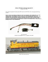
1. Introduction<br />
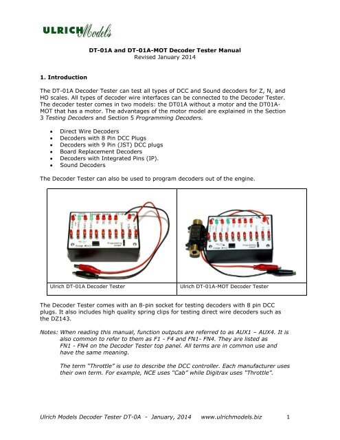
The <strong>DT</strong>-<strong>01</strong>A <strong>Decoder</strong> <strong>Tester</strong> can test all types of DCC and Sound decoders for Z, N, and<br />
HO scales. All types of decoder wire interfaces can be connected to the <strong>Decoder</strong> <strong>Tester</strong>.<br />
The decoder tester comes in two models: the <strong>DT</strong><strong>01</strong>A without a motor and the <strong>DT</strong><strong>01</strong>A-<br />
MOT that has a motor. The advantages of the motor model are explained in the Section<br />
3 Testing <strong>Decoder</strong>s and Section 5 Programming <strong>Decoder</strong>s.<br />
<br />
<br />
<br />
<br />
<br />
<br />
Direct Wire <strong>Decoder</strong>s<br />
<strong>Decoder</strong>s with 8 Pin DCC Plugs<br />
<strong>Decoder</strong>s with 9 Pin (JST) DCC plugs<br />
Board Replacement <strong>Decoder</strong>s<br />
<strong>Decoder</strong>s with Integrated Pins (IP).<br />
Sound <strong>Decoder</strong>s<br />
The <strong>Decoder</strong> <strong>Tester</strong> can also be used to program decoders out of the engine.<br />
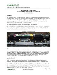
<strong>Ulrich</strong> <strong>DT</strong>-<strong>01</strong>A <strong>Decoder</strong> <strong>Tester</strong><br />
<strong>Ulrich</strong> <strong>DT</strong>-<strong>01</strong>A-MOT <strong>Decoder</strong> <strong>Tester</strong><br />
The <strong>Decoder</strong> <strong>Tester</strong> comes with an 8-pin socket for testing decoders with 8 pin DCC<br />
plugs. It also includes high quality spring clips for testing direct wire decoders such as<br />
the DZ143.<br />
Notes: When reading this manual, function outputs are referred to as AUX1 – AUX4. It is<br />
also common to refer to them as F1 - F4 and FN1- FN4. They are listed as<br />
FN1 - FN4 on the <strong>Decoder</strong> <strong>Tester</strong> top panel. All terms are in common use and<br />
have the same meaning.<br />
The term “Throttle” is use to describe the DCC controller. Each manufacturer uses<br />
their own term. For example, NCE uses “Cab” while Digitrax uses “Throttle”.<br />
<strong>Ulrich</strong> <strong>Models</strong> <strong>Decoder</strong> <strong>Tester</strong> <strong>DT</strong>-0A - January, 2<strong>01</strong>4 www.ulrichmodels.biz 1
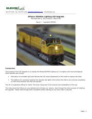
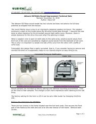
An inexpensive adapter harness is required to test decoders with 9 pin, DCC Quick<br />
Connect plugs (Also known as JST connectors).<br />
JST 9 Pin Adapter Harness<br />
Note: Any DCC wire harness with an eight pin plug and 9 pin JST connector will work.<br />
Our harness has some strain relief and the purple lead is 1” longer to aid in connection<br />
to the purple (F2) spring clip.<br />
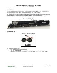
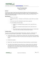
For Board Replacement (Drop-In) <strong>Decoder</strong>s, the easy attach, Clip Harness with spring<br />
clips is required.<br />
<strong>Decoder</strong> Clip Harness (pin 1 is marked with a red dot).<br />
2. <strong>Decoder</strong> <strong>Tester</strong> Basics<br />
DCC 8 pin Socket<br />
The <strong>Decoder</strong> <strong>Tester</strong> has an 8 pin DCC socket for testing decoders with 8 pin DCC<br />
connectors. <strong>Decoder</strong>s with an 8 pin DCC connector can be plugged directly into the<br />
tester socket. The socket is marked for proper connector insertion; pin 1 (orange<br />
lead) on the lower left corner.<br />
Track Power Clips<br />
The red and black alligator clips are for powering the <strong>Decoder</strong> <strong>Tester</strong>; one for the<br />
right rail and one for the left. There is no polarity requirement and the clips can be<br />
connected to either rail as long as both rails are connected.<br />
Always disconnect the power leads while connecting and disconnecting a<br />
decoder or turn DCC power off.<br />
<strong>Ulrich</strong> <strong>Models</strong> <strong>Decoder</strong> <strong>Tester</strong> <strong>DT</strong>-0A - January, 2<strong>01</strong>4 www.ulrichmodels.biz 2
Programming Jumper<br />
When the programming jumper is removed, a 120 ohm resistor is placed in series<br />
with track power. This limits the current to the decoder and is an extra measure<br />
protection. When this jumper is not installed, the LED indicators will be dimmer and<br />
there will be some dimming when multiple LEDs are on.<br />
As long as decoders are inserted correctly into the decoder DCC socket or wire leads<br />
are clipped to the correct test clip, there is little need to run with this jumper<br />
removed. However, when connecting a decoder with a wire harness to the spring<br />
clips or a board replacement decoder using the Clip Harness, it is prudent to remove<br />
the jumper until you are certain the decoder is correctly connected. The decoder can<br />
be tested completely with the jumper removed.<br />
The jumper is required to insure proper voltages when programming decoders. When<br />
removing the jumper, it can be slipped on one lead to prevent losing it.<br />
Spring Clips<br />
There are ten spring clips for connecting decoders with only a wire harness and no<br />
DCC plug. Each spring clip is labeled with the correct color for each decoder wire.<br />
These are very high quality spring clips and are very easy to use. They are one of<br />
the most expensive components of the <strong>Decoder</strong> <strong>Tester</strong>.<br />
LEDs<br />
There are nine LEDs in the tester which are used to indicate power, direction and<br />
function output activity. All LED indicators are designed for 12 volt decoder outputs<br />
and will not function if connected to regulated outputs designed for 1.5 volt lamps.<br />
Indicator List<br />
<br />
<br />
<br />
<br />
Pilot – Indicates track power is applied.<br />
Motor Forward and Reverse – These two LEDs indicate motor direction and<br />
speed. The higher the DCC speed step the brighter the LED. Since most<br />
motor decoders use some type of pulsing to enhance motor operation, the<br />
lights may flicker.<br />
Lamp Forward and Reverse – Indicates the status and brightness of the<br />
headlight and backup light. The headlight is usually activated by pressing F0<br />
on the throttle. The behavior of the lamps depends on various decoder<br />
settings such as brightness, on/off, and direction behavior settings.<br />
FN1 through FN4 – Indicates the status of the AUX1 through AUX4 function<br />
outputs.<br />
These outputs are normally activated by pressing function keys on the<br />
throttle. On non-sound decoders, the default assignments are usually<br />
F1 = AUX1, F2 = AUX2 and etc. However, sound decoders depend entirely on<br />
the default function key mapping and vary widely.<br />
<strong>Ulrich</strong> <strong>Models</strong> <strong>Decoder</strong> <strong>Tester</strong> <strong>DT</strong>-0A - January, 2<strong>01</strong>4 www.ulrichmodels.biz 3
The operation of AUX1 through AUX4 depends entirely on the internal function<br />
mapping of the decoder for both on/off and lighting effect operation. If these<br />
outputs do not behave as you expect, use the throttle to read the decoder’s<br />
mapping CVs to verify behavior. Resetting the decoder will set it back to its<br />
default mapping<br />
3. Testing DCC <strong>Decoder</strong>s<br />
This section covers testing decoders. See Topic 5: Programming <strong>Decoder</strong>s for<br />
information on programming decoders with the <strong>Decoder</strong> <strong>Tester</strong>.<br />
Most decoders are tested by connecting the decoder to the tester using the 8 pin<br />
socket, or the direct wire spring clips. The red and black alligator clips are clipped to<br />
DCC track power. <strong>Decoder</strong>s with a JST 9 pin connector require the JST Clip Harness<br />
and Board replacement decoders require the Clip Harness.<br />
For sound decoders, clip a speaker onto the audio output tabs or leads of the<br />
decoder to hear sound.<br />
General Procedure for Testing <strong>Decoder</strong>s<br />
The <strong>Decoder</strong> <strong>Tester</strong> basically simulates a locomotive for the decoder. You can<br />
actually think of the decoder tester as a locomotive that does not move. Just extend<br />
that idea to actually testing the decoder.<br />
Using your DCC Throttle or computer test station, send DCC commands to the<br />
decoder being tested just as you would when it is installed in a locomotive. The same<br />
rules apply; if you are in OPs mode, running the decoder, you must know the<br />
address the decoder is set to. For new decoders this is address 3.<br />
To test the motor circuit increase and decrease the throttle in forward and reverse<br />
and check the forward and reverse light. For lighting functions, turn the headlight on<br />
and off and activate the functions by pressing the function keys on your throttle.<br />
Remember, the decoder function mapping and lighting effects programming<br />
determine the behavior of the function keys in relation to function outputs.<br />
Note:<br />
Steam Sound decoders (except for Soundtraxx) use motor Back EMF to<br />
synchronize chuffs to 4 chuffs per revolution. These decoders will not run the<br />
motor or advance the sound if a motor is not connected to the decoder<br />
tester. When testing these decoders, a motor must be clipped to the two<br />
motor test points, spring clips on the decoder tester. Any decent motor can<br />
be used or see our <strong>DT</strong><strong>01</strong> Motor Upgrade Kit listed on the website P/N 4-<br />
<strong>DT</strong><strong>01</strong>-MU<br />
<strong>Ulrich</strong> <strong>Models</strong> <strong>Decoder</strong> <strong>Tester</strong> <strong>DT</strong>-0A - January, 2<strong>01</strong>4 www.ulrichmodels.biz 4
Testing 8 Pin <strong>Decoder</strong>s<br />
Testing a decoder with an 8 pin DCC connector is easy. Just plug it into the DCC<br />
socket with the orange lead (pin 1) at the lower left corner.<br />
All functions can be tested and programmed including motor forward and reverse,<br />
headlight, backup light and AUX1. If the decoder has additional AUX outputs,<br />
connect the wire leads to the proper spring clip. The spring clip has the color of the<br />
wire for the proper AUX output listed above it.<br />
Testing Direct Wire <strong>Decoder</strong>s<br />
<strong>Ulrich</strong> <strong>Models</strong> <strong>Decoder</strong> <strong>Tester</strong> <strong>DT</strong>-0A - January, 2<strong>01</strong>4 www.ulrichmodels.biz 5
<strong>Decoder</strong>s built for direct wire interfacing such as the DZ123 are easy to test with the<br />
<strong>Decoder</strong> <strong>Tester</strong>. Connect the wires directly to the spring clips. Each spring clip is<br />
labeled by wire color.<br />
The wires used with decoders are usually 30 gauge and have a very small diameter.<br />
When inserting the wire under the clips, it is sometimes necessary to move it to the<br />
back to insure holding pressure.<br />
Testing JST 9 Pin <strong>Decoder</strong>s<br />
The 9 pin connectors used as an integrated part of these decoders are often referred<br />
to as 9 pin easy connect or 9 pin JST connectors. JST is the manufacturer of these<br />
type connectors.<br />
The JST 9 pin connectors support track voltage, motor, headlight, backup light, AUX1<br />
and AUX2 in the connector. This gives greater flexibility than the 8 pin DCC<br />
connector. They plug directly into Athearn, Proto and many other locomotives. They<br />
often come with a direct wire harness for installation in locomotives without a DCC<br />
connector.<br />
To test these decoders, use the optional 9 Pin JST harness. Connect the extra purple<br />
lead wire to the purple lead spring clip on the decoder (FN2).<br />
<strong>Ulrich</strong> <strong>Models</strong> <strong>Decoder</strong> <strong>Tester</strong> <strong>DT</strong>-0A - January, 2<strong>01</strong>4 www.ulrichmodels.biz 6
Connections made with JST connectors are often very tight and sometimes are<br />
difficult to separate. When removing the decoder from the JST harness, do so<br />
carefully to prevent damage to the harness. If the harness is damaged, contact us<br />
for a replacement. There is no shipping fee. Only the nominal cost for the harness<br />
itself.<br />
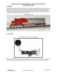
Testing Board Replacement <strong>Decoder</strong>s<br />
Testing a Digitrax DH165A0 Board Replacement <strong>Decoder</strong><br />
Board replacement decoders are among the more complicated decoders to test. They<br />
require using the Clip Harness and their function outputs have varied capabilities. To<br />
insure proper alignment of the Clip Harness into the decoder socket, pin 1 is marked<br />
with a red dot. Line the dot up with the pin 1 indicator on the tester.<br />
The Digitrax DH165, Athearn replacement decoder has regulated lamp outputs that<br />
will not drive the lamp LEDs in the tester; the LED indicator circuits are designed for<br />
12 volt outputs. The motor circuit can be connected and tested but the lamp circuit,<br />
in this case, is tested by connecting a 1.5 volt lamp across the F0F and F0F+<br />
outputs. The same holds true for the F0R and F0R+ outputs.<br />
Another way to test the lamp circuits is to connect the white and blue leads to the FO<br />
and FO+ decoder tabs, The 1.5 volt lamp is then clipped across the white (headlight)<br />
and blue (common) spring clips. A similar procedure works for the reverse lamp.<br />
Other board replacement decoders such as the SDH104K1A or DN163K2 have the<br />
forward and reverse light LEDs mounted right on the board and testing the lamp<br />
circuits is easy with no lamp clips required.<br />
Watch for application notes posted on the <strong>Ulrich</strong> <strong>Models</strong> web site to aid in testing the<br />
more complicated decoders.<br />
<strong>Ulrich</strong> <strong>Models</strong> <strong>Decoder</strong> <strong>Tester</strong> <strong>DT</strong>-0A - January, 2<strong>01</strong>4 www.ulrichmodels.biz 7
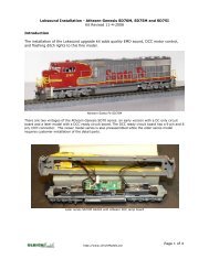
Testing Sound <strong>Decoder</strong>s<br />
Sound decoders with an attached speaker can be tested and programmed using the<br />
<strong>Decoder</strong> <strong>Tester</strong>. A LokSound decoder is shown here. The LED motor circuit works<br />
correctly with most motor decoders so you can listen to the sounds at all engine<br />
speeds.<br />
When testing sound decoders, remember that most function keys are mapped to<br />
sounds and it may be necessary to remap the keys to test AUX1-AUX4. The<br />
headlight and backup light are normally mapped to the F0 function key.<br />
The LokSound programmer can be interfaced directly to the <strong>Decoder</strong> <strong>Tester</strong> by<br />
attaching the track leads to the two track power spring clips. Make sure the decoder<br />
programming jumper is installed.<br />
4. Programming <strong>Decoder</strong>s<br />
Programming in OPs mode<br />
Programming in OPs mode is just like programming your locomotive on the track.<br />
Select the address of the decoder on your throttle, enter ops mode programming and<br />
program the decoder. You can even set the decoder address.<br />
Programming in Program Track Mode<br />
When using program track mode, you must have a motor connected to the decoder<br />
tester. DCC decoders use the motor to create DCC protocol signals that can be read<br />
by the receiving DCC device. Without the motor, your throttle will report no response.<br />
<strong>Ulrich</strong> <strong>Models</strong> <strong>Decoder</strong> <strong>Tester</strong> <strong>DT</strong>-0A - January, 2<strong>01</strong>4 www.ulrichmodels.biz 8
Testing decoders in program track mode is easy. The setup is exactly the same only<br />
clip the <strong>Decoder</strong> tester input leads to the program track rails or outputs. Next enter<br />
Program Track mode, either Page or Direct mode as appropriate. Most programming<br />
is done in Page Mode. Now you can program or read CVs. The exception to this is the<br />
Digitrax Empire Builder Starter System; It cannot read CVS because it uses a DCS50<br />
instead of a DCS100.<br />
5. Warranty<br />
The decoder tester is warranted for one year and will be repaired or replaced free of<br />
charge if it malfunctions. The one-year warranty does not include the Clip Harness<br />
or the JST Harness. These are more fragile and are subject to wear from use. The<br />
JST Harness is inexpensive to replace. The Clip Harness is inexpensive to repair.<br />
There is no return shipping fee for one year on these items (applies to domestic<br />
shipping only). After one year, there is a nominal shipping fee for 1 st class mail. If we<br />
ship you a defective harness, it will be replaced free.<br />
<strong>Ulrich</strong> <strong>Models</strong> <strong>Decoder</strong> <strong>Tester</strong> <strong>DT</strong>-0A - January, 2<strong>01</strong>4 www.ulrichmodels.biz 9