Athearn Gas Turbine LED Lighting Upgrade Kit ... - Ulrich Models
Athearn Gas Turbine LED Lighting Upgrade Kit ... - Ulrich Models
Athearn Gas Turbine LED Lighting Upgrade Kit ... - Ulrich Models
- No tags were found...

You also want an ePaper? Increase the reach of your titles
YUMPU automatically turns print PDFs into web optimized ePapers that Google loves.
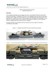
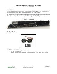
<strong>Kit</strong> DesignFigure 2 - <strong>LED</strong> <strong>Upgrade</strong> <strong>Kit</strong>The kit is designed to plug into the 8-pin DCC connector for ease of installation. The 8-pinconnector is in parallel with the 9-pin connector and is available since the decoder installsinto the 9-pin JST connector. This kit bypasses the <strong>Athearn</strong> lighting boards for headlight,reverse light and Mars light.On the end of each lead is a miniature surface mount <strong>LED</strong> glued to a 1.5 mm fiber optictube. The tube slides into each light mount in place of the bulb. The reverse light and Marslight <strong>LED</strong>s shine through the light tubes into the turbine lenses in the shell. The headlight<strong>LED</strong> is mounted on the front of the light tube pointing out. It is installed with the <strong>LED</strong>pointing directly toward the headlight lens openings in the shell. This is required since theheadlight mount is positioned between the two headlight lenses. Note that the bulbmounting holes are 1.4 mm and the light tubes are 1.5 mm. The mounting holes do requirea little reaming; this is covered in the installation portion of the document.InstallationThis kit is easy to install; however, care must be exercised due to the fragile components.Rough handling of the <strong>LED</strong>s/light tube assembly can result in separation of the <strong>LED</strong> fromthe tube. Care has been taken in manufacturing to provide a sturdy bond but it is possiblefor the <strong>LED</strong> to become unattached. If this happens, we will exchange the kit.Note: The <strong>Athearn</strong> circuit board has a short between the headlight and Function 4.You must clip the purple wire from the 9-pin connector to the circuit board.It can be clipped right at the board. The wire can be taped to the decoderlater or you can cut it off entirely.http://www.<strong>Ulrich</strong><strong>Models</strong>.biz2
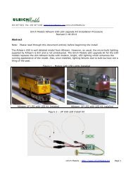
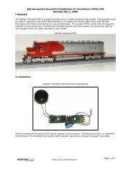
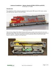
This kit is designed for the decoder programming that is loaded into the QSI decoder sold by<strong>Ulrich</strong> <strong>Models</strong>. If you are using a decoder purchased from another source, the decoder mustbe reprogrammed or a wiring change is required. See Appendix 1 at the end of thisdocument for the wiring change. If you send the decoder to us, we will reprogram it free.If you have a Quantum Programmer, we can send you our turbine file.Figure 3 – <strong>Gas</strong> <strong>Turbine</strong> as Delivered – Shell OffFrontRearInstallation Steps1. Remove the shell and tape.The shell is held on by four screws located under the front and rear trucks. Once thescrews are removed, the shell slips off easily.Remove the two pieces of tape that run across the narrow width of the frame. Also,unwrap the tape that goes around the rear circuit board. Be careful, there are lots ofwires underneath. Cutters are not recommended.2. Remove the headlight and Mars light bulbs.Slide the light bulbs out of the front light bulb mount. Pull the bulbs through thetape that wraps around the front circuit board. Lift the tape along the side of themotor cover to release the wires; pull the clips off the circuit board tabs and removethe two wires. There is no need to put the wire clips back on.http://www.<strong>Ulrich</strong><strong>Models</strong>.biz3
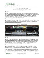
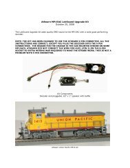
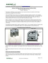
3. Remove the backup light bulbRemove the bulb from the rear light mount. Remove the clips from the two tabs thewires are connected to. Remove the wires.There are two additional wires on these tabs that are grey. The wires must bereinserted into the tabs and the clips put back on. It does not matter which wiregoes in which tab. These wires are for the tender light.Figure 4 – Rear Section with tape removed.4. Install the Light <strong>Kit</strong> ConnectorThe sound kit can be installed now if it has not been installed previously. Do notinstall the decoder at this time or remove it if installed already.Plug in the 8-pin connector for the kit. Pin 1 is marked on the circuit board and isshown in Figure 4. The yellow wire (backup light) is connected to pin 2 and will beone hole over from the marked pin 1.http://www.<strong>Ulrich</strong><strong>Models</strong>.biz4
5. Install the headlight and MARS light <strong>LED</strong>sFigure 5 - Front headlight installationRemove the headlight / Mars light mount assembly from the frame by removing thetwo screws. Take a #53 drill bit in a pin vise and gently use it to increase the size ofthe headlight and Mars holes. It does not take much so don’t be too aggressive.The Mars light hole is the top hole and the headlight hole is the bottom hole. Test thehole size with the extra piece of light tube included in the kit.Insert the headlight into the lower hole as shown. The headlight is attached to thewhite wire. Insert the headlight from the front. Be careful to not dislodge the <strong>LED</strong>from the light tube. You can use a pair of needle nose pliers to carefully insert thetube and then push it in with your fingers. If the orientation is not correct, it can berotated from the backside with the pliers or tweezers after it is installed.Note: The <strong>LED</strong> light pattern is not always the same. If the two headlight lenses arenot evenly lighted, remove the shell and rotate the <strong>LED</strong> 90 degrees to vertical.Some trial and error may be required to find the best angle for the <strong>LED</strong>.Insert the Mars light into the top hole as shown. The Mars light is connected to thegreen wire.Placing a small piece of tape over the wires and taping them to the flat part of theheadlight mount assembly will help to secure the installation.Reinstall the headlight mount.Route the wires back over the motor shield and under the tape on one side. Thereare three resistors in the wires. Place them far enough apart so they lay flat on theshield. If you have installed the sound kit already, you can apply a piece of tapeacross the frame to help secure the wiring. The wires can also be run down thecenter of the plastic motor cover and taped.http://www.<strong>Ulrich</strong><strong>Models</strong>.biz5
Figure 6 - Headlight and Mars light installed with the sound kit.6. Install the backup <strong>LED</strong>.Gently use the #53 drill in a pin vise to expand the backup light mounting hole. Testthe backup light mounting hole size with the spare fiber optic tube beforeproceeding. Using a fine tip pair of needle nose pliers, insert the backup light tubeinto the rear lamp mount as shown. Position the resistors so they lie as flat aspossible.Slip a piece of tape around the resistors and wire bundle to secure the resistors andwire bundle. This tape replaces the original tape that was removed.Figure 7 – <strong>LED</strong> Installation – <strong>Turbine</strong> Rearhttp://www.<strong>Ulrich</strong><strong>Models</strong>.biz6
7. Complete the installationPlace a small piece of black tape over the Mars light and backup light to preventstray light from entering the shell.Install the QSI Decoder and connect the speaker wire. The decoder is positionedwith the connectors down to increase clearance. The decoder is held in place bywrapping a piece of electrical tape around the circuit board and decoder. Be sure theJST connector housing on the decoder is not in a direct line with the shell mountingholes.The two plastic mounting posts in the shell must slip over the decoder whenreinstalling the shell; tilting the decoder to one side will give help to clear the posts.Once the decoder is taped down, plug the speaker connector together.Be sure that all wires are inside the shell mounting holes in the frame; any wiresoutside of the holes will be caught and crushed during the shell reinstall.Next put the shell back on. When sliding the shell down over the frame andcomponents, be sure all wires are clear and do not get caught between the shell andthe frame. When the posts come in contact with the decoder, use your fingers toslightly expand the shell to help it slide over the decoder. This is tight fit but there isno other way to accomplish this.Test the locomotive before installing the four screws.Reinstall the four screws. The locomotive is now ready to go.F12 turns on the Mars Light.Figure 8 - Completed InstallTender <strong>Lighting</strong>There is a 51 Ohm resistor in the light kit. This replaces the resistor that <strong>Athearn</strong> installedin the tender to increase the tender backup light intensity.Remove the tender shell by removing the 4 screws in the bottom frame.Remove the bulb from the backup light.Remove the shrink wrapped resistor by cutting it outReplace the resistor with the 51 Ohm resistor and new shrink wrap.Reassemble the tenderhttp://www.<strong>Ulrich</strong><strong>Models</strong>.biz7
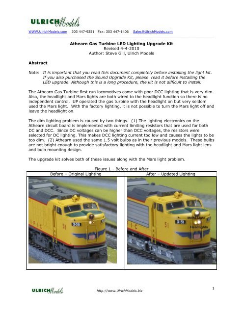
8. Headlight Notes.The design of the factory headlights for the gas turbine model is quite poor. There isa single 1.4 mm bulb mount pointing at the two headlight fiber optics. The headlightopenings in the shell are located to the right and left of the bulb mount on the frame.This is not a good design. There should have been a bulb for each headlight opticwith direct alignment to its respective fiber optic tube or a more sophisticated fiberoptic design used. Furthermore, incandescent bulbs should not have been used inthis model; <strong>LED</strong>s are required due to their greater brightness.To compensate for the headlight design flaw, the kit uses a high intensity miniature<strong>LED</strong> mounted on the front of a fiber optic tube. Miniature <strong>LED</strong>s have a wide lightspread and are not directional like the 3 mm <strong>LED</strong>s. Mounting the <strong>LED</strong> pointing at theholes offered the best light spread to support light entering both of the headlightoptic tubes. Mounting the <strong>LED</strong> to the rear of the tube would make the light beam tonarrow.Unfortunately, the turbine manufacturer was very sloppy with the installation of theheadlight optic tubes. On some turbines, the optic tubes do not reach all the way tothe back of the shell. On these models, it may be necessary to use the #53 drill toenlarge the backside of the headlight holes in the shell. I encountered one modelwhere the fiber optic tubes were either not installed or had fallen out. I had to insertnew Details West lenses in to make the headlights work properly. Check your lensescarefully; they may be loose and could fall out.If there are headlight difficulties after installing the kit, some tweaking may berequired due to the above issues.Appendix 1 - Wiring Change for decoders purchased from other dealers.Our decoders are programmed for the rear Mars light on function output 3 and the frontMars Light on output 5. The standard QSI turbine file has the Mars light on output 5 only.We added Port 3 for the rear Mars light to allow the 8-pin DCC connector to be used for thekit install. There is not a function 5 output on the 8-pin connector. The front and rear Marslight outputs are both programmed to operate when F12 is pressed.To move the Mars light to output 5 for other decoders, the green wire from the 8-pinconnector must be removed and then connected to the green-stripe wire from the rearRevolution decoder (P2) connector.http://www.<strong>Ulrich</strong><strong>Models</strong>.biz8