Installation of Loksound decoder in Athearn SD70M - Ulrich Models
Installation of Loksound decoder in Athearn SD70M - Ulrich Models
Installation of Loksound decoder in Athearn SD70M - Ulrich Models

Create successful ePaper yourself
Turn your PDF publications into a flip-book with our unique Google optimized e-Paper software.
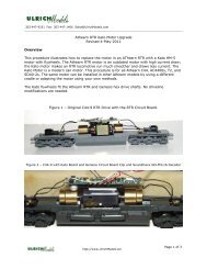
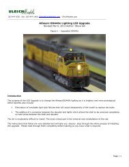
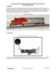
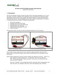
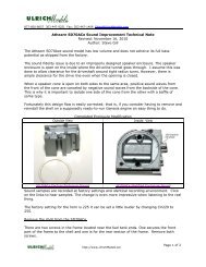
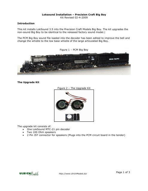
<strong>Loksound</strong> <strong>Installation</strong> – Precision Craft Big BoyKit Revised 02-4-2009IntroductionThis kit <strong>in</strong>stalls LokSound 3.5 <strong>in</strong>to the Precision Craft <strong>Models</strong> Big Boy. The kit upgrades thenon-sound Big Boy to be identical to the released factory sound model.|The PCM Big Boy sound file loaded <strong>in</strong>to the <strong>decoder</strong> has been edited to improve the bell andchange the whistle to the low base whistle <strong>of</strong> the large articulated Big Boy.Figure 1 – PCM Big BoyThe Upgrade KitFigure 2 – The Upgrade KitThe upgrade kit consists <strong>of</strong>:• One LokSound MTC-21 p<strong>in</strong> <strong>decoder</strong>• Two 100 Ohm speakers• 2 P<strong>in</strong> JST connector for speakers (Plugs <strong>in</strong>to the PCM circuit board <strong>in</strong> the tender)http://www.<strong>Ulrich</strong><strong>Models</strong>.bizPage 1 <strong>of</strong> 3
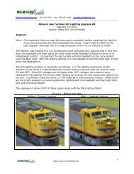
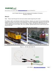
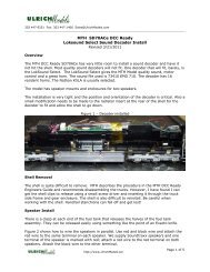
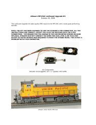
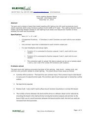
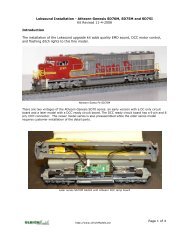
<strong>Installation</strong>Figure 3 - Installed Kit1. Remove the tender shell by remov<strong>in</strong>g the 4 screws located at the four corners <strong>of</strong> thetender floor. Remove the rear coupler and lift the tender shell <strong>of</strong>f the frame.2. Un<strong>in</strong>stall the smoke unit jumper located on the circuit board. Remov<strong>in</strong>g the jumperwill disable the manual DC smoke switch and enable <strong>decoder</strong> control <strong>of</strong> the smokeunit. The jumper can be left attached to one p<strong>in</strong> or totally removed.3. Remove the circuit board from the mount by unscrew<strong>in</strong>g the mount<strong>in</strong>g screw locatedat lower left corner <strong>of</strong> the board. It also holds the smoke switch panel. Move theboard aside, it will still be connected to the harness and backup light.4. Remove the speaker reta<strong>in</strong><strong>in</strong>g frame, located under the circuit board, by unscrew<strong>in</strong>gthe two screws located <strong>in</strong> the center <strong>of</strong> the frame.5. Place the two speakers from the kit <strong>in</strong> their mounts as shown <strong>in</strong> Figure 4. Run thewires connect<strong>in</strong>g the two speakers as shown to avoid p<strong>in</strong>ch<strong>in</strong>g them between thespeaker and the frame.Figure 4 – Speaker Placement6. Re<strong>in</strong>stall the frame. Run the speaker wire with the connector up through the slot <strong>in</strong>the middle <strong>of</strong> the speaker reta<strong>in</strong><strong>in</strong>g frame.http://www.<strong>Ulrich</strong><strong>Models</strong>.bizPage 2 <strong>of</strong> 3
Figure 5 – Speaker and Reta<strong>in</strong><strong>in</strong>g Frame <strong>Installation</strong>7. Re<strong>in</strong>stall the circuit board and connect the JST 2 p<strong>in</strong> connector to the open headeron the board. See figure 3.8. Install the 21 p<strong>in</strong> MTC <strong>Loksound</strong> <strong>decoder</strong>. When you <strong>in</strong>stall the <strong>decoder</strong>, you mayneed to reposition the large capacitor and flatten the leads. Be sure any barecapacitor leads do not touch each or the <strong>decoder</strong>. Install the <strong>decoder</strong> with the blackconnector up. It is keyed to prevent improper <strong>in</strong>stallation. Figure 3 shows thecorrect <strong>in</strong>stallation9. Re<strong>in</strong>stall the tender shell and test the locomotive.http://www.<strong>Ulrich</strong><strong>Models</strong>.bizPage 3 <strong>of</strong> 3