QSI Revolution Sound Kit Installation for the Athearn ... - Ulrich Models
QSI Revolution Sound Kit Installation for the Athearn ... - Ulrich Models
QSI Revolution Sound Kit Installation for the Athearn ... - Ulrich Models

Create successful ePaper yourself
Turn your PDF publications into a flip-book with our unique Google optimized e-Paper software.
<strong>QSI</strong> <strong>Revolution</strong> <strong>Sound</strong> <strong>Kit</strong> <strong>Installation</strong> <strong>for</strong> <strong>the</strong> A<strong>the</strong>arn FP45/F45<br />
Revised July 3, 2009<br />
I Abstract<br />
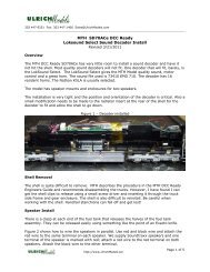
The A<strong>the</strong>arn Genesis FP45 is a great locomotive but it needs a great sound system. This procedure can<br />
be used to upgrade a non-sound FP45 Genesis or to replace <strong>the</strong> factory MRC sound with <strong>the</strong> <strong>QSI</strong><br />
<strong>Revolution</strong>, <strong>the</strong> latest improvement in sound technology. The sound of FP45 model with <strong>the</strong> upgrade<br />
installed is very impressive. Fur<strong>the</strong>rmore, <strong>the</strong> <strong>QSI</strong> decoder has more options <strong>for</strong> controlling lighting<br />
and operation than any o<strong>the</strong>r decoder on <strong>the</strong> market.<br />
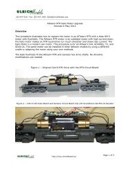
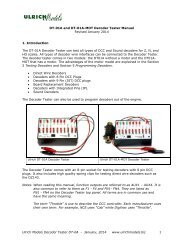
A<strong>the</strong>arn Genesis FP45<br />
II <strong>Installation</strong><br />
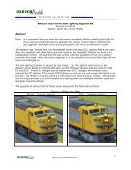
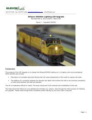
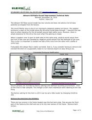
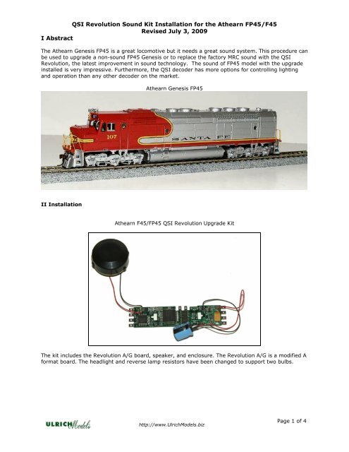
A<strong>the</strong>arn F45/FP45 <strong>QSI</strong> <strong>Revolution</strong> Upgrade <strong>Kit</strong><br />
The kit includes <strong>the</strong> <strong>Revolution</strong> A/G board, speaker, and enclosure. The <strong>Revolution</strong> A/G is a modified A<br />
<strong>for</strong>mat board. The headlight and reverse lamp resistors have been changed to support two bulbs.<br />
http://www.<strong>Ulrich</strong><strong>Models</strong>.biz<br />
Page 1 of 4
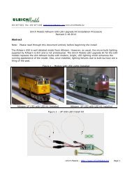
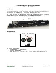
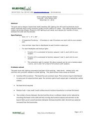
FP45 with <strong>Kit</strong> Installed<br />
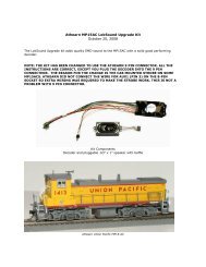
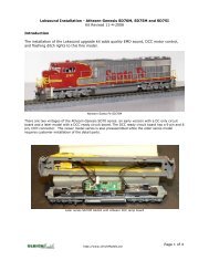
<strong>Revolution</strong> Board Diagram<br />
1. Remove <strong>the</strong> shell of <strong>the</strong> locomotive by first removing <strong>the</strong> couplers. Then remove <strong>the</strong><br />
two screws in <strong>the</strong> bottom of <strong>the</strong> frame that hold <strong>the</strong> shell. There is one screw under<br />
each truck. The frame will <strong>the</strong>n slide off easily.<br />
2. Disconnect <strong>the</strong> wires going to <strong>the</strong> Genesis lamp board and <strong>the</strong>n unclip <strong>the</strong> board from <strong>the</strong><br />
motor clips.<br />
3. Install <strong>the</strong> <strong>Revolution</strong> in place of <strong>the</strong> Genesis lamp board. Be sure <strong>the</strong> front of <strong>the</strong> board is<br />
toward <strong>the</strong> cab. The cap is attached to <strong>the</strong> front and <strong>the</strong> speaker pads are located to <strong>the</strong> rear.<br />
We recommend replacing <strong>the</strong> A<strong>the</strong>arn light bulbs with new 1.5 volt 13-15 mA lamps. A<strong>the</strong>an<br />
bulbs are not high quality and <strong>the</strong>ir life is unpredictable.<br />
http://www.<strong>Ulrich</strong><strong>Models</strong>.biz<br />
Page 2 of 4
4. Connect <strong>the</strong> two front headlight bulbs. Connect <strong>the</strong> bulbs in parallel with each o<strong>the</strong>r. Twist<br />
one lead from each bulb toge<strong>the</strong>r, tin <strong>the</strong>m, and <strong>the</strong>n solder <strong>the</strong> leads to <strong>the</strong> +5V tab. Twist<br />
<strong>the</strong> o<strong>the</strong>r two leads toge<strong>the</strong>r, tin <strong>the</strong> leads and solder <strong>the</strong>m to <strong>the</strong> F0-F tab.<br />
It is recommended that you solder <strong>the</strong> leads to <strong>the</strong> <strong>Revolution</strong> tabs and do not use <strong>the</strong><br />
A<strong>the</strong>arn retaining caps.<br />
5. The two reverse lamps will also be connected in parallel. Locate one lead from each lamp and<br />
solder <strong>the</strong>m toge<strong>the</strong>r. Twist one lead from each bulb toge<strong>the</strong>r, tin <strong>the</strong>m, and <strong>the</strong>n solder <strong>the</strong><br />
leads to <strong>the</strong> +5V tab. Twist <strong>the</strong> o<strong>the</strong>r two leads toge<strong>the</strong>r, tin <strong>the</strong> leads and solder <strong>the</strong>m to <strong>the</strong><br />
F0-R tab.<br />
6. Connect one lead of <strong>the</strong> light located above <strong>the</strong> cab to <strong>the</strong> F5 solder pad. Solder <strong>the</strong> remaining<br />
wire to one of <strong>the</strong> +5 V tabs.<br />
7. Attach <strong>the</strong> speaker, as shown in <strong>the</strong> <strong>Kit</strong> Installed picture, with some E6000 or Goop adhesive<br />
applied where <strong>the</strong> speaker contacts <strong>the</strong> frame. The speaker fits perfectly into <strong>the</strong> round recess<br />
where <strong>the</strong> speaker contacts <strong>the</strong> frame.<br />
8. Solder <strong>the</strong> motor leads to <strong>the</strong> motor tab with black lead soldered to <strong>the</strong> front tab (-).<br />
9. Attach <strong>the</strong> capacitor to <strong>the</strong> side of <strong>the</strong> frame with <strong>the</strong> same adhesive.<br />
10. Place <strong>the</strong> shell on frame and test be<strong>for</strong>e final reassembly.<br />
III <strong>Revolution</strong> Programming<br />
The <strong>Revolution</strong> board is loaded with sound file 292-0 EMD 645 with <strong>the</strong> high bass engine sound and<br />
Nathan M5, 5 chime horn. O<strong>the</strong>r horns and files are available, contact us by email or phone <strong>for</strong> any<br />
fur<strong>the</strong>r sound customization.<br />
Forward and reverse lights are set to rule 17.<br />
Later FP45s do not have a Mars light so this paragraph can be ignored if you are updating a later<br />
FP45. F45s do not have Mars Lights. They often have a Overhead Beacon Light (OHBL) mounted on<br />
top of <strong>the</strong> cab.<br />
Mars Light – FP45<br />
Depending on <strong>the</strong> configuration of your FP45, <strong>the</strong>re can be one or two bulbs in <strong>the</strong> Mars Light. One of<br />
<strong>the</strong>m should be red if <strong>the</strong>re are two bulbs. On A<strong>the</strong>arn non- MRC sound models, <strong>the</strong> red bulb was left<br />
out. It can be added using a 15 mA 1.4 mm red bulb. The clear mars light should be connected to<br />
F5 and <strong>the</strong> red to F3. Function Key F10 will turn on <strong>the</strong> clear bulb and F12 will turn on <strong>the</strong> red.<br />
Strobe Light - F45<br />
Connect <strong>the</strong> Strobe light to Output F4. It is set to strobe light. Use F10 to turn it on or off.<br />
Default Configuration<br />
The CV configuration as shipped is stored as <strong>the</strong> decoder default. If you reset <strong>the</strong> decoder, all <strong>the</strong> CVs<br />
are restored to <strong>the</strong> default configuration <strong>for</strong> this specific locomotive. The decoder will be reset to <strong>the</strong><br />
default locomotive address. This will be address 3 <strong>for</strong> an uninstalled kit or <strong>the</strong> locomotive number if we<br />
installed <strong>the</strong> sound.<br />
http://www.<strong>Ulrich</strong><strong>Models</strong>.biz<br />
Page 3 of 4
IV <strong>Revolution</strong> Lamp Outputs<br />
The function outputs on <strong>the</strong> <strong>QSI</strong> <strong>Revolution</strong> are preconfigured <strong>for</strong> automatic lighting control as<br />
Follows:<br />
FL – Headlight on with Rule 17 Forward (On <strong>for</strong>ward, dim stopped or reverse)<br />
FR – Backup light - On in Reverse / Dim in Forward<br />
Output 3 – Rear Mars (second Mars Light)<br />
Output 4 – Cab Light - Can be used <strong>for</strong> number boards also.<br />
Output 5 – Front Mars Light<br />
Output 6 – Front Overhead Beacon Light (OHBL)<br />
V Function Assignments<br />
The <strong>Revolution</strong> function key assignments are as follows:<br />
F0 Headlight F4 Cooling fans F8 Mute<br />
F1 Bell F5 Dynamic brakes F9 Standby and Shutdown<br />
F2 Horn F6 Startup / Doppler F10 Front Mars Light and OHBL (Strobe)<br />
F3 Coupler clash F7 Long air/ Brake squeal F11 Horn Toggle Primary/Secondary<br />
F12 Mars Light 2<br />
http://www.<strong>Ulrich</strong><strong>Models</strong>.biz<br />
Page 4 of 4