MTH SD70ACe DCC Ready Loksound Select Sound ... - Ulrich Models
MTH SD70ACe DCC Ready Loksound Select Sound ... - Ulrich Models
MTH SD70ACe DCC Ready Loksound Select Sound ... - Ulrich Models
- No tags were found...

Create successful ePaper yourself
Turn your PDF publications into a flip-book with our unique Google optimized e-Paper software.
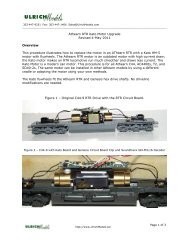
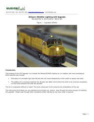
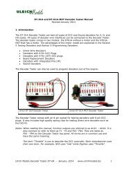
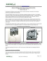
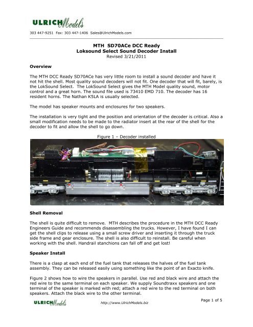
303 447-9251 Fax: 303 447-1406 Sales@<strong>Ulrich</strong><strong>Models</strong>.com____________________________________________________________________________________________Overview<strong>MTH</strong> <strong>SD70ACe</strong> <strong>DCC</strong> <strong>Ready</strong><strong>Loksound</strong> <strong>Select</strong> <strong>Sound</strong> Decoder InstallRevised 3/21/2011The <strong>MTH</strong> <strong>DCC</strong> <strong>Ready</strong> <strong>SD70ACe</strong> has very little room to install a sound decoder and have itnot hit the shell. Most quality sound decoders will not fit. One decoder that will fit, barely, isthe Lok<strong>Sound</strong> <strong>Select</strong>. The Lok<strong>Sound</strong> <strong>Select</strong> gives the <strong>MTH</strong> Model quality sound, motorcontrol and a great horn. The sound file used is 73410 EMD 710. The decoder has 16resident horns. The Nathan K5LA is usually selected.The model has speaker mounts and enclosures for two speakers.The installation is very tight and the position and orientation of the decoder is critical. Also asmall modification needs to be made to the radiator insert at the rear of the shell for thedecoder to fit and allow the shell to go down.Figure 1 – Decoder installedShell RemovalThe shell is quite difficult to remove. <strong>MTH</strong> describes the procedure in the <strong>MTH</strong> <strong>DCC</strong> <strong>Ready</strong>Engineers Guide and recommends disassembling the trucks. However, I have found I canget the shell clips to release using a small screw driver and inserting it through the truckside frame and gear enclosure. The shell is also difficult to reinstall. Be careful whenworking with the shell. Handrail stanchions can fall off and get lost!Speaker InstallThere is a clasp at each end of the fuel tank that releases the halves of the fuel tankassembly. They can be released easily using something like the point of an Exacto knife.Figure 2 shows how to wire the speakers in parallel. Use red and black wire and attach thered wire to the same terminal on each speaker. We supply <strong>Sound</strong>traxx speakers and oneterminal of the speaker is marked with red; attach a red wire to the red terminal on bothspeakers. Attach the black wire to the other terminal.http://www.<strong>Ulrich</strong><strong>Models</strong>.bizPage 1 of 5
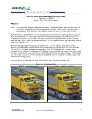
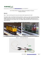
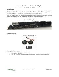
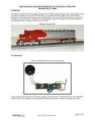
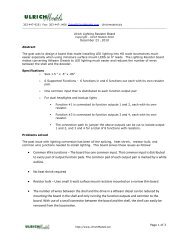
Figure 2 – Parallel Speaker WiringThe speakers are then installed into the enclosures using the 1” gaskets provided. Thespeaker enclosure covers are set on top of the enclosures with the wires run through theholes provided. The lids do not seal well and are prone to vibrating so they should beattached with a spot or two of glue or by placing some electrical tape on the tope cover tomake them fit tighter in the tank assembly when it is reinstalled.The wires are run up through the openings near the flywheel as shown in Figure 3. Whenthe speakers are connected to the decoder, the two reds are connected together and thetwo blacks are connected together.http://www.<strong>Ulrich</strong><strong>Models</strong>.bizPage 2 of 5
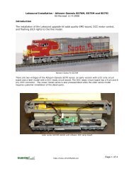
Figure 3 – Speaker Wiring, Speakers Installed in Tank.Decoder InstallationFigure 1 and Figure 4 show the decoder installed in the model. This installation is forLok<strong>Sound</strong> sound file 73410-<strong>MTH</strong>. The only difference between the normal 73410 file and the<strong>MTH</strong> file is the programming for the function outputs. The ditch lights have been movedfrom AUX1 and AUX2 to AUX 3 and 4 so the green wire does not have to be removed fromthe 8-pin socket to be connected to a ditch light tab. The number board has also beenprogrammed to AUX2 (green)Figure 4 – Decoder InstalledBefore installing the decoder, remove the <strong>MTH</strong> jumpers for the ditch lights and numberboards. Connect the purple wire from the front decoder connector (AUX2) to the numberboards. Connect the pink wire from the rear decoder connector to one of the ditch light tabsand the turquoise wire to the other ditch light tab. It is best to solder the wires as therubber caps do not work well and you may end up with a bad contact.Plug the 8-pin male connector into the 8-pin socket on the board.http://www.<strong>Ulrich</strong><strong>Models</strong>.bizPage 3 of 5
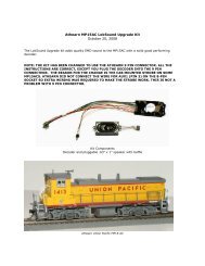
Place the decoder in the position shown in the picture with the 8-pin JST connector on thebottom. To position the board, slide it part way into the metal housing as shown.Use a thin tape, such has Kapton tape, to hold the decoder in place.Connect the speaker leads to the decoder. Connect both red leads to one brown speakeroutput wire and both black leads to the other brown speaker output wire. The brown wirescan be shortened if desired. The picture shows a two pin mini-connector being used for thespeaker connection. With or without a connector, some heat shrink tubing is required toinsulate the connection.The locomotive, minus the shell can be put on the track for testing. Unless the decoder hasbeen reprogrammed, F8 turns on the sound. F6 turns on the ditch lights and F5 turns on thenumber board lights.ReassemblyBefore putting the shell back on, remove the rear radiator cover. There are two vertical tabcatches on the shell were the radiator cover go that have be removed. They stick down andhit the decoder. The corresponding two tabs on the cover also must be removed. The coverwill fit snugly with the tabs removed. It is held by tabs in the back and friction in the front.It is unfortunate to have to make this modification but there is very little room in thismodel. I tried to position the decoder other places but was unable to get the shell down.Figure 5 – Radiator CoverFigure 6 Radiator Tabs To Removehttp://www.<strong>Ulrich</strong><strong>Models</strong>.bizPage 4 of 5
Next put the shell back on; it is quite difficult to do. To get the front of the shell down wherethe cab is, there are extrusions the must be aligned properly to slide into the frame section.The tabs on the shell must also be aligned. The shell will go down though. I thinkeverybody ought to write to <strong>MTH</strong> and ask them what the heck they were thinking when theydesigned the <strong>DCC</strong> ready model. It is a nice model but the lack of space is just ridiculous.Once the shell is on, place the radiator cover back on. Hopefully, you will never have to takeit apart again.http://www.<strong>Ulrich</strong><strong>Models</strong>.bizPage 5 of 5