Athearn DDA40x Lighting LED Upgrade - Ulrich Models
Athearn DDA40x Lighting LED Upgrade - Ulrich Models
Athearn DDA40x Lighting LED Upgrade - Ulrich Models
- No tags were found...

Create successful ePaper yourself
Turn your PDF publications into a flip-book with our unique Google optimized e-Paper software.
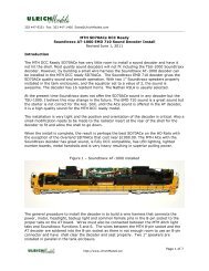
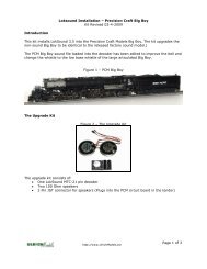
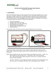
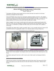
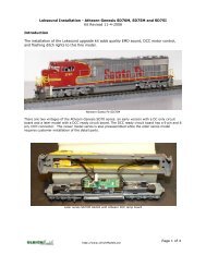
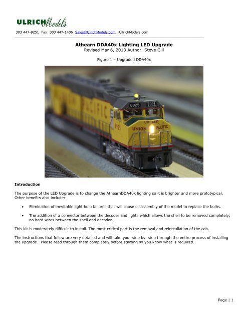
303 447-9251 Fax: 303 447-1406 Sales@<strong>Ulrich</strong><strong>Models</strong>.com Ullrich<strong>Models</strong>.com____________________________________________________________________________________________<strong>Athearn</strong> <strong>DDA40x</strong> <strong>Lighting</strong> <strong>LED</strong> <strong>Upgrade</strong>Revised Mar 6, 2013 Author: Steve GillFigure 1 – <strong>Upgrade</strong>d <strong>DDA40x</strong>IntroductionThe purpose of the <strong>LED</strong> <strong>Upgrade</strong> is to change the <strong>Athearn</strong><strong>DDA40x</strong> lighting so it is brighter and more prototypical.Other benefits also include:Elimination of inevitable light bulb failures that will cause disassembly of the model to replace the bulbs.The addition of a connector between the decoder and lights which allows the shell to be removed completely;no hard wires between the shell and decoder.This kit is moderately difficult to install. The most critical part is the removal and reinstallation of the cab.The instructions that follow are very detailed and will take you step by step through the entire process of installingthe upgrade. Please read through them completely before starting so you know what is required.Page | 1
The Kit ContentsFigure 3 – <strong>DDA40x</strong> <strong>LED</strong> <strong>Upgrade</strong> KitKit contents<strong>LED</strong> Resistor <strong>Lighting</strong> Board with headlight and backup light <strong>LED</strong>s attached (golden white), and 6-pin maleconnector6-Pin female connecter to attach to the sound board1 Strobe <strong>LED</strong>Detail West LN-341 LensesAdhesive mounting tape for attaching the light board to shellFiller material o cover the strobe light openingSmall piece of fiber optic for testing hole sizeSuggested ToolsInstant Glue – I use Hot Stuff, Gap Filling, Instant Glue. It has an orange label. I have tested many CA gluesand I have found this one to be quick setting, great at bonding, and strong. Use a gap filling CA that sets in10-25 seconds. The instant glue is used to reattach the ditch light housings to the platform, install <strong>LED</strong>s intothe ditch light housings, glue <strong>LED</strong>s with attached fiber optics into the lamp holes in the shell and attach theheadlight and backup light lenses.CA gluing tool or micro brushes to help with gluingSmall, high quality needle nose pliersSmall, high quality diagonalsTweezersSmall screwdriversExacto knife or similar type knifeTouchup paint#52 drill and a pin viseFoam pad or model cradlePage | 2
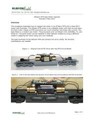
Figure 2 - Completed InstallInstallation procedureFigure 2 shows the completed install. The installation uses our <strong>LED</strong> <strong>Lighting</strong> Resistor Board to save space and makethe wiring easier.Remove the shellRemove the couplers and coupler box from the front and rear. Next remove the two screws that hold the shell to theframe. One is under the rear of the front truck and the other is under the front part of the rear truck. There are alsotwo screws under the fuel tank shell that need to be removed. Once all four screws are removed, slide the shell offcarefully. It is a tight fits so there will be some resistance.Disconnect all lighting wires from the decoder and remove the bulbsThere are 10 lighting wires attached to tabs on the decoder. Four wires for the headlights, four wires for the backuplight and two wires for the strobe. Once the wires are disconnected, the shell can be separated from the frame,motor and decoder.Remove the CabThe first step towards installing the Headlight and strobe light <strong>LED</strong>s is to remove the cab. See Figure 3.Figure 3 – Cab TabsThe cab must be removed carefully to avoid damaging the small metal steps and breaking armrests, sunshades orother small parts.Detach the handrails and the stair guides from the point of attachment to the cab.The cab is removed by releasing the four tabs that hold it to the shell. This is not all that easy. Below is one method:Page | 3
Remove the cab by using a small needle nose plier to release the rear tabs one at a time while pressing down on thetop of the tab enough to make it move down enough to clear the area where it catches; a small distance. Then do theother rear. Take an X-Acto knife and insert it under a rear edge of the cab and lift the rear of the cab up a little a littlefurther. Then work on the front tabs. Once they are released, use the X-Acto knife as a wedge and gently pry the cabup until it can be remove. Make sure the light wires and not holding the cab from coming loose.Install Headlight <strong>LED</strong>s and Strobe /Rotary BeaconRemove the tape over the headlight and strobe bulbs. Take a small pair of pliers and pull the headlight bulbs out. Ifthe bulb breaks off, use a hand drill with #52 drill from the back side to clear the hole. You can also use the drill atthis time to enlarge the holes for the fiber optic and lens. Remove the strobe bulb.Figure 5 – Cab RemovedInstall the Strobe <strong>LED</strong>The Strobe is installed by removing the lens from the strobe housing. To remove the lens grip the lens on top and tiltit slightly. It will come off. There is not much glue holding it. Insert <strong>LED</strong> from the top as shown. No glue required. Putan extremely small amount of CA on the bottom of the strobe lens and reinsert it. The <strong>LED</strong> has to be installed thisway so there is adequate light to have a bright strobe.Figure 6 – Strobe <strong>LED</strong> InstalledPage | 4
Install the Headlight LensesIf you have not drilled out the headlamp holes with the #53 drill, do so now and clear any residue away. Note: It iseasy to lose a Details West lens during the install process so we included a total of ten lenses when only four arerequired.Using a small pair of needle nose pliers, grip one of the lenses on the lens sprue by gripping it front to back betweenthe jaws. Use a good pair of pliers with tread on the inside of the jaws; don’t use smooth jawed needle nose pliers.Rotate the lens back and forth until it comes loose from the sprue. If there is a significant stub attached to the lens,use a fine piece of sandpaper to remove it. Release the lens to a flat surface so that it can be picked up in the properorientation for installation.You may have your own method of installing small lenses but I attach some double sided tape to a screwdriver tip andthen pick the lens up by its curved front.Figure 7 – Lens on tape/screwdriverApply a very small amount of instant glue to the back of the lens then use the screw driver to insert the lens into oneof the lamp holes. To remove the lens from the tape, press down lightly on the lens with the screwdriver blade andslide the taped blade end off the lens. Make sure the lens has been inserted properly. If not align it. In the event thatlens has to be removed it can be pushed out from the inside of the shell using a paper clip or some other smalldiameter tool.Now is a good time to also install the rear backup lenses using the same procedure only use the drill to enlarge andclear the backup light holes from the outside of the shell due to restrictions.Page | 5
Carefully slip the back edge of the cab into the slots in the body making sure the metal steps clear. Slide the cabslowly down until it is ready to push the tabs back into place. As you slide the cab down, pull the strobe wirethrough and make sure it ends up in the slot in the body for wires. Also, if the steps catch on the shell (almostcertain to happen) you can use a small tool like an Exacto knife to put a little pressure to on the cab panel thatholds the steps to flex the steps away from the body. Push the cab down and make sure the clips set. Tape theheadlight wires to the bottom of the cab.Figure 9 - Cab ReinstallationInstall Resistor BoardPrior to installing the Resistor board, the strobe <strong>LED</strong> must be soldered to output 5 on the Resistor board. Supportthe Resistor board and position the resistor board near the ends of the wires for the strobe. Solder the wire with thelonger stripped lead to the common (anode) pad for output 5. The Common pad has a white box around it. Solderthe short lead to the negative or function side (Cathode).Apply the double sided mounting tape to the back of the resistor board and attach it to the top of the shell as shownin the figure 10. Route the <strong>LED</strong> leads through the two guides and arrange excess lead wire to be out of the waythen secure with tape.Figure 10 – Resistor Board and Headlight <strong>LED</strong>s InstalledPage | 7
Route the Rear <strong>LED</strong> LeadFeed the rear <strong>LED</strong>s through the slot in the shell one at a time. Keep the <strong>LED</strong>s to the inside for easier passage. Thesplice covered by heat shrink tubing also needs to pass through.Install Rear <strong>LED</strong>sRemove the two wire guides the extend form the top of the shell right behind the backup light holes. You can removethem by grabbing both of them in the jaws of some small pliers and squeezing them together. One will break off. Oneit is removed, take the pliers and flex the other guide to the side. It will break off.It’s a good idea to make sure the fiber optics fit into the hole prior to applying glue. Once you have verified the fiberoptic tubes fit into the holes, put a touch of CA on the end of one rear fiber optic and using tweezers or small needlenose pliers, grab the <strong>LED</strong> tube by the end of the heat shrink where it is flattened or on the tube and insert the front ofthe light tube into one of the holes. Do not grip where the <strong>LED</strong> and tube are attached. Each tube must be held in placefor 20-60 seconds depending on CA set time. Once you release the tube, give it a few minutes to set before installingthe second one.Figure 11 – Rear <strong>LED</strong> InstallationSecure the <strong>LED</strong> wires to the shell top using tape.Optional lighting testIf you have an <strong>LED</strong> Tester, you can test the lighting prior to attaching the harness to the decoder. Test using 12-20mA. The lights will not be as bright as when operating the locomotive but they will light.If you do not have an <strong>LED</strong> Tester, skip this section of the document. The lighting will be tested prior to full assemblyon the track.Plug the female end of the harness into the connector for the shell.Connect the + (positive) lead from the tester to the blue (common) wire.Connect the – (negative) to the wires listed below to test the lightingWhiteGrayRedHeadlightBackupStrobePage | 8
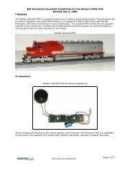
Solder the wire harness to the decoderFigure 12– Harness Soldered to DecoderIt is possible to use the <strong>Athearn</strong> plastic caps when installing the harness, however, soldering is recommended forbetter contact. In fact, we recommend soldering all wires to the decoder tabs for trouble free electrical contact.Note: The picture above shows a male connector. In the kit supplied the connector will be female.Figure 13 – Soundtraxx Decoder board Harness wiringSolder the wires as follows:Gray Wire – Backup Light TabWhite wire - Headlight TabBlue Wire - +14 Volt CommonRed Wire - F6 – StrobeOrange Wire – F5 (Not used)Prior to full reassembly, it is best to test the locomotive. Connect the connector between the lighting board and thedecoder. Be sure to align the connector so that the color of the wires matches on both halves. Set the shell on theframe but do not push it down all the way.Place the locomotive on the track and test using the correct locomotive address. Turn on the headlight and makesure all the lights work. Reverse the locomotive and make sure both backup <strong>LED</strong>s light. Press F6 and insure thestrobe lightsIf all works well, the shell can be but back on the frame properly. Watch that wires do not get caught while slidingthe shell down. Install the two screws that hold the shell on before doing the couplers.Figure 14 - Completed InstallPage | 9
CV ProgrammingTo improve the F7 dimming of the <strong>LED</strong> headlights and ditch lights, reprogram the ditch lights and headlightsas specified below. The <strong>LED</strong> bit must be added to the lighting feature. However, the dim level is still higherthan optimum. The Soundtraxx decoder has only one fixed dim level.Function MappingCV 40 = 4 FX6 = output FX 6 (Default)FX6 Hyperlight EffectsCV 52 = 135 <strong>LED</strong> + Rotary BeaconCV 52 = 133 <strong>LED</strong> + Single Strobe (Alternate programming)Headlight ChoicesCV49 = 129 (Dimmable Headlight +<strong>LED</strong>) Dims with F7CV49 = 143 (Dynolight + <strong>LED</strong>)Headlight Backup LightBackup CV50 =143 (Dynolight + <strong>LED</strong>)Sounds starts with Throttle stepCV 116 = 71 (Sound starts with throttle packet + Notch rate =7)Add 64 to the desired notch increment (0-15) to obtain value.Do add 64 if you want the sound to start as soon as power is appliedPage | 10
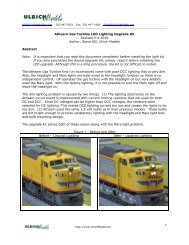
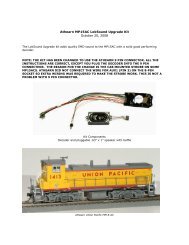
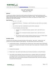
____________________________________________________________________________________________Abstract<strong>Ulrich</strong> <strong>Lighting</strong> Resistor BoardCopyright - <strong>Ulrich</strong> <strong>Models</strong> 2010December 23 , 2010The goal was to design a board that made installing <strong>LED</strong> lighting into HO scale locomotives much easier especiallywhen using miniature surface mount <strong>LED</strong>S on 6” leads. The <strong>Lighting</strong> Resistor board makes converting <strong>Athearn</strong> Dieselsto <strong>LED</strong> lighting much easier and reduces the number of wires between the shell and the decoder.Specificationso Size 1.5 “ x .5” x .06”ooo6 Supported Functions - 6 functions in and 6 functions out each with its own resistor pad.One common input that is distributed to each function output pairFor dual headlights and backup lights• Function #1 is connected to function outputs 1 and 2, each with its own resistor.• Function #3 is connected to function outputs 3 and 4, each with its own resistor.• The connection path to jumper the above outputs can be cut to isolate output 1 and 2, and 3and 4 for a total of 8 functions with resistors.Problems solvedThe past issue with lighting conversion has been all the splicing, heat shrink, resistor bulk, and common wirejunctions needed to install lighting. This board solves these issues as follows:Common Wire Junctions – The board has one common input. That common input is distributed to every pair ofoutput function pads. The common pad of each output pair is marked by a white outline.No heat shrink requiredResistor bulk – Uses small ¼ watt surface mount resistors mounted on a narrow thin boardThe number of wires between the shell and the drive in a <strong>Athearn</strong> diesel can be reduced by mounting theboard in the shell and only running the function outputs and common to the board. With use of a smallconnector between the board and the shell, the shell can easily be removed from the locomotive.Figure 1 - Unpopulated <strong>Ulrich</strong> <strong>Lighting</strong> Resistor BoardPage | 11
Figure 2 – Populated Board with 1K ResistorsPage | 12
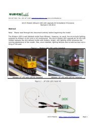
Figure 3 -Board SchematicF303 447-9251 Fax: 303 447-1406 Sales@<strong>Ulrich</strong><strong>Models</strong>.comGeneral<strong>LED</strong> <strong>Lighting</strong> Basics (Revised 29-Nov-2010)<strong>LED</strong>s are actually diodes that emit light. They are semi-conductor devices and are not related to incandescent bulbs atall. Since they are diodes, for all practical purposes, they only conduct current in one direction. To conduct current,the <strong>LED</strong> anode must be connected to a positive voltage source and the cathode to a negative voltage source. Whenthe applied voltage reaches the voltage threshold for the <strong>LED</strong>, current will flow and the <strong>LED</strong> will light. The voltagerequired for the <strong>LED</strong>s used in model railroading varies between 1.2 and about 1.5 volts.Since decoders do not have voltage adjustable outputs, it is best to think of <strong>LED</strong>s as current devices. Decoder voltageoutput is usually 12-14 volts or 5 volts depending on the decoder. 12-14 volts is the most common.Identifying <strong>LED</strong> polarityFor surface mount <strong>LED</strong>s with 6” leads, the long stripped lead is the anode. If you cut the leads, the only way todetermine polarity is by testing the <strong>LED</strong> to see which polarity lights it. We sell an <strong>LED</strong> tester that is quite handy forthat purpose.Figure 2 – Surface Mount <strong>LED</strong>Page | 13
For 3 mm and 5 mm <strong>LED</strong>s you can visually identify the Anode and Cathode. Also, until the leads are cut, the Anode isthe longer lead.Figure 1 – 3 mm and 5 mm <strong>LED</strong>sResistor Values for <strong>LED</strong>sWire all <strong>LED</strong> anodes to the +12-14 common (blue wire). Connect each <strong>LED</strong> cathode to a negative function outputthrough a resistor.The current value for <strong>LED</strong>s is calculated using Ohms Law. I = V/R where I is current, V is voltage and R is resistance.The target current value for 3 and 5 mm <strong>LED</strong>s is 20 mA. For miniature surface mount <strong>LED</strong>s, the target current is 12-14 mA3 mm and 5 mm <strong>LED</strong>sPage | 14
For 3 mm <strong>LED</strong>s the normal resistor is a 560 Ohm ½ watt resistor. This runs the <strong>LED</strong> at 20-25 mA (milliamps)which gives normal brightness. Use a higher value resistor for less light output. 20 mA is a good target value for3 and 5 mm <strong>LED</strong>sSurface Mount <strong>LED</strong>sFor the miniature surface mount <strong>LED</strong>s, use a 1K resistor or 1.2K Ohm ¼ or ½ watt resistor. Use one resistor foreach negative function output. A 1K resistor runs the <strong>LED</strong> at 12-14 mA which is quite bright. We use 1K ¼ wattresistors in our models. For less brightness, use a larger value resistor. 20 mA is the absolute maximum currentfor the surface mount <strong>LED</strong>s. It is a good idea to stay below the maximum current.Testing <strong>LED</strong>sThe polarity of a surface mount <strong>LED</strong> with 6” leads can be determined using an <strong>LED</strong> tester (shown in Figure 3). Inserta 3 mm <strong>LED</strong> into the desired current position in the <strong>LED</strong> tester. Using a 3 mm <strong>LED</strong> to plug into the current contacts onthe tester, gives you a visual indication when current is flowing.Connect one end of the test lead clip to the 3 mm <strong>LED</strong> anode (+) and one end of the other test lead clip to thecathode (-).Clip the other end of the leads to the two stripped portions of the miniature <strong>LED</strong> leads. If the <strong>LED</strong> leads are stillfactory stripped, connect the positive clip lead to the anode (long stripped wire) and the negative end to the cathode.If you cannot determine which lead is the longer stripped lead, then you will have to discover the polarity byprocesses of elimination. Try one polarity and then reverse the polarity if the <strong>LED</strong> does not light.By using different current settings you can also determine the desired current value for the <strong>LED</strong>..Figure 3 – <strong>LED</strong> Test SetupWhen installing Miniature <strong>LED</strong>s into a locomotive, it is sometimes difficult to trace the wires to the <strong>LED</strong>. As a result,you do not know which <strong>LED</strong> leads are for a particular <strong>LED</strong>. Using the <strong>LED</strong> tester on a set of <strong>LED</strong> leads will illuminatethe <strong>LED</strong> so you can determine which <strong>LED</strong> lights for the particular lead pair you are checking. The tester will light the<strong>LED</strong> even if a 1K resistor is in the circuit. It will not be as bright but it will light.Page | 15