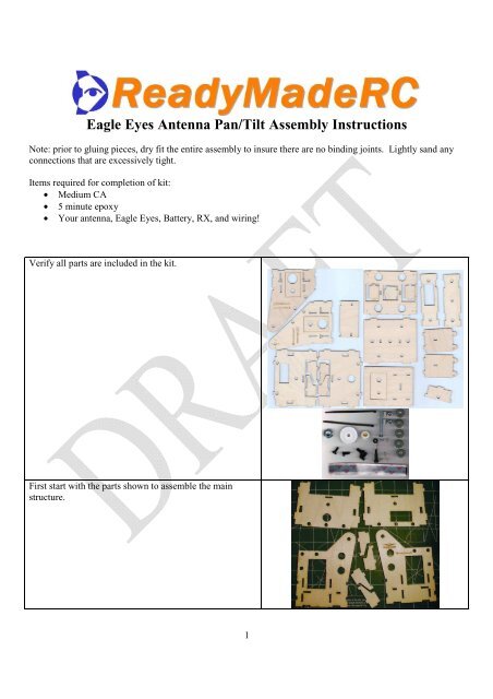
Eagle Eyes Antenna Pan/Tilt Assembly Instructions - Allendale Stores
Eagle Eyes Antenna Pan/Tilt Assembly Instructions - Allendale Stores
Eagle Eyes Antenna Pan/Tilt Assembly Instructions - Allendale Stores
- No tags were found...

Create successful ePaper yourself
Turn your PDF publications into a flip-book with our unique Google optimized e-Paper software.
<strong>Eagle</strong> <strong>Eyes</strong> <strong>Antenna</strong> <strong>Pan</strong>/<strong>Tilt</strong> <strong>Assembly</strong> <strong>Instructions</strong><br />
Note: prior to gluing pieces, dry fit the entire assembly to insure there are no binding joints. Lightly sand any<br />
connections that are excessively tight.<br />
Items required for completion of kit:<br />
• Medium CA<br />
• 5 minute epoxy<br />
• Your antenna, <strong>Eagle</strong> <strong>Eyes</strong>, Battery, RX, and wiring!<br />
Verify all parts are included in the kit.<br />
First start with the parts shown to assemble the main<br />
structure.<br />
1
Lay the side supports as shown, and install the small<br />
reinforcement pieces.<br />
Install the servo horn using the four included small<br />
screws. Install it on the left support pictured in the<br />
previous step.<br />
Install bottom platform to side support as shown.<br />
Install spacer as shown.<br />
Install top platform as shown.<br />
2
Combine with second side support.<br />
Obtain the three pieces for the tripod mount shown. The<br />
medium sized holes in the bottom of each part will all be<br />
aligned during the assembly in the next step.<br />
Apply glue to the first piece as shown. Add the second<br />
identical piece next, and add glue to the top of that piece.<br />
Add the third piece, making sure the medium holes are<br />
aligned.<br />
Using a hammer, insert the tee-nut on the side of the<br />
support shown.<br />
Insert the bolt with one washer as shown.<br />
3
On the opposite side, add a washer and a nut. Tighten<br />
securely.<br />
Add another washer and one of the threaded spacers.<br />
With a hobby knife, scrape a small amount of material<br />
from the holes on the top and bottom plates until the<br />
threaded spacer slides through without binding. Do not<br />
remove too much material or there will be excess slop in<br />
the pan assembly.<br />
Insert the bolt into the hole on the bottom plate.<br />
With the bolt partially inserted through the bottom hole,<br />
slide in the small gear and slide the bolt through the gear.<br />
A set of needle nose pliers may be helpful in this step for<br />
holding the gear.<br />
Using needle-nosed pliers, add a washer above the gear.<br />
4
Insert the bolt through the hole on the top plate, and add<br />
the second threaded spacer.<br />
Add the last washer and the nut to the bolt and tighten<br />
securely. A good amount of force is helpful to prevent<br />
any slippage of the assembly during use. At this time you<br />
should also tighten the set screw on the gear.<br />
Sand the face of the servo arm so it is smooth.<br />
Making sure the servo arm is centered, use 5 minute epoxy<br />
to secure the servo to the gear. Be careful and make sure<br />
no epoxy gets into the gears.<br />
Alternatively, you may use the four screws as shown.<br />
Slide the gear into the bottom plate as shown.<br />
5
After adding the spacers included with the servos, place<br />
the servo in the hole as shown and push the gear assembly<br />
onto the servo shaft. Making sure the servo gear is<br />
engaging the smaller gear snugly, screw the servo into<br />
place using the included screws.<br />
Screw gear assembly to servo.<br />
Obtain the parts shown for the antenna mounting bracket.<br />
Add the two spacers to the front plate as shown.<br />
Add the back plate as shown.<br />
6
Add the side supports as shown.<br />
Mount the servo as shown.<br />
Insert the screw through the hole on the side plat and into<br />
the hole on the side of the antenna support.<br />
Add the nut to the inside and tighten securely.<br />
With the servo centered, align the antenna support to the<br />
line shown (no line on beta models, align at a 45 degree<br />
angle from vertical). Attach servo to servo horn on the<br />
side support.<br />
NEED PICTURE<br />
7
The antenna should be installed with the cable coming out<br />
of the top or bottom and should be centered as much as<br />
possible on the mount. For the standard L-Com large<br />
antennas typically one large and two small bolt holes will<br />
line up. For the smaller 8dBi 2.4GHz antennas, the<br />
mounting hole on the antenna will line up with the center<br />
hole on the mount. The recommended antenna for<br />
2.4GHz systems using the Duo2400 is the 11dBi diversity<br />
antenna available here.<br />
Depending on the receiver type, the receiver can be<br />
mounted either with hook-and-loop or with screws. Make<br />
sure there is clearance for the tilt assembly to move to the<br />
vertical position.<br />
The <strong>Eagle</strong> <strong>Eyes</strong> unit is mounted to the side plate (BETA<br />
VERSION SHOWN).<br />
NEED PICTURE<br />
Make sure wiring is free from binding. Sample<br />
Pictures will be added once final <strong>Eagle</strong> <strong>Eyes</strong> units<br />
installation is shown.<br />
are delivered.<br />
OPTIONAL “SIDE CAR” Installation <strong>Instructions</strong><br />
The “side car” can be used to mount a second receiver with a vertical whip antenna or as a spot to mount<br />
additional equipment.<br />
Pieces Used<br />
8
Assemble as shown<br />
Hangs on either side of pan/tilt unit<br />
9