Luno Model 8160 Manual - Hearthstone Stoves
Luno Model 8160 Manual - Hearthstone Stoves
Luno Model 8160 Manual - Hearthstone Stoves
- No tags were found...

You also want an ePaper? Increase the reach of your titles
YUMPU automatically turns print PDFs into web optimized ePapers that Google loves.
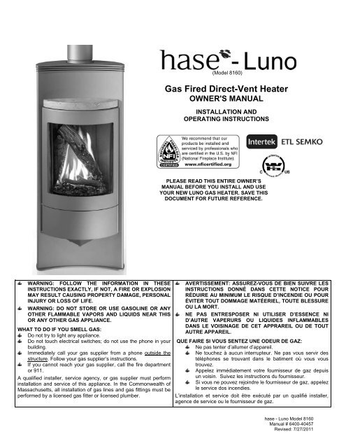
(<strong>Model</strong> <strong>8160</strong>)<br />
Gas Fired Direct-Vent Heater<br />
OWNER'S MANUAL<br />
INSTALLATION AND<br />
OPERATING INSTRUCTIONS<br />
PLEASE READ THIS ENTIRE OWNER’S<br />
MANUAL BEFORE YOU INSTALL AND USE<br />
YOUR NEW LUNO GAS HEATER. SAVE THIS<br />
DOCUMENT FOR FUTURE REFERENCE.<br />
WARNING: FOLLOW THE INFORMATION IN THESE<br />
INSTRUCTIONS EXACTLY, IF NOT, A FIRE OR EXPLOSION<br />
MAY RESULT CAUSING PROPERTY DAMAGE, PERSONAL<br />
INJURY OR LOSS OF LIFE.<br />
WARNING: DO NOT STORE OR USE GASOLINE OR ANY<br />
OTHER FLAMMABLE VAPORS AND LIQUIDS NEAR THIS<br />
OR ANY OTHER GAS APPLIANCE.<br />
WHAT TO DO IF YOU SMELL GAS:<br />
Do not try to light any appliance.<br />
Do not touch electrical switches; do not use the phone in your<br />
building.<br />
Immediately call your gas supplier from a phone outside the<br />
structure. Follow your gas supplier’s instructions.<br />
If you cannot reach your gas supplier, call the fire department<br />
or 911.<br />
A qualified installer, service agency, or gas supplier must perform<br />
installation and service of this appliance. In the Commonwealth of<br />
Massachusetts, all installation of gas lines and gas fittings must be<br />
performed by a licensed gas fitter or licensed plumber.<br />
AVERTISSEMENT: ASSUREZ-VOUS DE BIEN SUIVRE LES<br />
INSTRUCTIONS DONNÉ DANS CETTE NOTICE POUR<br />
RÉDUIRE AU MINIMUM LE RISQUE D’INCENDIE OU POUR<br />
ÉVITER TOUT DOMMAGE MATÉERIEL, TOUTE BLESSURE<br />
OU LA MORT.<br />
NE PAS ENTRESPOSER NI UTILISER D’ESSENCE NI<br />
D’AUTRE VAPERURS OU LIQUIDES INFLAMMABLES<br />
DANS LE VOISINAGE DE CET APPRAREIL OU DE TOUT<br />
AUTRE APPAREIL.<br />
QUE FAIRE SI VOUS SENTEZ UNE ODEUR DE GAZ:<br />
Ne pas tenter d’allumer d’appareil.<br />
Ne touchez à aucun interrupteur. Ne pas vous servir des<br />
téléphones se trouvant dans le batiment où vous vous<br />
trouvez.<br />
Appelez immédiatement votre fournisseur de gaz depuis<br />
un voisin. Suivez les instructions du fournisseur.<br />
Si vous ne pouvez rejoindre le fournisseur de gaz, appelez<br />
le service dos incendies.<br />
L’installation et service doit être exécuté par un qualifié installer,<br />
agence de service ou le fournisseur de gaz.<br />
hase - <strong>Luno</strong> <strong>Model</strong> <strong>8160</strong><br />
<strong>Manual</strong> # 6400-40457<br />
Revised: 7/27/2011
HearthStone Quality Home Heating Products, Inc. <strong>Luno</strong> <strong>Model</strong> #<strong>8160</strong><br />
Intentionally Blank<br />
1
HearthStone Quality Home Heating Products, Inc. <strong>Luno</strong> <strong>Model</strong> #<strong>8160</strong><br />
Information Sheet<br />
Use this page to record all relevant information concerning the purchase, installation, and maintenance of your<br />
<strong>Luno</strong> <strong>Model</strong> <strong>8160</strong> Direct -Vent heater. This information will facilitate servicing, purchase of replacement parts,<br />
and warranty claims (if necessary). Keep your original receipt in a safe place as proof of purchase.<br />
Serial Number:<br />
Fuel type: Natural Gas Liquid Propane<br />
Sold by:<br />
Address:<br />
Phone:<br />
E-mail<br />
Installed by:<br />
Address:<br />
Phone:<br />
E-mail<br />
Gas Supplier:<br />
Address:<br />
Phone:<br />
E-mail<br />
Date of Purchase:<br />
Website:<br />
Date of Installation:<br />
Website:<br />
Website:<br />
Read this Owner’s <strong>Manual</strong> before installing, or operating your <strong>Luno</strong>. Retain this manual for future reference.<br />
SERVICE RECORD<br />
Date Who Performed Work Work Performed Notes:<br />
WHAT<br />
Firebox Cleaning.............<br />
Glass Cleaning................<br />
Door Gasket....................<br />
WHEN<br />
annually<br />
as needed<br />
Replacement as needed<br />
1
HearthStone Quality Home Heating Products, Inc. <strong>Luno</strong> <strong>Model</strong> #<strong>8160</strong><br />
TABLE OF CONTENTS<br />
INTRODUCTION ....................................................................................................................................2<br />
SPECIFICATIONS..................................................................................................................................3<br />
OWNER’S INFORMATION ....................................................................................................................4<br />
Daily Operation........................................................................................................................................................ 4<br />
Service Caution ....................................................................................................................................................... 4<br />
INSTALLER’S INFORMATION..............................................................................................................5<br />
ITEMS REQUIRED FOR INSTALLATION.............................................................................................5<br />
SPECIFIED VENTING MANUFACTURER CONTACT INFORMATION ...............................................5<br />
UNPACKING AND INSPECTION ..........................................................................................................5<br />
INSTALLATION .....................................................................................................................................6<br />
Hearth & Floor Protection Requirement .................................................................................................................. 6<br />
Clearance To Combustibles.................................................................................................................................... 6<br />
Opening the front door ............................................................................................................................................ 6<br />
Installing the Decorative Top Stone ........................................................................................................................ 6<br />
VENTING INFORMATION .....................................................................................................................9<br />
ELECTRICAL CONNECTIONS ...........................................................................................................12<br />
GAS SUPPLY & CONNECTIONS .......................................................................................................13<br />
FIRE LOG PLACEMENT .....................................................................................................................14<br />
LIGHTING THE UNIT FOR THE FIRST TIME .....................................................................................15<br />
INITIAL ADJUSTMENTS .....................................................................................................................16<br />
ROUTINE MAINTENANCE AND CARE ..............................................................................................18<br />
PARTS LIST:........................................................................................................................................21<br />
BOLTING YOUR LUNO GAS STOVE TO A PERMANENT STRUCTURE ........................................21<br />
HIGH ALTITUDE INSTALLATIONS ....................................................................................................22<br />
TROUBLESHOOTING .........................................................................................................................23<br />
RATING LABEL...................................................................................................................................26<br />
1
HearthStone Quality Home Heating Products, Inc. <strong>Luno</strong> <strong>Model</strong> #<strong>8160</strong><br />
Congratulations on your purchase of <strong>Hearthstone</strong>’s<br />
<strong>Luno</strong> <strong>Model</strong> <strong>8160</strong> Gas-Fired Direct Vent heater. The<br />
<strong>Luno</strong> incorporates the latest in balanced vent gas<br />
technology, which will provide you with clean,<br />
efficient heat for years to come. Combustion air<br />
comes directly from the outside of your home to the<br />
sealed firebox system, eliminating the potential for<br />
annoying back drafts or other problems associated<br />
with home depressurization.<br />
The <strong>Luno</strong> will provide you with years of practical and<br />
convenient service. However, as with any gas<br />
appliance, the unit must be properly and safely<br />
installed and maintained by qualified service<br />
personnel to ensure safe and trouble-free operation.<br />
READ THIS OWNER’S MANUAL<br />
Operate and maintain this gas heater according to<br />
the instructions in this manual. For your safety, and<br />
years of trouble free operation, read this manual in its<br />
entirety. By following a few simple safety precautions<br />
and by performing minimal maintenance, the unit will<br />
remain appealing while providing years of quality<br />
performance.<br />
WARNING: ENSURE ONLY AN NFI CERTIFIED<br />
SERVICE TECHNICIAN INSTALLS, AND REPAIRS<br />
THIS APPLIANCE. A QUALIFIED SERVICE<br />
TECHNICIAN MUST INSPECT THE APPLIANCE<br />
BEFORE USE, AND AT LEAST ANNUALLY. MORE<br />
FREQUENT CLEANING MAY BE REQUIRED DUE<br />
TO EXCESSIVE LINT FROM CARPETING, BEDDING<br />
MATERIAL, PETS, ETC. IT IS IMPERATIVE THAT<br />
THE CONTROL COMPARTMENTS, BURNERS, AND<br />
CIRCULATING AIR PASSAGES OF THE<br />
APPLIANCE ARE KEPT CLEAN AND FREE OF<br />
OBSTRUCTIONS. (S’ASSURER QUE LE BRÛLEUR<br />
ET LE COMPARTIMENT DES COMMANDES SONT<br />
PROPRES. VOIR LES INSTRUCTIONS<br />
D’INSTALLATION ET D’UTILISATION QUI<br />
ACCOMPAGNENT L’APPAREIL.)<br />
WARNING: DO NOT OPERATE THIS APPLIANCE<br />
WITH THE GLASS, OR ANY PANEL REMOVED,<br />
CRACKED, OR BROKEN. DO NOT SUBJECT THE<br />
DOOR TO ABUSE, SUCH AS STRIKING OR<br />
SLAMMING SHUT. REPLACEMENT OF THE GLASS<br />
PANEL SHOULD BE DONE BY A LICENSED OR<br />
QUALIFIED SERVICE PERSON.<br />
INTRODUCTION<br />
REQUIRED FUELS<br />
This gas heater is designed to burn natural gas, or<br />
when converted, liquid propane (LP). Never burn any<br />
fuel not intended for use with this unit.<br />
HOT SURFACES<br />
Certain exposed surfaces of the <strong>Luno</strong> will reach high<br />
temperatures during normal operation. Clearances to<br />
combustibles must be maintained, as specified in the<br />
“Clearances to Combustibles” section of this manual.<br />
Do not use this appliance if any part has been under<br />
water. Immediately call a qualified service technician to<br />
inspect the heater and to replace any part of the control<br />
system and gas control that has been under water. (Ne<br />
pas se servir de cet appareil s’il a été plongé dans l’eau,<br />
complétement ou en partie. Appeler un technicien qualifié<br />
pour inspector l’appareil et remplacer toute partie du<br />
systéme de contrôle et toute commande qui ont été<br />
plunges dans l’lau.)<br />
WARNING: THIS GAS APPLIANCE MUST NOT BE<br />
CONNECTED TO A CHIMNEY FLUE SERVING A<br />
SEPARATE VENTED APPLIANCE. NEVER VENT<br />
THE GAS HEATER TO OTHER ROOMS OR<br />
BUILDINGS. MASONRY CONVERSIONS KITS ARE<br />
AN ACCEPTABLE VENTING OPTION.<br />
Due to high temperatures locate the appliance<br />
out of traffic and away from furniture, draperies,<br />
clothing and flammable materials. Alert children<br />
and adults to the hazards of high surface<br />
temperatures and to stay away to avoid burns to<br />
skin or clothing ignition. Ensure young children<br />
are carefully supervised when in the same room<br />
as the appliance. Do not place clothing or other<br />
flammable material on or near the appliance.<br />
(Surveille les enfants. Garder les vêtements, les<br />
meubles, l’essence ou autres liquides à vapeur<br />
inflammables lin de l’appareil.)<br />
FIRE HAZARD<br />
Do not store or use gasoline or other flammable<br />
vapors or liquids in the vicinity of this appliance.<br />
Locate the <strong>Luno</strong> out of traffic and away from furniture,<br />
draperies, clothing, and flammable material.<br />
2
HearthStone Quality Home Heating Products, Inc. <strong>Luno</strong> <strong>Model</strong> #<strong>8160</strong><br />
Listed as: Gas-Fired Direct-Vent Fireplace Heater<br />
<strong>Model</strong>: <strong>Luno</strong> Direct-Vent Gas Fireplace Heater<br />
(<strong>Model</strong> #<strong>8160</strong>)<br />
Testing Agency: Intertek Testing Services<br />
Tested to: ANSI Z21.88b-2005/CSA 2.33b-2005,<br />
CGA 2.17-M91<br />
Report No. 3092115-T4<br />
SPECIFICATIONS<br />
Certified for US and Canada<br />
Approved for Mobile Home Installation.<br />
Certified for use by:<br />
Board of State Examiners of Plumbers and Gasfitters<br />
100 Cambridge Street, Room 1511<br />
Boston, Massachusetts 02202<br />
FUEL TYPE: NG LP<br />
INPUT RATING (Btu/hr) 0-2000 ft 26,500 26,500<br />
INPUT RATING (Btu/hr) 2000-4000 ft 26,500 26,000<br />
ORIFICE SIZE (DMS) 0-2000 ft 38 52<br />
ORIFICE SIZE (DMS) 2000-4500ft) 38 53<br />
MANIFOLD PRESSURE - LO SETTING (in. W.c./kpa) 1.2/0.3 3.3/0.8<br />
MANIFOLD PRESSURE - HI SETTING (in. W.c./kpa) 3.5/0.87 10.0/2.48<br />
MINIMUM INLET PRESSURE - (in.w.c./kpa) 5.0/1.24 11.0/2.88<br />
MAXIMUM INLET PRESSURE- (in.w.c./kpa) 7.0/1.74 13.0/3.22<br />
MINIMUM INPUT RATING (btu/hr) 16,000 15,000<br />
MAXIMUM OUTPUT (btu/hr) 0-2000 ft 20,400 20,200<br />
Table 1 - <strong>Luno</strong> Fuel and Output Specifications<br />
Figure 1 – <strong>Luno</strong> <strong>8160</strong> Dimensions<br />
3
HearthStone Quality Home Heating Products, Inc. <strong>Luno</strong> <strong>Model</strong> #<strong>8160</strong><br />
The installation must conform with local codes or, in<br />
the absences of local codes, the current National Fuel<br />
Gas Code, ANSI Z223.1 (NFPA 54) or CAN/CGA<br />
B149 Installation Code. (Installer l’appareil selon les<br />
codes ou règlements locaux, ou, en l’absence de tels<br />
règlements, selon les Codes d’installation CAN/CGA-<br />
B149.)<br />
Contact your dealer for any necessary warranty<br />
service.<br />
This stove is warranted by:<br />
<strong>Hearthstone</strong> Quality Home Heating Products,<br />
Inc®<br />
317 Stafford Ave.<br />
Morrisville, Vermont 05661<br />
DAILY OPERATION<br />
The <strong>Luno</strong> is easily operated by the homeowner once<br />
it is installed and adjusted by qualified service<br />
personnel. The unit can be controlled automatically<br />
via the programmable remote control, or manually by<br />
placing the Remote Control Receiver switch in the<br />
‘ON’ position during the heating season. When using<br />
the remote T-stat transmitter (switch in the ‘REMOTE’<br />
position), set it to the desired room temperature and<br />
the unit will cycle on and off as required. If you select<br />
the ‘ON’ position the unit will run (burn) regardless of<br />
room temperature. You can vary the rate of heat<br />
output by adjusting the variable output control located<br />
on the gas control valve to meet the heating<br />
requirements of the season. Choosing a low flame<br />
setting will result in longer burn cycles at a reduced<br />
output, while choosing a high flame setting will result<br />
in a shorter, hotter burn cycle. Through trial and error,<br />
the homeowner can select the optimum flame size for<br />
their setting and application.<br />
During the summer non-heating season, switch the<br />
remote receiver to “OFF”, and turn off the pilot. This<br />
will improve the overall efficiency of the unit as the<br />
fuel used by the pilot is wasted. When putting the unit<br />
back into service, follow the lighting instructions<br />
described on page 16.<br />
When the unit is first lit, especially when cool, it is<br />
normal to experience some condensation on the<br />
inside of the window glass. This condensation will<br />
evaporate within the first few minutes of operation. If<br />
you note continuous condensation on the window<br />
glass or dripping water from any part of the unit or<br />
venting system (chimney), immediately discontinue<br />
OWNER’S INFORMATION<br />
operation of the unit and contact qualified service<br />
personnel.<br />
Clean the area around, under, and behind the unit on<br />
a regular basis to prevent the accumulation of dust<br />
and lint.<br />
The <strong>Luno</strong> requires minimal routine maintenance and<br />
care. Ensure the <strong>Luno</strong> is cool and off while cleaning,<br />
or servicing. Have qualified service personnel<br />
inspect the unit, and venting system once a year to<br />
insure that they are clean, free of obstructions, safe,<br />
and in good working order. If service or maintenance<br />
is required, ensure qualified service personnel<br />
perform it.<br />
SERVICE CAUTION<br />
If you believe your <strong>Luno</strong> is in any way, not performing<br />
properly, immediately discontinue operation until the<br />
unit is inspected and approved by qualified service<br />
personnel. Prior to servicing the unit, turn the valve<br />
control knob clockwise to “OFF”. The unit should be<br />
cool prior to servicing and cleaning. Use of any<br />
components not supplied by <strong>Hearthstone</strong> on the<br />
stove voids all warranties. Do not substitute<br />
components.<br />
CAUTION: REPLACE ANY SHIELD, DOOR, OR<br />
SAFETY SCREEN COMPONENT REMOVED FOR<br />
SERVICING, PRIOR TO OPERATING THE UNIT.<br />
WARNING: FAILURE TO POSITION THE PARTS IN<br />
ACCORDANCE WITH THESE DIAGRAMS OR<br />
FAILURE TO USE ONLY THE PARTS<br />
SPECIFICALLY APPROVED WITH THIS<br />
APPLIANCE MAY RESULT IN PROPERTY DAMAGE<br />
OR PERSONAL INJURY.<br />
Conditionally approved for purchased mobile home<br />
installation. This appliance may be installed in an<br />
aftermarket permanently located, manufactured (mobile)<br />
home, where permitted by local codes.<br />
This appliance is only for use with the types of gas<br />
indicated on the rating plate (NG and LP). This appliance is<br />
factory set to burn Natural Gas (NG), but is easily<br />
converted for use with Liquid Propane (LP) with the<br />
included conversion kit. Only a qualified service technician<br />
should convert this stove.<br />
Cet appareil peut être installé dans un maison préfabriquée<br />
(mobile) déjà installée à demeure si les règlements locaux<br />
le permettent.<br />
Cet appareil doit être utilisé uniquement avec les types de<br />
gas indiqués sur la plaque signalétique. Ne pas l’utiliser<br />
avec d’autres gas sauf si un kitde conversion certifié est<br />
installé<br />
4
HearthStone Quality Home Heating Products, Inc. <strong>Luno</strong> <strong>Model</strong> #<strong>8160</strong><br />
CODES<br />
Adhere to all local codes or, in their absence, the<br />
latest edition of THE NATIONAL FUEL GAS CODE<br />
ANSI Z223.1 (NFPA 54) or CAN/CGA B149.<br />
Installation Code that can be obtained from:<br />
AMERICAN NATIONAL STANDARDS INSTITUTE, INC.<br />
1430 BROADWAY<br />
NEW YORK, NY 10018<br />
OR<br />
NATIONAL FIRE PROTECTION ASSOCIATION, INC.<br />
BATTERY MARCH PARK<br />
QUINCY, MA 02269<br />
A manufactured home (mobile) OEM installation must<br />
conform to the Manufactured Home Construction and<br />
Safety Standard, Title 24 CFR, Part 3280 (U.S.) or<br />
Standard for Manufactured Home Installation,<br />
ANSI/NCBCS A225.1 or Standard for Gas Equipped<br />
Recreational Vehicles and mobile Housing, CSA<br />
Z240.4.CAN/SCA Z240 MH (Canada). (Installer<br />
l’appareil selon les codes ou règlements locaux, ou,<br />
en l’absence de tels règlements, selon les Codes<br />
d’installation CAN/CGA-B149.)<br />
ITEMS REQUIRED FOR INSTALLATION<br />
* External regulator<br />
* Piping which complies with state and local codes<br />
* Pipe sealant approved for use with fuel gas (resistant to<br />
sulfur compounds)<br />
* <strong>Manual</strong> shutoff valve<br />
* Sediment trap (see page 14)<br />
* Tee joint<br />
* Pipe wrench<br />
* Phillips head screwdriver<br />
* 7/16-inch wrench<br />
* Other parts as required by state or local code<br />
*Safety Glasses<br />
*Gloves<br />
PACKING LIST<br />
1-<strong>Luno</strong> Gas-Fired Heater<br />
1-Set of Decorative Fire logs<br />
1-Bag Platinum Bright Embers<br />
1-Decorative Top Stone<br />
1-Owner’s <strong>Manual</strong><br />
1-Warranty Validation Form<br />
2-Accessory box<br />
1-Touch up paint<br />
1-Venting/stove connector<br />
1-Remote Control Receiver<br />
1-Remote Control Thermostat<br />
1-Mobile home bolt down kit<br />
Note: Vent kits and components are supplied<br />
separately. Failure to use the venting components<br />
INSTALLER’S INFORMATION<br />
specified by <strong>Hearthstone</strong> QHHP, Inc. will void your<br />
warranty and could result in inefficient or unsafe<br />
operating conditions.<br />
SPECIFIED VENTING MANUFACTURER CONTACT<br />
INFORMATION<br />
Simpson<br />
www.duravent.com/<br />
(800)835-4429<br />
customerservice@duravent.com<br />
American Metal Products<br />
AmeriVent<br />
www.americanmetalproducts.com/vent/amerivent.htm<br />
1-800-423-4270<br />
info@americanmetalproducts.com<br />
Selkirk Corporation<br />
http://www.selkirkinc.com/<br />
1.800.992.VENT (8368)<br />
sales@selkirkinc.com<br />
custsvc@selkirkinc.com<br />
Security Chimneys International Limited<br />
Secure Vent<br />
www.securitychimneys.com/pages/chimneys<br />
UNPACKING AND INSPECTION<br />
Unpack and Inspect for Damage -<br />
The <strong>Luno</strong> is packaged to withstand shipment without<br />
damage. However, damage can still occur during<br />
transit; so take care to inspect for damage when<br />
unpacking and installing the unit. If any damage or<br />
missing parts are detected, immediately contact your<br />
dealer. Do not install, or put into service, a<br />
damaged or incomplete heater.<br />
The <strong>Luno</strong> requires a pilot shield. This shield is<br />
shipped with the unit. Ensure the shield is<br />
installed over the pilot with the open end to the<br />
left (when you are facing the front of the unit).<br />
Inspect the <strong>Luno</strong> for visible or concealed damage.<br />
The unit should appear to be square and true. The<br />
metal parts should be smooth and free of bends and<br />
dents. The painted surfaces should be free of<br />
scratches flaking, or blemishes. If visible or<br />
concealed damage is found or suspected, contact<br />
your dealer for instructions.<br />
Always use great care when handling the decorative<br />
fire logs, as they are fragile and will break if handled<br />
roughly. If a broken log is encountered, contact your<br />
dealer for replacement logs. Otherwise, set the logs<br />
aside until called for during the installation.<br />
5
HearthStone Quality Home Heating Products, Inc. <strong>Luno</strong> <strong>Model</strong> #<strong>8160</strong><br />
HEARTH & FLOOR PROTECTION<br />
REQUIREMENT<br />
The <strong>Luno</strong> may be placed directly on a noncombustible<br />
surface or wood floor. When installing<br />
the <strong>Luno</strong> on carpet, vinyl, or any other combustible<br />
floor other than wood flooring, it must be installed on<br />
any non-combustible or wood panel extending the full<br />
width and depth of the stove.<br />
INSTALLATION<br />
before removal. Remove the mounting screw using a<br />
4mm or 5/32” Allen wrench. Replace these screws<br />
when the door is closed for operation; the door<br />
will not seal without them. Use the provided tool to<br />
apply pressure on the door seal before installing the<br />
screws (see Figure 2).<br />
CLEARANCE TO COMBUSTIBLES<br />
Due to high surface temperatures, install the unit out<br />
of traffic and away from furniture and draperies. Do<br />
not place clothing and other flammable material on or<br />
near the heater. When positioning the unit always<br />
maintain adequate clearances around air openings<br />
into the combustion chamber and allow for adequate<br />
ventilation. You must maintain minimum clearances<br />
to combustibles as shown in the illustrations of this<br />
section.<br />
Ensure you consider the need for access to the gas<br />
control valve access door on the front of the unit as<br />
well as full access for periodic cleaning and servicing.<br />
CAUTION: THESE CLEARANCES REPRESENT<br />
MINIMUM DISTANCES IN ALL CASES, WHICH,<br />
THROUGH TESTING IN AN INDEPENDENT<br />
LABORATORY TO ANSI AND CSA STANDARDS,<br />
WILL PREVENT FIRE OR SPONTANEOUS<br />
COMBUSTION. WE DO NOT CONTROL THE<br />
COMBUSTIBLE MATERIALS EXPOSED TO HEAT<br />
BY THIS PRODUCT; THEREFORE, AN<br />
ASSESSMENT MUST BE MADE BY THE<br />
INSTALLER TO PREVENT CONSEQUENTIAL<br />
DAMAGE OF WALLS AND FLOORING.<br />
OPENING THE FRONT DOOR<br />
In order to gain access to the firebox you must open<br />
the front door. The door is held closed with two<br />
machine screws, one on the top above the door, and<br />
one below the lower right corner of the door. To<br />
access these screws you must remove both the top<br />
stone and open the lower control access door located<br />
just below the front door. Do not remove the stone<br />
leveling screw containing the brass lock nut. Use the<br />
provided tool to release the pressure on the screws<br />
Figure 2 – Door Assist Tool<br />
INSTALLING THE DECORATIVE TOP<br />
STONE<br />
Remove the top stone from the packaging carefully.<br />
Despite the mass of the piece of soapstone, it will<br />
break if dropped. Locate the hole drilled in the bottom<br />
of the stone. This hole will determine the bottom and<br />
front of the stone. Place the stone on the platform<br />
above the door accordingly. Adjust the stone so it has<br />
an even gap all around the back against the stove<br />
wall.<br />
6
HearthStone Quality Home Heating Products, Inc. <strong>Luno</strong> <strong>Model</strong> #<strong>8160</strong><br />
Figure 2 – <strong>8160</strong> Clearance to Combustibles<br />
Termination<br />
cap<br />
Wall<br />
pass-through<br />
Minimum12"<br />
pipe section<br />
2” minimum vent pipe clearance to<br />
combustibles.<br />
90 degree<br />
elbow<br />
Minimum<br />
24" pipe<br />
section<br />
1" rear<br />
clearance to<br />
combustible<br />
Figure 3 - Minimum Vent Configuration and Clearances<br />
7
HearthStone Quality Home Heating Products, Inc. <strong>Luno</strong> <strong>Model</strong> #<strong>8160</strong><br />
Acceptable Direct-Vent TERMINATION Cap locations.<br />
Figure 4: Termination Location & Clearances<br />
8
HearthStone Quality Home Heating Products, Inc. <strong>Luno</strong> <strong>Model</strong> #<strong>8160</strong><br />
VENT CONNECTION<br />
VENTING INFORMATION<br />
1. The <strong>Luno</strong> Direct Vent is approved for<br />
installation only with the vent connecting<br />
components listed; Simpson Dura-Vent Direct<br />
Vent GS, AmeriVent Direct, Selkirk Direct<br />
Temp or Secure Vent systems. Use the<br />
following instructions along with the pipe<br />
manufacturer’s instructions to complete the<br />
installation.<br />
2. Install the vent system according to the<br />
manufacturer’s instructions.<br />
RESTRICTION PLATE<br />
There is a vent restriction plate that adjusts the flow<br />
rate of exhaust gases. This ensures proper flame<br />
characteristics and efficiency for the wide variety of<br />
vent configurations. Controlling the draft also<br />
changes the aesthetics of the flame. The restriction<br />
plate consists of a rotating shutter in the flue<br />
connector. This shutter is attached to a rod that<br />
protrudes through the back of the pipe. This rod has<br />
a lock nut attached. On the very end of the rod is an<br />
indicator slot. This slot shows the relative position of<br />
the restrictor shutter. If the slot is pointing up and<br />
down (12+ 6 o’clock position) the restrictor is open.<br />
If it is pointing left and right (9+3 o’clock, the<br />
restrictor is in the closed position. The restriction<br />
plate has unlimited settings. Depending on the vent<br />
configuration, you may be required to adjust the<br />
restriction plate position. Once the desired position<br />
is reached, use a 7/16” wrench to lock down the<br />
hex nut.<br />
OPEN<br />
Figure 5: Restrictor in open position<br />
CLOSED<br />
Figure 6: Restrictor in closed position<br />
9
HearthStone Quality Home Heating Products, Inc. <strong>Luno</strong> <strong>Model</strong> #<strong>8160</strong><br />
NOTE: These positions are based on lab results, and can have some variance.<br />
Figure 7: Venting Configurations & Restriction Settings<br />
10
HearthStone Quality Home Heating Products, Inc. <strong>Luno</strong> <strong>Model</strong> #<strong>8160</strong><br />
VENTING COMPONENTS &<br />
CONFIGURATION<br />
Do not vent the <strong>Luno</strong> jointly with any other solid fuel or gas<br />
appliance. Vent the <strong>Luno</strong> directly to the outside of the<br />
building using a proper termination as listed in this manual.<br />
The only types of venting pipe approved for use with your<br />
<strong>Luno</strong> Direct-Vent stove is Simpson Dura-Vent’s GS,<br />
AmeriVent Direct, Selkirk Direct Temp and Secure Vent<br />
Direct-Vent Pipe. The venting configuration diagram is<br />
shown in Figure 6. After determining the proper venting<br />
configuration for your stove, select the vent system that will<br />
accommodate your installation.<br />
Caution: Ensure there is no wiring or plumbing in<br />
the chosen location.<br />
Caution: Do not recess venting terminations into a<br />
wall or siding.<br />
Note: If further direction is needed for installation, please<br />
refer to the venting instructions, which are provided with the<br />
venting components.<br />
Acceptable Direct-Vent Termination Cap<br />
Locations<br />
The vent/air intake termination clearances above the high<br />
side of an angled roof are as follows:<br />
Roof Pitch Feet Meters<br />
Flat to 6/12 1 0.3<br />
7/12 to 9/12 2 0.6<br />
10/12 to 12/12 4 1.2<br />
13/12 to 16/12 6 1.8<br />
17/12 to 21/12 8 2.4<br />
Listed are Simpson Dura-Vent, AmeriVent Direct, Selkirk<br />
Direct Temp and Secure Vent components acceptable<br />
for installation, along with the minimum venting kit<br />
available. The venting system must be comprised of the<br />
appropriate venting components as specified.<br />
APPROVED VENTING SYSTEM COMPONENTS<br />
(The following are components that are available, BUT<br />
NOT necessary for all installations)<br />
90 0 Elbow Vertical Vent Cap<br />
45 0 Elbow Horizontal Vent Cap<br />
6" Straight<br />
9" Straight (Simpson only)<br />
Vinyl Siding Standoff 4” x 6<br />
5/8"<br />
12" Straight Round Ceiling Support<br />
24" Straight Thimble Covers<br />
36" Straight Wall thimble<br />
48" Straight 36” Snorkel<br />
11"-14 5/8" Adjustable Pipe<br />
CHIMNEY LINER SYSTEM<br />
Direct-Vent Chimney Liner Termination Kit<br />
Chimney Liner Flex<br />
Co-Linear Flex Connector<br />
Co-Axial to Co-Linear Appliance Connect (Masonry<br />
approved, not to exceed 16’ measured from the stove<br />
top)<br />
MINIMUM VENT KIT<br />
Vent connector (Provided with unit)<br />
24” Straight<br />
90 degree elbow<br />
12” Straight<br />
Wall Thimble Cover<br />
Wall Thimble<br />
Horizontal Vent Cap<br />
Dry fit your venting and take a measurement. Pipe<br />
dimensions will vary by manufacturer and supplier.<br />
INSTALLATION INSTRUCTIONS FOR THE<br />
STANDARD HORIZONTAL TERMINATION<br />
MINIMUM VENTING KIT<br />
1. Install the 24” straight section on top of the vent<br />
connector.<br />
2. Place the 90-degree elbow on the 24” section. Facing<br />
the direction expected to penetrate the wall.<br />
3. Attach the 12” straight section to the 90-degree elbow.<br />
Move the stove and pipe assembly backwards until the<br />
12” straight is flush against the wall. Pull up on the<br />
pipe to ensure that there is a ¼” per foot rise coming<br />
out of the stove to the wall.<br />
4. Draw a circle around the pipe. Use the center of this<br />
circle as the center point of the 10” x 10” square wall<br />
pass through. Cut and frame the wall pass through<br />
opening.<br />
5. Place the interior wall thimble into the 10” x 10” wall<br />
pass through. Secure it with 4 screws (not provided).<br />
Install the exterior portion of the thimble in similar<br />
fashion, overlapping the 2 sections.<br />
Caution: For buildings with vinyl siding, install a<br />
vinyl siding standoff between the vent cap and the<br />
exterior wall.<br />
6. Install the horizontal vent termination on the outside of<br />
the wall. Ensure both of the retaining straps extend<br />
through interior wall thimble. Before attaching the vent<br />
termination to the outside of the house, run a bead of<br />
non-hardening mastic around its’ outside edges to<br />
ensure a good seal between it and the wall. Ensure<br />
the arrow on the end cap points up. Secure the cap<br />
to the wall with appropriate screws.<br />
7. Move the stove and vent pipe into position. Make sure<br />
the 12” vent pipe extends into the horizontal vent cap a<br />
minimum of 1-1/4”. Secure the vent using the straps<br />
from the horizontal vent termination to the interior 6”<br />
pipe with 2 sheet metal screws, keeping the screws as<br />
close to the wall thimble as possible. Bend or cut any<br />
excess strapping, so that it is not visible after the<br />
installation is complete.<br />
11
HearthStone Quality Home Heating Products, Inc. <strong>Luno</strong> <strong>Model</strong> #<strong>8160</strong><br />
ELECTRICAL CONNECTIONS<br />
NOTE: Open the valve compartment door on the<br />
lower front of the unit to access electrical and gas<br />
connections.<br />
REMOTE CONTROL THERMOSTAT<br />
The <strong>Luno</strong> <strong>8160</strong> comes equipped with a<br />
programmable ON/OFF/Thermostat remote control.<br />
We recommend the use of the thermostatic remote<br />
for more comfortable performance, however you<br />
may still override the thermostat by setting the<br />
switch to “ON”. The thermostat controls the unit by<br />
“calling for heat.” The thermostat turns the unit on<br />
when the room is cold, and turns the unit off once<br />
the room is warmed sufficiently. If desired, you can<br />
use any wired wall thermostat in place of the remote.<br />
You cannot use both the remote and a wall<br />
thermostat simultaneously.<br />
REMOTE THERMOSTAT PLACEMENT<br />
Place the thermostat transmitter in the same room or<br />
living space as the unit. Since the transmitter is the<br />
device measuring the temperature, you will want to<br />
keep it off the floor and away from any influences<br />
that may cause the temperature in the vicinity of the<br />
thermostat to be unrepresentative of the room<br />
temperature in general. Such influences might<br />
include strong lighting, a heater vent from the central<br />
heating system, or a nearby sunny or drafty window.<br />
Do not place the thermostat transmitter directly<br />
behind or too close to the unit, otherwise heat from<br />
the unit will immediately satisfy the thermostat and<br />
turn the unit off.<br />
WIRING INSTRUCTIONS<br />
CAUTION: Label all wires prior to disconnection<br />
when servicing controls. Wiring errors can cause<br />
improper and dangerous operation. Verify proper<br />
operation after servicing. (Attention: Au moment<br />
de l’entretien des commandes, étiquetez tous les<br />
fils avant le débranchement. Des erreurs de<br />
câblage peuvent entraîun fonctionnement<br />
inadequate et dangereux.) The proper location of<br />
wire connections is shown in Figure 87.<br />
Wiring Diagram - <strong>Luno</strong> <strong>8160</strong><br />
YG<br />
Br<br />
Wiring Color KEY:<br />
W<br />
G<br />
Br<br />
YG<br />
G<br />
W<br />
ON<br />
REMOTE<br />
OFF<br />
Figure 8: <strong>Luno</strong> <strong>8160</strong> Wiring Diagram<br />
12
Figure 9: Gas Control Valve<br />
GAS SUPPLY &<br />
CONNECTIONS<br />
NOTICE: A qualified technician must connect the<br />
heater to the gas supply and leak test the unit before it<br />
is approved for use. Consult all codes.<br />
WARNING: THE UNIT MUST BE INSTALLED AND<br />
CONNECTED IN ACCORDANCE WITH LOCAL<br />
CODES, OR IN THE ABSENCE OF LOCAL CODES,<br />
WITH THE MOST CURRENT EDITION OF THE<br />
NATIONAL FUEL GAS CODE ANSI Z223.1 (NFPA<br />
54) OR CAN/CGA B149 INSTALLATION CODE.<br />
NFPA Code and <strong>Hearthstone</strong> require the use of a<br />
dedicated sediment trap just upstream of the unit.<br />
Damage to the valve or other components, due to the<br />
lack of a sediment trap (figure 10), are not covered by<br />
warranty.<br />
pressures equal to or greater than ½ psig. Disconnect the<br />
<strong>Luno</strong> and its individual shut-off valve from the piping<br />
system when testing the valve and connections at<br />
pressures equal to, or greater than ½ psig.<br />
GAS PRESSURE ADJUSTMENT<br />
NOTE: A QUALIFIED TECHNICIAN MUST<br />
PERFORM THIS PROCEDURE!<br />
Once connected to the gas supply, the supply line and<br />
manifold gas pressures must be tested. The supply line<br />
pressure is tested, to ensure it meets the minimum gas<br />
supply pressure as listed in the Specifications for the type<br />
of fuel in use (natural gas or LP), by connecting a<br />
manometer to the supply line and adjusting the incoming<br />
pressure if necessary to meet the required supply line<br />
pressure as listed in specifications. The manifold pressure<br />
tap on the gas control valve, refer to Figure 8 for location.<br />
GAS CONNECTIONS<br />
The gas supply connection is made to the <strong>Luno</strong>’s gas<br />
control valve at the middle, lower rear of the stove, using a<br />
3/8” male NPT fitting. The supply line should be ½”<br />
diameter, or appropriately sized to provide a sufficient gas<br />
supply to meet the maximum demand of the unit without<br />
undue loss of pressure. We recommend a flexible line to<br />
avoid undue mechanical load on the valve and to ease<br />
thread alignment, but refer to local codes.<br />
CAUTION: Check Gas Type!<br />
To Equipment<br />
Inlet<br />
Nipple<br />
Cap<br />
Gas Supply<br />
Inlet<br />
Tee Fitting<br />
3" MIN.<br />
GAS SUPPLY<br />
Isolate the <strong>Luno</strong> from the gas supply piping system by<br />
closing its individual manual shutoff valve during any<br />
pressure testing of the gas supply piping system at test<br />
Figure 10: Typical Sediment Trap (required in all<br />
installations)<br />
hase - <strong>Luno</strong> <strong>Model</strong> <strong>8160</strong><br />
<strong>Manual</strong> # 6400-40457<br />
Revised: 7/27/2011
FIRE LOG PLACEMENT<br />
2. Locate and install the rear right log.<br />
CAUTION: Fragile! Handle log set with care.<br />
Always wear gloves and safety goggles while<br />
handling the log set.<br />
Place only the Fire log set supplied with the <strong>Luno</strong> in the<br />
firebox. Do not place any other logs, wood logs, or other<br />
materials in the firebox. If the log set is damaged or broken<br />
contact your dealer for replacement. Only replace the logs<br />
with the same approved replacement parts. These<br />
components affect the combustion quality and safety of the<br />
heater. The Fire log set is durable; however, they will break<br />
if subjected to rough or improper handling. Exact<br />
positioning of the log set is required in order to obtain a<br />
pleasing flame pattern and efficient combustion. Incorrect<br />
log placement may cause carbon build-up; excess thermal<br />
stress on the log set and stove parts, reduced efficiency,<br />
and high levels of carbon monoxide. If the log set does not<br />
fit into the firebox exactly as outlined, contact your dealer<br />
for assistance.<br />
3. Locate and install the ember pile. This will have two<br />
holes underneath that fit over two posts in the center of<br />
the burner top.<br />
INSTALLATION OF THE FIRE LOG SET<br />
Follow the order of the following photos in order to install<br />
the log set:<br />
4. Install the Center log. The bottom tip rests in the cradle<br />
of the ember pile.<br />
1. Install the rear left log in the rear left corner.<br />
hase - <strong>Luno</strong> <strong>Model</strong> <strong>8160</strong><br />
<strong>Manual</strong> # 6400-40457<br />
Revised: 7/27/2011
HearthStone Quality Home Heating Products, Inc.<br />
Vent<br />
LUNO <strong>8160</strong> Gas-Fired Direct-<br />
5. Place the left front ember strip in front of the pilot<br />
assembly.<br />
CAUTION: THE FIRE LOG SET RETAINS HEAT<br />
AND CAN BE VERY HOT! ALLOW 2 TO 3 HOURS<br />
AFTER PILOT LIGHT IS TURNED OFF BEFORE<br />
HANDLING.<br />
To remove the Fire log set, follow the Installation of Log Set<br />
instructions in the reverse order.<br />
LIGHTING THE UNIT FOR THE FIRST TIME<br />
WARNING: If you do not follow these instructions<br />
exactly, a fire or explosion may result causing<br />
property damage, personal injury or loss of life.<br />
CAUTION: Lighting the <strong>Luno</strong> for the first time and<br />
adjustments to the unit should be performed by<br />
qualified service personnel.<br />
6. Slide the Right front ember strip next to the Left ember<br />
strip. The two fit together to hide the seam.<br />
This appliance is designed only for use with the type(s) of<br />
fuel gas indicated on the rating plate. This appliance is not<br />
convertible for use with other gases, unless a certified kit is<br />
used.<br />
Cet appareil doit être atilisé uniquement avec les types de<br />
gas indiqués sur la plaque signalétique. Ne pas l’utiliser<br />
avec d’autres gas sauf si un kited conversion certifié est<br />
installé. )<br />
SMOKE AND FUMES WARNING<br />
When lit for the first time, the <strong>Luno</strong> will emit some smoke<br />
and fumes. This is normal “off-gassing” of the paints and<br />
oils used in the manufacturing and assembly of the unit.<br />
Open windows to vent the room if necessary. The off<br />
gassing and fumes will subside after the first 10 to 20<br />
minutes of operation.<br />
7. Sprinkle the charcoal embers over the burner ports.<br />
Ensure that you leave the ports open over the pilot and<br />
where the main burner ignites.<br />
ODORS AND IMPURITIES<br />
A heater of this type may produce other odors during<br />
heater operation due to impurities that may exist in the<br />
immediate area. Sources of impurities can be cleaning<br />
solvents, paint solvents, cigarettes, candles, smoke, pet<br />
hair, dust, adhesives, new carpet, and/or textiles. Such<br />
odors usually dissipate. However, opening a window or<br />
otherwise providing additional ventilation to the area can<br />
alleviate the condition quickly. If any odor persists, remove<br />
potential sources, or contact your dealer or an authorized<br />
service technician.<br />
PILOT LIGHT<br />
The <strong>Luno</strong> has a piezoelectric spark igniter (the black push<br />
button located next to the gas control valve behind the<br />
valve access door), which ignites the pilot light by means of<br />
a spark at the pilot light assembly.<br />
8. Place the twig as shown.<br />
9. Place Platinum Bright embers randomly and sparingly<br />
over the logs and burner.<br />
REMOVAL OF LOG SET<br />
DO NOT LIGHT PILOT OR BURNER BY HAND<br />
Never attempt to light the pilot or main burner by hand with<br />
a match or lighter. If, after repeated attempts, the pilot light<br />
fails to light using the piezoelectric igniter, discontinue<br />
operation; turn off the gas at the gas control valve, and<br />
immediately contact qualified service personnel for<br />
assistance.<br />
15
HearthStone Quality Home Heating Products, Inc.<br />
Vent<br />
LUNO <strong>8160</strong> Gas-Fired Direct-<br />
PREPARE FOR LIGHTING<br />
Prepare for the lighting procedure by adjusting the<br />
thermostat (if equipped) to its lowest setting or OFF<br />
position. If the gas control knob is not in the OFF position,<br />
turn the knob fully clockwise to OFF. Locate the variable<br />
output control knob and turn it fully clockwise to the highest<br />
setting.<br />
Prior to lighting the unit for the first time, wait 5 minutes to<br />
allow any residual gas within the unit to dissipate. Smell all<br />
around the appliance area for gas. Be sure to smell next to<br />
the floor because some gases (LP) are heavier than air and<br />
will settle on the floor. If you do not smell gas after this fiveminute<br />
period, proceed with the lighting procedure. If you<br />
do smell gas, DO NOT proceed with the lighting procedure.<br />
Instead, immediately refer to the ‘What to Do If You<br />
Smell Gas!’ warning on the cover of this manual.<br />
NOTE: The valve control has an interlock device. After<br />
shutting off all gas flow, the pilot burner cannot be relit<br />
until the thermocouple has cooled, releasing the<br />
electromagnet (approx. 60 seconds). The gas control<br />
knob is designed to operate by hand. Do not use any<br />
tools during this operation. Damaged knobs may result<br />
in serious injury.<br />
INITIAL ADJUSTMENTS<br />
Once the <strong>Luno</strong> is set in place, connected and assembled<br />
as described in the “Clearances To Combustibles”,<br />
“Venting Components & Configurations,” “Electrical<br />
Connections”, and “Gas Supply and Connections” sections<br />
of this manual, the unit is almost ready to light for the first<br />
time. The manufacturer tests each unit prior to shipment,<br />
so ignition should take place without failure. However, a<br />
number of small adjustments may be necessary to<br />
compensate for variations in gas pressure, altitude, and<br />
other factors particular to each installation.<br />
VARIABLE OUTPUT CONTROL<br />
The gas control valve is equipped with a variable output<br />
control. This control varies the rate of heat produced by the<br />
unit by varying the gas pressure to the TEK Burner. A<br />
combination of heat output and the thermostat setting affect<br />
the length of the burn cycle. If your stove cycles on and off<br />
too often, first try reducing the burn cycle by turning the<br />
HI/LOW knob, on the control valve, to a lower setting.<br />
Using the variable output control, the heat output of the unit<br />
can be reduced for mild fall and spring months, or<br />
maximized for the colder winter months. This adjustment<br />
can be made by the homeowner as necessary by turning<br />
the variable output control knob to “HI”, “LO” or any setting<br />
in between.<br />
LIGHTING INSTRUCTIONS<br />
NOTE: The gas control knobs and the piezo igniter are<br />
located behind the control valve access door, under the<br />
front of the unit.<br />
1. STOP! Read the What To Do If You Smell Gas!<br />
Warning (on the cover of this manual). Ensure the<br />
front door is closed, and the lock screws are in<br />
place.<br />
2. Set the on/off/remote switch or thermostat to the “OFF”<br />
position.<br />
3. Push in and turn the gas control knob clockwise to<br />
“OFF”. (If not previously lit, the knob should be in this<br />
position.)<br />
4. Wait (5) five minutes to clear out any gas. If you then<br />
smell gas, STOP! Smell all around the appliance area<br />
for gas. Be sure to smell next to the floor because<br />
some gases are heavier than air and will settle on the<br />
floor. If you smell gas immediately follow the ‘What<br />
To Do If You Smell Gas!’ warning on the cover of this<br />
<strong>Manual</strong>. If you do not smell gas, proceed to the next<br />
step.<br />
5. Turn gas control knob counter-clockwise to “PILOT”.<br />
6. Push in the control knob all the way and hold in.<br />
Immediately light the pilot with the gas lighter (push in<br />
and “click” the piezoelectric spark igniter button several<br />
times until lit). Continue to hold the control knob in for<br />
about 20 seconds after the pilot is lit. Release the knob<br />
and it will pop back out. The pilot should remain lit. If<br />
the pilot goes out, repeat the operation.<br />
If knob does not pop out when released, stop, shut<br />
off the gas supply to the heater and immediately<br />
call a qualified service technician or gas supplier.<br />
If the pilot will not stay lit after several tries, turn<br />
the gas control knob “OFF” and call a qualified<br />
service technician or gas supplier.<br />
7. After the pilot lights, turn the gas control knob counterclockwise<br />
to “ON”.<br />
8. If the ON/OFF/remote switch is set to “ON”, the stove<br />
should now light. If the remote (or thermostat) is<br />
installed, set the ON/OFF/ remote switch to “remote”<br />
and program the remote to “ON”. Then set the desired<br />
temperature.<br />
9. Shut the gas control valve access door.<br />
10. If “Remote” was selected, set remote to “ON” and set<br />
desired temperature setting. Normally, if Remote<br />
position was selected, the main burner is cycled on<br />
and off by the thermostat or the “on/off” switch located<br />
on the bottom of the thermostat body.<br />
NOTE: When pressing/clicking the piezoelectric spark<br />
ignition button to light the pilot, watch through the glass<br />
(front) of the unit. Click the igniter button until a flame<br />
is visible at the pilot. Once the pilot is lit, continue to<br />
press on the gas control knob for another 20 seconds,<br />
then release. Ascertain that the pilot is still lit by<br />
looking through the front door. If lit, then turn the gas<br />
control knob fully counter-clockwise to the “ON”<br />
position. If the pilot fails to light, or if it went out due to<br />
a premature release of the gas control knob while<br />
depressed in the “PILOT” position, wait 60 seconds for<br />
the Interlock to release. Then repeat the lighting<br />
process as described in this section of the manual.<br />
Once the pilot is lit, the gas control knob is been turned to<br />
the “ON” position, and the ON/OFF/Remote switch is<br />
16
HearthStone Quality Home Heating Products, Inc.<br />
Vent<br />
LUNO <strong>8160</strong> Gas-Fired Direct-<br />
turned to “ON”, the main burner should light immediately. If<br />
you would like to use the thermostat and it is installed,<br />
switch the ON/OFF/Remote switch to thermostat. Turn the<br />
remote transmitter to "ON" and set it to a higher position so<br />
that it "calls" for heat in order to light the main burner (i.e.<br />
turns the unit on). Note that the remote thermostat controls<br />
the on/off cycling of the main burner, but the pilot remains<br />
lit regardless of the remote thermostat setting. The only<br />
way to turn the pilot off is to turn the gas control knob fully<br />
clockwise to the “OFF” position.<br />
TO TURN OFF GAS TO APPLIANCE<br />
1. Set the Remote thermostat to the “OFF” position or<br />
turn the ON/OFF/REMOTE switch to the “OFF”<br />
position.<br />
2. If shutting the unit off for the non-heating season, turn<br />
the gas control knob fully clockwise to the “OFF”<br />
position. Do not force the knob to turn.<br />
AIR SHUTTER<br />
The air shutter is used to regulate the air-to-gas<br />
combustion mixture, which in turn influences the size and<br />
color of the flames. The air shutter is factory set in the<br />
general location needed for Natural Gas (NG), however, if<br />
the unit is not burning as well as it should, then the air<br />
shutter may need adjusting. The air shutter may need<br />
adjustment once the unit has been installed to compensate<br />
for variations in supply line pressure, restriction plate<br />
position, altitude, fuel gas type conversions, and other<br />
variables.<br />
To determine if the air shutter needs adjustment, it is<br />
necessary to view the flame pattern with the variable output<br />
control knob at its highest setting. Allow the unit to operate<br />
for at least 10 minutes to allow the entire unit to reach<br />
temperature, and for the flame pattern to stabilize.<br />
Generally, the more air (open shutter) in the mixture, the<br />
bluer the flame. Less air (closed shutter) results in a more<br />
yellow flame, but too little air will result in incomplete<br />
combustion, low efficiency and a dirty burn. There are two<br />
simple guidelines to aid in determining the correct flame<br />
pattern:<br />
If the flame at the base of the logs is completely blue,<br />
the air shutter is possibly open too far;<br />
If the flame is dirty (sooty) or licks the top of the stove,<br />
the air shutter is possibly closed too far.<br />
Some conditions cannot be corrected through air shutter<br />
adjustment; an adjustment must be made to the gas supply<br />
pressure or by changing the restriction plate location.<br />
Qualified service personnel must perform supply<br />
line/manifold gas line pressure adjustments and restrictor<br />
plate adjustments. Do not attempt to complete any part of<br />
the installation or adjustment of this unit unless technically<br />
qualified to do so.<br />
AIR SHUTTER ADJUSTMENTS<br />
The air shutter adjuster, located under the valve access<br />
door, at the lower front of the unit, is adjustable while the<br />
stove is burning. Under the burner assembly, but above the<br />
valve is the air shutter handle. It is a steel handle bent<br />
down for you to grasp. It uses a thumbscrew to lock the<br />
position of the shutter in place. This handle and screw<br />
will get very hot during operation. Loosen the<br />
thumbscrew and slide the shutter back and forth a couple<br />
of times to understand the “throw” of the shutter. Push the<br />
handle forward to close the air shutter. Pull it towards you<br />
to open the air to the unit. When the flame pattern is<br />
correct, tighten the locking nut without turning the screw.<br />
The air shutter is factory set and only a qualified gas<br />
technician should make adjustments.<br />
Note: Very little movement is needed to substantially<br />
change the burn and flame patterns. Some conditions<br />
cannot be corrected through air shutter adjustment; an<br />
adjustment must be made to the gas supply pressure.<br />
Supply line/manifold gas line pressure adjustments must be<br />
performed by qualified service personnel. Do not attempt<br />
to complete any part of the installation or adjustment of this<br />
unit unless technically qualified to do so.<br />
PILOT ADJUSTMENT<br />
The pilot light is preset by the manufacturer and should not<br />
need adjustment. However, you should perform a periodic<br />
visual check of the pilot flame. The pilot light flame should<br />
be large enough to engulf the thermopile and thermocouple<br />
located next to the pilot, but not so large as to create<br />
excessive noise or consume excessive gas (Refer to figure<br />
10). If needed, the pilot flame is adjustable by means of the<br />
pilot light adjustment screw located on the gas control valve<br />
(see figure 8). Open the valve door to access the pilot<br />
adjustment screw. Note that the pilot flame must engulf the<br />
thermopile so that the thermopile can generate sufficient<br />
milli-voltage (325 to 500-mv) to power the gas control<br />
valve. The flame on the pilot should look like Figure 10.<br />
Controlling the <strong>Luno</strong> by the remote or wall-mounted<br />
thermostat may become erratic, nonexistent, or the unit<br />
may go out, if the pilot flame is too small or misdirected<br />
away from the thermopile.<br />
IGNITER<br />
PILOT<br />
FLAME<br />
THERMOCOUPLE<br />
PILOT CLIP<br />
Figure 11: Pilot flame and assembly<br />
THERMOPILE<br />
17
HearthStone Quality Home Heating Products, Inc.<br />
Vent<br />
LUNO <strong>8160</strong> Gas-Fired Direct-<br />
WARNING<br />
The control has an interlock device. If the stove was lit, then<br />
turned off, it will not relight immediately. After shutting off all<br />
gas flow, the pilot burner cannot be relit until the<br />
thermocouple has cooled, releasing the electromagnet<br />
(Approx. 60 sec.). The gas control knob is designed to<br />
operate by hand. Do not use any tools during this operation.<br />
BURNER FLAME APPEARANCE<br />
Once the unit is lit, observe the flame pattern and adjust as<br />
necessary. You should perform a periodic visual check of<br />
the burner flame. The burner flames can be adjusted by<br />
means of the air shutter. To determine if the burner flame<br />
needs adjustment, it is necessary to view the flame pattern<br />
with the variable output control knob at its highest setting<br />
(turn fully clockwise). Allow the unit to operate for 10<br />
minutes enabling the entire unit to reach temperature and<br />
for the flame pattern to stabilize. The flame pattern should<br />
be similar to the one shown in Figure 11. There are several<br />
guidelines to aid in determining if the flame pattern is<br />
correct:<br />
1. The flame should not be dirty, smoky, sooty, or lick the<br />
top of the stove.<br />
2. The flame should not rise off the burner; this is called<br />
“lifting”.<br />
3. Flames should not impinge heavily on the log set.<br />
They should “fit” through the pre-formed spaces<br />
designed in the log set.<br />
WARNING: Do not substitute materials. For replacement<br />
parts, or for information about parts or service, contact your<br />
local <strong>Hearthstone</strong> dealer.<br />
CLEANING<br />
WARNING: Do not clean the unit when hot.<br />
The unit should receive regular cleaning on, under, and<br />
around the stove to prevent the buildup of dust and lint.<br />
The exterior surfaces of the unit can be cleaned using<br />
soap, water, and a soft cloth. Do not use abrasive or<br />
chemical cleaners and take care not to scratch the glass or<br />
enamel finish (if so equipped) when cleaning the unit. The<br />
use of chemical wax based cleaners or polishes are not<br />
recommended due to the potential for discoloration of the<br />
stones, castings or enamel when the residues of the<br />
cleaners or polishes are exposed to heat. Excessive<br />
buildup of dust, spider webs, or room air contamination<br />
may cause odors when the stove is hot.<br />
FIREBOX, PILOT, & BURNER ASSEMBLY<br />
The firebox requires periodic cleaning to prevent the<br />
accumulation of dust, lint, and other debris. To clean the<br />
firebox, set the ON/OFF/REMOTE switch to the “OFF”<br />
position, and turn off the gas at the gas control valve. When<br />
the unit is cool, open the front door. Carefully remove the<br />
decorative log set, taking care not to damage the logs or<br />
chip the enamel cast iron. Clean the firebox and burner,<br />
and carefully vacuum the entire surface of the log set.<br />
Thoroughly vacuum the ports (holes) along the top of the<br />
burner, and the pilot assembly.<br />
With the decorative logs out of the firebox; briefly light the<br />
unit. Check to insure a proper flame is burning from each<br />
burner port. The pilot flame should be large enough to<br />
engulf the thermopile and thermocouple as shown in Figure<br />
10.<br />
NOTE: Do not operate the unit for more than 1-2 minutes<br />
without the log set in place. Turn the unit off by setting<br />
the thermostat to “OFF”, and turning the gas control<br />
valve off. Allow the unit to cool.<br />
Figure 12: Typical flame appearance<br />
ROUTINE MAINTENANCE<br />
AND CARE<br />
The <strong>Luno</strong> requires minimal routine maintenance and care.<br />
Ensure the <strong>Luno</strong> is cool and off when being cleaned, or<br />
serviced. Once a year, the unit, and venting system should<br />
be inspected by qualified service personnel to insure that<br />
they are clean, free of obstruction, safe, and in good<br />
working order. If service or maintenance is required,<br />
qualified service personnel should perform it.<br />
Check and clean any burner ports that are not burning, or<br />
not burning properly. Clean burner ports using a soft brush<br />
or vacuum cleaner. If the pilot flame height needs<br />
adjustment, it should be adjusted by qualified service<br />
personnel as described on page 18.<br />
Complete the cleaning procedure by carefully placing the<br />
log set within the firebox. Re-install the glass assembly and<br />
front cast. Turn on the gas, light the unit and check for<br />
proper operation. Flame patterns should look similar to the<br />
flames in Figure 11. Regularly check to insure the area<br />
around the <strong>Luno</strong> is kept free from combustible materials,<br />
gasoline, and other flammable vapors and liquids. Check<br />
that the flow of combustion and ventilation air is not<br />
obstructed.<br />
DOOR REMOVAL PROCEDURE:<br />
18
HearthStone Quality Home Heating Products, Inc.<br />
Vent<br />
LUNO <strong>8160</strong> Gas-Fired Direct-<br />
The door is held closed with two machine screws, one on<br />
the top above the door, and one below the lower right<br />
corner of the door. To access these screws you must<br />
remove both the top stone and open the lower control<br />
access door located just below the front door. Do not<br />
remove the stone leveling screw containing the brass lock<br />
nut. Use the provided tool to release the pressure on the<br />
screws before removal. Remove the mounting screw using<br />
a 4mm or 5/32” Allen wrench.<br />
1. Open the door fully, grasp the door securely and<br />
support it, remove the upper hinge pin.<br />
2. Tilt the top of the door outward, and then lift the door<br />
up off the lower pin.<br />
3. Place the door face down on a padded work surface.<br />
Use two rolled up towels, or similar, under the door to<br />
stabilize the curved door during maintenance.<br />
4. Reverse steps 1 and 2 when remounting the door.<br />
Reinstall the securing screws when the door is closed<br />
for operation; the door will not seal without them. Use<br />
the provided tool to apply pressure on the door seal before<br />
installing the screws.<br />
GLASS REPLACEMENT PROCEDURES:<br />
1. Follow the instructions included with the replacement<br />
glass kit.<br />
2. Remove the door (see door removal procedure).<br />
3. Remove the 12 screws from the glass retainer (use<br />
penetrating oil if necessary) – lift the retainer off the<br />
glass. Set aside for reinstallation.<br />
4. Carefully lift the damaged glass out of the door and<br />
discard.<br />
5. Remove any remaining glass and old gasket material.<br />
6. Clean the screw holes and place a small amount of<br />
anti-seize compound in each one.<br />
7. Place the gasketed new glass onto the door.<br />
8. Important! Center the glass and ensure that the<br />
edges of the curved glass are parallel with the edges<br />
of the opening.<br />
9. Check glass position again (centered, and parallel),<br />
then screw the glass retainer back on the door using a<br />
crisscross pattern. Tighten the screws no more than<br />
1/8 th of a turn after they seat. (The glass will break at<br />
this point if not positioned correctly. If the glass shifts<br />
too much to one side, you may see the gasket from the<br />
outside)<br />
10. Apply a light film of anti-seize lubricant on the door’s<br />
hinge pins if needed.<br />
11. Install the door.<br />
12. After 5 or 6 fires, check the glass retainer screws, and<br />
retighten if necessary.<br />
Required Glass Kit: Part Number: 3300-201477 (Glass<br />
with gasket applied).<br />
Figure 13: Door assembly<br />
GLASS CLEANING<br />
As fuel gas may contain some impurities; it will be<br />
necessary to clean the inside of the glass occasionally. Do<br />
not use abrasive cleaners. Scratching the glass will weaken<br />
the integrity of the glass. Do not clean the glass when<br />
hot! Allow the glass to cool and apply a mild window<br />
cleaning fluid. Special gas appliance window cleaner is<br />
available from your local <strong>Hearthstone</strong> dealer.<br />
WARNING: Do not operate this appliance with the<br />
glass panel removed, cracked, or broken. Do not<br />
subject the door to abuse, such as striking or<br />
slamming shut. Replacement of the glass panel<br />
should be done by a licensed or qualified service<br />
person.<br />
VENTING<br />
The venting system should receive a periodic examination<br />
by a qualified agency. If the vent-air system is<br />
disassembled for any reason, re-install per the instructions<br />
provided in the venting section of this manual, being sure to<br />
reassemble and reseal the venting properly.<br />
STONE<br />
Occasional cleaning is all that is necessary to maintain the<br />
natural beauty of your stove’s soapstone top plate. Clean<br />
the soapstone with water, any non-abrasive cleaner and a<br />
soft cloth. Wipe dust from the stone with a clean cloth. Do<br />
not use chemical agents to wash the stone; do not use<br />
waxes or any polishing agents on the stone. Soapstone is<br />
porous and will absorb most liquids, which can leave a<br />
stain, change the appearance, or result in odd odors when<br />
warm.<br />
Take care not to scratch or chip the soapstone. Do not set<br />
items that can scratch or chip the stone on top of your<br />
19
HearthStone Quality Home Heating Products, Inc.<br />
Vent<br />
LUNO <strong>8160</strong> Gas-Fired Direct-<br />
stove. You can use 240 grit sandpaper to easily repair, or<br />
blend in minor scratches<br />
Often, with use and over time, subtle earth tones of brown,<br />
red, and yellow may appear in the soapstone. This is a<br />
natural reaction in the soapstone. Surface or hairline<br />
fractures may also appear in the stone after a stove is<br />
used. Such changes are normal and do not affect the<br />
operation or the integrity of the stove and do not require<br />
replacement. If you observe a completely broken stone,<br />
contact your dealer for service.<br />
20
HearthStone Quality Home Heating Products, Inc.<br />
Vent<br />
LUNO <strong>8160</strong> Gas-Fired Direct-<br />
PARTS LIST:<br />
Part #<br />
Part Name<br />
7211-252 BURNER PAN<br />
7211-253 BURNER TOP PLATE<br />
7211-250 VENTURI TUBE<br />
5800-240 SHUTTER: PRIMARY AIR<br />
3160-181 GASKET: FIREBOX BOTTOM<br />
3160-180 BURNER GASKET<br />
3160-152 PILOT GASKET<br />
3160-182 VENTURI GASKET<br />
3170-150 PLATINUM BRIGHT EMBERS<br />
7211-572 REAR LEFT LOG<br />
7211-573 REAR RIGHT LOG<br />
7211-574 CENTER EMBER PILE<br />
7211-575 CENTER VERTICAL LOG<br />
7211-576 FRONT, RIGHT LOG<br />
7211-577 FRONT, LEFT LOG<br />
7211-578 TOP TWIG<br />
7211-517 KIBBLES (4OZ)<br />
7211-401 KNOB EXTENSION ON/OFF<br />
7211-402 KNOB EXTENSION HIGH/LOW<br />
7211-370 PILOT ASSEMBLY (NG) 3 port<br />
7200-338 NG ORIFICE MAIN ORIFICE #38 SPUD<br />
91-56800 LP CONVERSION KIT<br />
HIGH ALTITUDE COVERSION KIT (LP<br />
91-56803<br />
ONLY)<br />
1141-820-128-0102 TOP STONE PLATE<br />
5120-020 PILOT SHIELD<br />
WARNING: DO NOT SUBSTITUTE MATERIALS. FOR<br />
REPLACEMENT PARTS, OR FOR INFORMATION ABOUT<br />
PARTS OR SERVICE, CONTACT YOUR AUTHORIZED<br />
HEARTHSTONE RETAILER. FOR THE NAME OF THE<br />
AUTHORIZED RETAILER NEAREST TO YOU, VISIT OUR<br />
WEBSITE WWW.HEARTHSTONESTOVES.COM, OR<br />
WRITE:<br />
<strong>Hearthstone</strong> Quality Home Heating Products, Inc.<br />
317 Stafford Ave.<br />
Morrisville, Vermont 05661-8695<br />
E-Mail: inquiry@<strong>Hearthstone</strong>stoves.com<br />
BOLTING YOUR LUNO GAS<br />
STOVE TO A PERMANENT<br />
STRUCTURE<br />
When installing the <strong>Luno</strong> in a mobile home it is<br />
required that you attach it to the structure. To do<br />
this, we have provided a rear attachment kit with the<br />
unit. Locate the 2 steel plates and remove them from<br />
the packaging. Attach the first (inner) plate to the<br />
stove by inserting the angled end into either the<br />
upper (shown) or lower slot (invert inner plate)<br />
located in the rear of the stove housing. (See figures<br />
13 & 14) Attach the second (outer) steel plate to the<br />
first one using the 2 allen screws provided (See<br />
Figures 13 & 14). The rear or outer plate can be<br />
installed with the flange up or down as desired. We<br />
recommend securing the kit directly to suitable wall<br />
framing – not drywall sheeting.<br />
21
HearthStone Quality Home Heating Products, Inc.<br />
Vent<br />
LUNO <strong>8160</strong> Gas-Fired Direct-<br />
HIGH ALTITUDE<br />
INSTALLATIONS<br />
For installations from 610-1370 meters altitude (2000-<br />
4500ft) the orifice sizes (DMS) should be 38 for NG and<br />
53 for LP. See the rating label for more information. For<br />
high altitude installations, consult the local gas distributer<br />
or the authority having jurisdiction for proper rating<br />
methods. If the installer must convert the unit to adjust for<br />
varying altitudes, the information sticker (similar to Figure<br />
15) must be filled out by the installer and adhered to the<br />
appliance at the time of conversion. (Cet appareil est<br />
equipe pour des altitudes compries entre 0 et 2000pieds<br />
(0-610m) seulment).<br />
Figure 13 – Structure Attachment Kit (top view)<br />
Figure 14 – Structure Attachment Kit (side view)<br />
Leave the screws loose. Next, level, then slide the rear or<br />
outer plate up tight to the wall. Using the three screws<br />
provided, screw the steel plate to the wall framing. Once<br />
the screws are in place and the stove is in its proper<br />
location, use the provided allen wrench to tighten the two<br />
screws that hold the two plates together.<br />
Figure 15 - Altitude Conversion Sticker<br />
22
HearthStone Quality Home Heating Products, Inc.<br />
Vent<br />
LUNO <strong>8160</strong> Gas-Fired Direct-<br />
TROUBLESHOOTING<br />
Symptom Possible Cause Corrective Action<br />
1. Pilot will not light. A. Insufficient gas pressure, air in A. Using the piezo sparker, try to light the pilot. If it<br />
the pilot line, or dirty or kinked will not light, check the inlet gas pressure.<br />
gas line.<br />
B. Clean or replace the pilot assembly.<br />
B. Pilot orifice plugged.<br />
C. Defective or misaligned<br />
electrode at pilot.<br />
D. Defective igniter.<br />
E. After sitting for "off" season<br />
(summer), pilot assembly may be<br />
dirty.<br />
C. If a match lights a pilot, check the electrode gap<br />
and location. Should be a 1/8" gap in the flame area.<br />
D. Check for a good connection between igniter and<br />
electrode. Check wire insulation. If properly<br />
connected and no spark, replace igniter.<br />
E. Clean or replace the pilot assembly.<br />
2. Pilot will not stay lit A. Low or too high gas pressure<br />
after carefully following<br />
lighting instructions. B. Faulty connections.<br />
C. Defective thermocouple.<br />
D. Pilot dirty or plugged.<br />
A. Check for proper inlet pressure for the gas being<br />
used.<br />
B. Measure voltage between valve body and solder<br />
connection on the rear of the valve (where the blue<br />
wire connects). It should be no less than 7 mV.<br />
C1. Ensure that the thermocouple connection at the<br />
gas valve is tight.<br />
C2. Check thermocouple output using milli-volt meter.<br />
Disconnect from valve and read voltage across wire<br />
ends. If the reading is less than 15 mV, replace the<br />
pilot assembly.<br />
C3. If burning NG, check pilot flame to see that it is<br />
impinging on the top of the thermocouple. Clean or<br />
replace pilot for maximum flame impingement.<br />
D. Clean or replace the pilot assembly.<br />
23
Troubleshooting<br />
Symptom Possible Cause Corrective Action<br />
3. Pilot burning, no gas A. Thermostat switch or wires<br />
to main burner, valve defective.<br />
knob in the "ON"<br />
position, thermostat<br />
and/or on/off/t'stat<br />
B. Thermopile may not be<br />
generating sufficient voltage.<br />
switch in the "ON"<br />
position.<br />
C. Plugged burner orifice.<br />
A. Check thermostat/wiring for proper connections.<br />
Place jumper wire across terminals at thermostat. If<br />
burner comes on, replace defective thermostat. If not<br />
OK, place jumper across thermostat wires at gas<br />
valve. If burner comes on, tighten connections, or<br />
replace faulty wires.<br />
B. Check thermopile output, using a milli-volt meter.<br />
Take the readings across generator terminals of the<br />
gas valve. (TPTH and TP). Milli-volt reading should<br />
be greater than 325 mV. If not, replace the pilot<br />
assembly. If the meter reading is OK, but the burner<br />
does not come on, replace the gas valve.<br />
C. Remove and check burner orifice - clean or<br />
replace. Note: do not use any metal cleaning device,<br />
as this may damage the orifice.<br />
4. Pilot and burner<br />
come on, but go out<br />
after some warm-up.<br />
A. Inconsistent or insufficient<br />
flame on thermopile.<br />
B. Insufficient gas pressure.<br />
C. Excessive draft.<br />
A. Adjust pilot flame size and assure that the flame is<br />
aimed directly at the thermopile.<br />
B. Check line pressure to ensure that the correct inlet<br />
pressure is present for the type of gas being used. If<br />
propane pressure is inconsistent, check for water<br />
condensation at the regulator.<br />
C. Check Restriction settings per this manual.<br />
5. Frequent pilot<br />
outage problem.<br />
6. Glass fogs<br />
(condensation)<br />
A. Pilot flame may be too low or<br />
blowing, (high), causing the pilot<br />
safety to drop out.<br />
B. Excessive draft<br />
A. A normal result of gas<br />
combustion.<br />
7. Blue Flames A. A normal result during the first<br />
20 minutes.<br />
A. Clean and/or adjust the pilot flame for maximum<br />
impingement on the thermopile and thermocouple.<br />
B. Check Restriction settings per this manual.<br />
A. After the heater warms up, the glass should clear.<br />
A. Flames should begin to turn more yellowish after<br />
about 20 minutes of burning.<br />
B. If the blue color persists; adjust the air shutter for a<br />
proper burn.<br />
hase - <strong>Luno</strong> <strong>Model</strong> <strong>8160</strong><br />
<strong>Manual</strong> # 6400-40457<br />
Revised: 7/27/2011
HearthStone Quality Home Heating Products, Inc.<br />
Vent<br />
LUNO <strong>8160</strong> Gas-Fired Direct-<br />
Troubleshooting<br />
Symptom Possible Cause Corrective Action<br />
8. Floating flames,<br />
lazy ill-defined,<br />
A. Potentially dangerous<br />
incomplete combustion due to<br />
quiet flames, which incorrect air to fuel ratio (lack of<br />
roll around,<br />
combustion air or excessive fuel<br />
delivery i.e. excessive gas<br />
sometimes<br />
pressure, overrating of<br />
completely off the<br />
appliance).<br />
port, sometimes<br />
with overly, yellow B. Incorrect air intake/exhaust B1. Clear ports.<br />
tips. Possible flow system. Causes may be: B2. Clear obstructions.<br />
sooting. Usually<br />
B3. Clear obstructions.<br />
accompanied by<br />
the odor of<br />
aldehydes.<br />
B1. Blocked burner.<br />
B2. Blocked primary air<br />
B3. Blocked secondary air inlets<br />
A. Check the appliance input rate and reduce if<br />
necessary. The air intake/exhaust flow system may<br />
be too restrictive or blocked (the rate at which the<br />
exhaust leaves [draft] determines the rate at which<br />
the combustion air is delivered). Poor draft results in<br />
insufficient air delivery or a restricted exhaust. Correct<br />
air intake/exhaust flow system.<br />
C. If gas pressures are correct and the flames stay<br />
the same, adjust the air shutter for a proper burn.<br />
9. Burner flashback.<br />
Air-gas mixture ignites<br />
inside the burner near<br />
the orifice, usually<br />
creating a roaring<br />
noise like a blowtorch.<br />
The problem is an<br />
imbalance of gas flow<br />
velocity and burning<br />
speed pattern.<br />
A. Excessive primary air.<br />
B. Burner input underrated.<br />
C. Valve leak if flashback occurs<br />
with burner valve in off position.<br />
D. Improper gas pipe size.<br />
A. Adjust the air shutter for a proper burn.<br />
B. Check input rate. Check input pressure using a<br />
manometer. Confirm correct gas pressure at house<br />
meter or tank (call gas company). Confirm burner<br />
orifice size.<br />
C. Replace valve. If above corrections do not<br />
eliminate flashback, replace burner.<br />
D. Correct plumbing.<br />
10. Delayed ignition<br />
(makes a sudden<br />
"whoosh" noise as the<br />
burner lights). This is a<br />
buildup of gas prior to<br />
ignition. This is more<br />
prevalent with propane<br />
(LP) fuel.<br />
A. Incorrect air-to-fuel ratio.<br />
A1. Primary air incorrect.<br />
A2. Burner ports plugged.<br />
B. Improper log placement.<br />
A1. Adjust the air shutter for a proper burn.<br />
A2. Open ports to allow for proper travel of flames.<br />
B. Reposition logs to eliminate interference with flame<br />
travel.<br />
25
HearthStone Quality Home Heating Products, Inc.<br />
Vent<br />
LUNO <strong>8160</strong> Gas-Fired Direct-<br />
RATING LABEL<br />
26
HearthStone Quality Home Heating Products, Inc.<br />
Vent<br />
LUNO <strong>8160</strong> Gas-Fired Direct-<br />
Qualifying for warranty coverage<br />
To obtain performance of any obligation under this document, the Original Purchaser must, within the<br />
applicable warranty time period, contact their dealer, or <strong>Hearthstone</strong> at the address below, for instructions<br />
regarding the return of defective parts for repair, the return of the Stove for repair, or a Dealer service call. The<br />
Original Purchaser should refer to the Dealer network search engine contained on <strong>Hearthstone</strong>’s Web site<br />
(www.<strong>Hearthstone</strong>stoves.com) to find a <strong>Hearthstone</strong> Dealer nearest the Original Purchaser’s current location.<br />
<strong>Hearthstone</strong> Quality Home Heating Products, Inc.<br />
317 Stafford Ave.<br />
Morrisville, Vermont 05661-8695<br />
E-Mail: inquiry@<strong>Hearthstone</strong>stoves.com<br />
www.hearthstonestoves.com<br />
27
NOTES:<br />
28