Stowe DV 8321 Owner's Manual - Hearthstone Stoves
Stowe DV 8321 Owner's Manual - Hearthstone Stoves
Stowe DV 8321 Owner's Manual - Hearthstone Stoves

You also want an ePaper? Increase the reach of your titles
YUMPU automatically turns print PDFs into web optimized ePapers that Google loves.
<strong>Hearthstone</strong> Quality Home Heating Products, Inc. <strong>Stowe</strong> Model <strong>8321</strong>WITH THE FRONT GLASS REMOVED, CRACKED,OR BROKEN.WARNING! REPLACEMENT OF GLASS MUST BEDONE BY A LICENSED OR QUALIFIED SERVICEPERSON.WARNING! ONLY OPEN FRONT DOOR FORROUTINE SERVICE. DO NOT SLAM THE DOOROR STRIKE THE GLASS.CERAMIC LOG SAFETYIf the decorative ceramic log materials supplied withthe <strong>Stowe</strong> are damaged, or missing, they must bereplaced with the same, approved replacement partssupplied by <strong>Hearthstone</strong>. These components affectthe combustion quality, and safety of the heater. Donot replace ceramic logs with unapproved ceramiclogs, or any other material.Always wear gloves and safety goggles whilehandling the log set and ember materials.ELECTRICAL HAZARD!When the optional blower kit is installed, the <strong>Stowe</strong>must be electrically grounded in accordance withlocal codes, or in the absence of local codes, withthe National Electrical Code, ANSI.NFPA 70 in theU.S. or CSA C22.1 Canadian Electrical Code inCanada. The three-prong grounded plug must beplugged directly into a properly grounded threeprongreceptacle. Do not cut, or remove thegrounding prong from the plug or otherwise attemptto circumvent the grounding protection provided withthe unit.DO NOT LIGHT PILOT OR PAN BURNER BYHANDThe standing pilot light on this gas heater is lit byusing a piezoelectric spark generator as describedelsewhere in this manual. Never attempt to light thepilot, or main burner, by hand with a match or lighter.If, after repeated attempts, the pilot light fails to light,discontinue operation; turn off the gas at the gascontrol valve, and immediately contact qualifiedservice personnel for assistance.Certified for use by:Board of State Examiners of Plumbers andGasfitters100 Cambridge Street, Room 1511Boston, Massachusetts 02202MOBILE HOME INSTALLATIONSThis appliance may be installed in an aftermarket,permanently located, manufactured mobile home,where not prohibited by local codes.This appliance is only for use with the type(s) of gasindicated on the rating plate. This appliance is notconvertible for use with other gases, unless acertified kit is used.(Cet appareil peut être installé dans un maisonpréfabriquée (mobile) déjá installée á demeure si lesréglements locaux le permettent.Cet appareil doit être atilisé uniquement avec lestypes de gas indiqués sur la plaque signalétique. Nepas l’utiliser avec d’autres gas sauf si un kitedconversion certifié est installé. )SERVICE CAUTIONReplace any shield, door, or safety screencomponent removed for servicing prior to operatingthe stove. If you believe your <strong>Stowe</strong> is notperforming properly in any way what so ever;immediately discontinue operation until qualifiedservice personnel have inspected the unit. Alwaysshut off the gas, and electricity (if equipped), to thestove while servicing. Make sure the unit is not hotwhen servicing, or cleaning. Use of any componentsnot supplied, or specified by <strong>Hearthstone</strong> on thestove or vent system voids all warranties. Do notsubstitute components.5
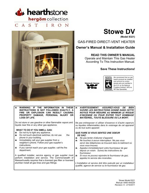
<strong>Hearthstone</strong> Quality Home Heating Products, Inc. <strong>Stowe</strong> Model <strong>8321</strong>SPECIFICATIONSLISTED: Gas-Fired Direct-Vent Fireplace HeaterModel: <strong>Stowe</strong> Direct-Vent Gas Fireplace Heater (<strong>8321</strong>)Testing Agency: Intertek Testing Services NA, Inc. (ITS)Tested to: ANSI Z21.88-2002, CSA 2.33-M02, CAN/CGA2.17-M91Certified for Canada, CSA P.4.1Approved for Mobile Home Installation (see page 5)Figure 1: <strong>Stowe</strong> <strong>8321</strong> DimensionsSPECIFICATION: NG LPINPUT RATING (Btu/hr) 0-2000 ft 26,000 26,000INPUT RATING (Btu/hr) 2000-4500 ft 25,500 25,500ORIFICE SIZE (DMS) 0-2000 ft 40 53ORIFICE SIZE (DMS) 2000-4500 ft 41 54MANIFOLD PRESSURE - LO SETTING (in. W.c./kpa) 1.2/0.3 3.3/0.8MANIFOLD PRESSURE - HI SETTING (in. W.c./kpa) 3.5/0.87 10.0/2.48INLET PRESSURE - LO (in.w.c./kpa) 5.0/1.24 11.0/2.88INLET PRESSURE - HI (in.w.c./kpa) 7.0/1.74 13.0/3.22MINIMUM INPUT RATING (btu/hr) 15,600 15,600MAXIMUM OUTPUT (btu/hr) 0-2000 ft 18,100 18,1006
<strong>Hearthstone</strong> Quality Home Heating Products, Inc. <strong>Stowe</strong> Model <strong>8321</strong>OWNER’S INFORMATIONThe installation must conform with local codes or, inthe absences of local codes, the current NationalFuel Gas Code, ANSI Z223.1 (NFPA 54) orCAN/CGA B149 Installation Code. (Installerl’appareil selon les codes ou règlements locaux, ou,en l’absence de tels règlements, selon les Codesd’installation CAN/CGA-B149.)Do not use this appliance if any gas controlpart was under water. Immediately call aqualified service technician to inspect theheater, and to replace any part of the controlsystem and gas control that was submerged.(Ne pas se servir de cet appareil s’il a étéplongé dans l’eau, complètement ou en partie.Appeler un technicien qualifié pour inspectorl’appareil et remplacer toute partie du systèmede contrôle et toute commande qui ont étéplongés dans l’lau.)DAILY OPERATIONThe <strong>Stowe</strong> gas-fired heater is operated easily by thehomeowner once it is installed and adjusted byqualified service personnel. The unit is controlled viathe wall-mounted thermostat during the heatingseason. Set the thermostat to the desired roomtemperature and the unit will cycle on and off asrequired. By adjusting the variable output controllocated on the gas control valve, the rate of heatoutput can be varied to meet the heatingrequirements of the season. Choosing a low flamesetting will result in longer burn cycles at a reducedoutput, while choosing a high flame setting will resultin a shorter, hotter burn cycle. Through trial anderror, the homeowner can select the optimum flamesize for their setting, and application.EFFICIENCYDuring the summer non-heating season, switch thewall thermostat to “OFF”, and turn off the pilot byturning the gas control to “OFF”. This will improvethe overall efficiency of the unit as the heat from thepilot is wasted. When putting the unit back intoservice, follow the lighting instructions described onpage 28.CONDENSATIONWhen burned, fuel gasses produce Carbon Dioxide+ Carbon Monoxide + Carbon + Water. So, when theunit is first lit, especially when cool, it is normal toexperience some water condensation on the insideof the window glass. This condensation willevaporate within the first few minutes of operation. Ifcontinuous condensation is observed on the windowglass, or dripping water is seen coming from anypart of the unit or venting system (chimney),immediately discontinue operation of the unit, andcontact qualified service personnel.7
<strong>Hearthstone</strong> Quality Home Heating Products, Inc. <strong>Stowe</strong> Model <strong>8321</strong>CODESAdhere to all local codes or, in their absence, thelatest edition of THE NATIONAL FUEL GAS CODEANSI Z223.1 (NFPA 54) or CAN/CGA B149Installation Code that can be obtained from:AMERICAN NATIONAL STANDARDS INSTITUTE, INC.1430 BROADWAYNEW YORK, NY 10018www.ansi.orgORNATIONAL FIRE PROTECTION ASSOCIATION, INC.BATTERY MARCH PARKQUINCY, MA 02269www.nfpa.orgThe appliance when operated with a blower installedmust be electrically connected and grounded inaccordance with local codes or, in the absence oflocal codes, with the current NFPA 70-NationalElectrical Code or CSA C22.1-Canadian ElectricCode.A manufactured home (mobile) OEM installationmust conform to the Manufactured HomeConstruction and Safety Standard, Title 24 CFR,Part 3280 (U.S.) or Standard for ManufacturedHome Installation, ANSI/NCBCS A225.1 or Standardfor Gas Equipped Recreational Vehicles and mobileHousing, CSA Z240.4.CAN/SCA Z240 MH(Canada). (Installer l’appareil selon les codes ourèglements locaux, ou, en l’absence de telsrèglements, selon les Codes d’installationCAN/CGA-B149.)For installations from 610-1370 meters (2000-4500ft.) the orifice sizes (DMS) for natural and propanegas are 41 and 54 respectively. See data plate foradditional information. For high altitude installationsconsult the local gas distributor or the authorityhaving jurisdiction for proper rating methods. If theinstaller must convert the unit to adjust for varyingaltitudes, the information sticker must be filled out bythe installer, and adhered to the appliance at thesame time of conversion. (Cet appareil est equipèpour des altitudes compries entre 0 et 2000 pieds(0-610 m) seulement.)ITEMS REQUIRED FOR INSTALLATIONExternal regulator (for propane/L.P.G. only)Piping which complies with local codesPipe sealant approved for use withpropane/L.P.G. (resistant to sulfur compounds)INSTALLER’S INFORMATION<strong>Manual</strong> shutoff valveSediment trap (see page 23)Tee jointPipe wrenchPhillips head screwdriver7/16-inch wrenchOther parts as required by local codeSafety GlassesGlovesPACKING LIST1-<strong>Stowe</strong> Gas-Fired Heater4-Decorative Ceramic Logs1-Bag Charcoal Embers Only1-Bag Charcoal Embers1-Bag Platinum Bright Embers1-Owner’s <strong>Manual</strong>1-Thermostat1-40’ Thermostat wire1-L.P. Fuel Conversion Kit1-Warranty Validation Form1-Exhaust Restrictor Plate with Mounting Screw2- Decorative CapsThe two screws holding the top of the fronton are for shipping purposes only. Once thestove has arrived at the final destinationremove these two screws and replace themwith the two decorative caps provided withthe unit.Note: Vent kits and components are suppliedseparately. Failure to use the ventingcomponents suggested by <strong>Hearthstone</strong> willvoid your warranty.UNPACKING AND INSPECTIONThe <strong>Stowe</strong> is packaged by <strong>Hearthstone</strong> to withstandnormal shipment without damage. However,damage can still occur during transit; so take care toinspect for damage when unpacking and installingthe unit. If any damage or missing parts aredetected, immediately contact your dealer.DO NOT INSTALL, OR PUT INTO SERVICE, ADAMAGED OR INCOMPLETE HEATER.CAUTION: THE TOP GRILL IS NOT CEMENTED,OR OTHERWISE PERMANENTLY FASTENED INPLACE!We recommend your <strong>Stowe</strong> be moved into place,venting attached, gas and electrical connections8
<strong>Hearthstone</strong> Quality Home Heating Products, Inc. <strong>Stowe</strong> Model <strong>8321</strong>made, and any accessory blower installed beforeinstalling the top grille.Inspect the <strong>Stowe</strong> for visible or concealed damage.The unit should appear to be square and true. Thesheet metal parts should be smooth and free ofbends and dents. The enameled cast iron should befree of chips or cracks. If visible or concealeddamage is found, or suspected, contact your dealerfor instructions.With the accessory box removed and set aside,undo the lag bolts that fasten the unit to the pallet.Take care not to mar or chip the enameled legs.Have someone help lift the stove off the pallet andset it into place.The decorative ceramic logs supplied with the <strong>Stowe</strong>are contained within the firebox. Always use greatcare when handling the decorative ceramic fire logs,as they are fragile and subject to damage andbreakage if handled roughly. Open the firebox doorand inspect the logs for damage. If a broken log isencountered, contact your dealer for replacementlogs. Otherwise, set the logs aside until called forduring the installation.FIREBOX ACCESSTo open the firebox:1. Remove the two upper front screws (located inthe grill of the front) that hold the cast façadeonto the unit. (These screws ship on the unitfor transit purposes only and are removedduring installation.)2. Open the valve access door by pulling the ashlip out off the magnet and down. Allow the doorto swing down completely.CatchL-Bracket (2)Latch HandleFigure 2: Façade Spring Latch Detail3. Grasp the handle of the spring latch, located inthe center of the opening, pull out towards youand then move the handle to the right todisengage the catch, then release tension on thelatch - be careful not to drop the front as thelatch is unfastened. Be careful not to chip theenamel when handling the front façade.4. Grasp the bottom of the façade, lift it up slightlyand out off the L-brackets. Lower the façade andmove it away from the unit - set aside5. To remove the glass, reach over the firebox, andunder the front grill. With a flat screwdriver, prythe retaining clips up. There are two separateclips. Be careful, when you lift the last one, as itwill free the glass and frame from the unit.Note: The two screws holding the top of the fronton are for shipping purposes only. Once the stovehas arrived at the final destination, remove thesetwo screws and replace them with the twodecorative caps provided with the unit.6. To re-install – reverse the outlined steps above.HEARTH & FLOOR PROTECTIONThe <strong>Stowe</strong> may be placed on any non-combustiblesurface or wood floor. For placement of the <strong>Stowe</strong>on carpeting, vinyl tile or other combustiblematerials, the appliance must be installed on a metalor wood panel extending the full width and depth ofthe appliance. Installations must meet local codes.CLEARANCE TO COMBUSTIBLESDue to high surface temperatures, the unit should belocated out of traffic, and away from furniture anddraperies. Clothing and other flammable materialshould not be placed on or near the heater. Whenpositioning the unit always maintain adequateclearances around air openings into the combustionchamber and allow for adequate ventilation.Minimum clearances to combustibles must bemaintained as shown in figures 3 through 7.Note: The rear clearance to combustibles isdetermined by either the unit’s, or the vent pipe’sminimum clearance, depending on whether theinstallation calls for vertical rise within the roomor a rear exit, through-the-wall vent pipe.Ensure you consider the need for access to the gascontrol valve access door on the front of the unit aswell as full access for periodic cleaning andservicing. Also consider the location of the OptionalBlower Fan.9
<strong>Hearthstone</strong> Quality Home Heating Products, Inc. <strong>Stowe</strong> Model <strong>8321</strong>CAUTION: THESE CLEARANCES REPRESENTMINIMUM DISTANCES IN ALL CASES, WHICH,THROUGH TESTING IN AN INDEPENDENTLABORATORY TO ANSI AND CSA STANDARDS,WILL PREVENT FIRE OR SPONTANEOUSCOMBUSTION. WE DO NOT CONTROL THECOMBUSTIBLE MATERIALS EXPOSED TO HEATBY THIS PRODUCT; THEREFORE, ANASSESSMENT MUST BE MADE BY THEINSTALLER TO PREVENT CONSEQUENTIALDAMAGE OF WALLS AND FLOORING.THE CORNER CLEARANCE FOR THE STOWE IS2”, TO BE MEASURED FROM THE EDGE OF THETOP CASTINGS, TO THE ADJACENT WALL.Figure 5: Snorkel-Mantle Clearance toCombustiblesFigure 3: Minimum Venting-Mantle Clearance toCombustiblesFigure 6: Snorkel-Wall Clearance toCombustiblesFigure 4: Minimum Venting-Wall Clearance toCombustiblesFigure 7: Minimum Alcove Dimensions10
<strong>Hearthstone</strong> Quality Home Heating Products, Inc. <strong>Stowe</strong> Model <strong>8321</strong>VENTING CONNECTIONNote: Starter collar is installed by <strong>Hearthstone</strong>.1. The <strong>Stowe</strong> Direct Vent is approved forinstallation only with the vent connectingcomponents listed on this page and SimpsonDura-Vent Direct Vent GS, AmeriVent Direct,EXCELDirect or Secure Vent systems. Use thefollowing instructions along with the pipemanufacturer’s instructions to complete theinstallation.2. To attach the Restrictor Plate; see instructionsincluded with it. It will attach from inside thefirebox, after removal of the brick patternedbaffle. The two screws required are included inthe appliance. Be sure you can see the screwhead for future adjustments.Note: For minimum venting configurations,discard the restriction plate- see section“Approved Vertical Termination VentingConfigurations”3. Install the rest of the vent system according tothe manufacturer’s instructions.VENTING INFORMATIONFigure 7: Key1. Restriction Plate 5950-9222. Gasket 4” 3160-1553. Inner starter 924H14. Gasket 6” 3160-1575. Outer Starter 924H1Figure 9: Gasket & Stove Adapter InstallationFigure 9: Starter collar and Restriction Plateassembly12
<strong>Hearthstone</strong> Quality Home Heating Products, Inc. <strong>Stowe</strong> Model <strong>8321</strong>RESTRICTION PLATEThe restriction plate is used to control the draft of theheater. Controlling the draft also changes theaesthetics of the flame. The restriction plate haseight settings, one (1) being the lowest and eight (8)being the highest. For a fast moving flame with lotsof action, use a low setting. For a slow, lazy flame, ahigh setting should be used. See Figure 11 forinstructions on how to adjust the restriction platesettings.RESTRICTION PLATE POSITIONA vent restriction plate is available for the applianceto adjust the flow rate of exhaust gases. This insuresproper flames for the wide variety of ventconfigurations, and efficiency. The restriction plateconsists of a rotating shutter below the startersection of pipe and an adjustment plate with indexholes used to hold the shutter in a fixed position.Depending on the vent configuration, you may berequired to adjust the restriction plate position. Referto figures 12 - 15 for positioning of the restrictionplate.ADJUSTMENT TO RESTRICTION PLATERemove the log set before adjusting the restrictionplate by following the log set removal instructions onpage 25. Make sure the unit is cool before touchingany part of the firebox and log set. Remove theexhaust baffle by removing the one screw in thecenter of the baffle (refer to Figure 8). The baffle willcome out once the screw is removed. Be careful notto drop the baffle on the pan burner. Once the baffleis set aside, check the restriction plate screwlocation. There are eight locations that the restrictionplate can be positioned. (Refer to VentingConfiguration – Figures 14 – 16 for recommendedrestriction plate positions) (Refer to Figure 11 forproper adjustment plate index location) ‘A’ in Figure11 shows the locating screw that determines theposition of the plate.NOTE: These positions are based on labresults and can have some variance.Remove the screw and position the restriction platein the desired location. Fasten the screw into theproper hole and tighten. Reinstall the exhaust baffleby setting the back edge of the baffle into the baffleclip attached to the back wall of the firebox. Thenpush the baffle against the heat exchanger andreinstall the screw. Reinstall the log set and emberstrip as described in the log set installationprocedure on page 25.Figure 10: Baffle RemovalFigure 11: Restriction Plate AdjustmentsVENTING COMPONENTS &CONFIGURATIONThe <strong>Stowe</strong> cannot be vented jointly with any othersolid fuel or gas appliance. It must be vented directlyto the outside of the building using a propertermination as listed in the manual. The only type ofventing pipe approved for use with your <strong>Stowe</strong>Direct-Vent stove is Simpson Dura-Vent’s GS,AmeriVent Direct, EXCELDirect and Secure VentDirect-Vent Pipe. The venting configurations areshown in Figures 12 - 17. After determining theventing configuration for your stove, select the ventsystem that will accommodate your installation.CAUTION: ENSURE ALL STOVE ANDTERMINATION CAP CLEARANCES AREOBSERVED PER THE OWNER’S MANUAL.13
<strong>Hearthstone</strong> Quality Home Heating Products, Inc. <strong>Stowe</strong> Model <strong>8321</strong>CAUTION: ENSURE THERE IS NO WIRING ORPLUMBING IN THE CHOSEN LOCATION.CAUTION: VENTING TERMINALS SHALL NOT BERECESSED INTO A WALL OR SIDING.Note: If further direction is needed forinstallation, please refer to the ventinginstructions, which are provided with the ventingcomponents.ACCEPTABLE DIRECT-VENT TERMINATION CAPLOCATIONSThe vent/air intake termination clearances above thehigh side of an angled roof are as follows:Roof Pitch Feet MetersFlat to 6/12 1 0.37/12 to 9/12 2 0.610/12 to 12/12 4 1.213/12 to 16/12 6 1.817/12 to 21/12 8 2.4Listed are Simpson Dura-Vent, AmeriVent Direct,EXCELDirect and Secure Vent componentsacceptable for installation, along with the minimumventing kit available. The venting system must becomprised of the appropriate venting components asspecified.APPROVED VENTING SYSTEM COMPONENTS90 0 Elbow45 0 Elbow6" Straight9" Straight (Simpson only)12" Straight24" Straight36" Straight48" Straight11"-14 5/8" Adjustable Pipe LengthHorizontal Vent CapVertical Vent Cap14” SnorkelVinyl Siding Standoff 4 x 6 5/8"Round Ceiling Support WallThimble CoversWall thimbleCHIMNEY LINER SYSTEM1. Direct-Vent Chimney Liner Termination Kit2. Chimney Liner Flex3. Co-Linear Flex Connector4. Co-Axial to Co-Linear Appliance ConnectMINIMUM VENT KIT*<strong>Hearthstone</strong> Stove Starter Collar45º Elbow90º Elbow(2) 9” StraightRound Ceiling SupportWall Thimble CoverWall ThimbleHorizontal Vent Cap*Supplied and pre-installed by <strong>Hearthstone</strong>14
<strong>Hearthstone</strong> Quality Home Heating Products, Inc. <strong>Stowe</strong> Model <strong>8321</strong>Any centerlines shown are approximate. Please dry fit your venting and take measurements. Pipedimensions will vary by manufacturer and supplier.See installation instructions on page 20.Figure 12: Components for a Typical SnorkelInstallationFigure 13: Components for a Typical MinimumHorizontal Venting InstallationAPPROVED VERTICAL TERMINATION VENTING CONFIGURATIONS**With No Elbows or (2) 45º Offsets (Figure 14), and (2) 90º Elbows (Figure 15)10’ minimum system height (with or without offsets)35’ maximum system height6’ maximum offset (refer to Figure 14)12’ maximum offset (refer to Figure 15)The termination must fall within the outline shown in Figures 14 & 15. Use the indicated restriction plateposition. The restriction Plate part # is 5950-922.PIPE CLEARANCES TO COMBUSTIBLES1” to vertical runs1” below and to the side of horizontal runs2” from the top of horizontal runs15
<strong>Hearthstone</strong> Quality Home Heating Products, Inc. <strong>Stowe</strong> Model <strong>8321</strong>Figure 14: Vertical Straight Pipe Terminations16
<strong>Hearthstone</strong> Quality Home Heating Products, Inc. <strong>Stowe</strong> Model <strong>8321</strong>APPROVED VENTING CONFIGURATION FORHORIZONTAL TERMINATION**(1) 90º ElbowThe termination must fall within the area outlinedby the shaded area shown in the illustrationbelow.A minimum of a 9” rise is required directly off theheater.Use a vinyl siding standoff when installingagainst vinyl siding.Horizontal sections require a ¼” rise every 12” ofhorizontal run.NOTES:1. The vent must terminate within one of theregions outlined by the shaded area.2. For each 90º elbow after 2, remove 5’ fromhorizontal run.3. For Canadian installations: remove 4’from horizontal run.4. At minimum vertical rise, maximumhorizontal run 14”.5. Use with snorkel termination 14” maximumhorizontal run.Figure 16: Horizontal Termination18
<strong>Hearthstone</strong> Quality Home Heating Products, Inc. <strong>Stowe</strong> Model <strong>8321</strong>APPROVED CONFIGURATION FOR FIREPLACE INSTALLATIONThe termination must fall within the demarcation line shown in the illustration. Use the indicatedrestriction plate position. Restriction plate # 5950-922.Figure 17: Co-linear & Chimney as an AIR INLET19
<strong>Hearthstone</strong> Quality Home Heating Products, Inc. <strong>Stowe</strong> Model <strong>8321</strong>STANDARD HORIZONTAL TERMINATIONMINIMUM VENTING KITInstallation Instructions for Kit #97-650011. The starter collar is factory installed. Determineif you need a Restriction disc, and install ifnecessary.2. Install the 45º elbow over the outer collar. Placethe elbow so that the twist lock end is pointingup.3. Install one of the 9” pipe sections into the elbowby fully inserting it and turning approximately ¼turn clockwise, until the 2 sections are fullylocked. Install the 90º elbow in similar fashion.4. Move the stove and pipe assembly back until the90º elbow is flush to the wall. The 9” vertical pipeshould be parallel to the wall. Draw a circlearound the pipe. Use the center of this circle asthe center point of the 10” x 10” square wallpass through. Cut and frame the wall passthrough.5. Place the interior wall thimble into the 10” x 10”wall pass through. Secure it with 4 screws (notprovided). Install the exterior portion of thethimble in similar fashion, overlapping the 2sections.CAUTION: FOR BUILDINGS WITH VINYL SIDING,A VINYL SIDING STANDOFF MUST BEINSTALLED BETWEEN THE VENT CAP AND THEEXTERIOR WALL.6. Install the horizontal vent termination on theoutside of the wall. Make sure both of theretaining straps extend through interior wallthimble. Before attaching the vent termination tothe outside of the house, run a bead of nonhardeningmastic around its’ outside edges, soas to make a seal between it and the wall. Thearrow on the end cap should point up. Securethe cap to the wall with the appropriate screws.7. Place the thimble cover onto the 90º elbow. Putthe 9” pipe into the horizontal vent cap, (the ventpipe must extend into the horizontal vent cap aminimum of 1-1/4”). Move the stove and ventpipe into position, insert the 9” pipe into the 90ºelbow and twist to lock it. Secure the straps fromthe horizontal vent termination to the interiorpipe with 2 sheet metal screws, keeping screwsclose to wall thimble as possible. Bend or cut theexcess strapping so that the thimble cover will fitproperly. Screw the thimble cover to the wall.20
<strong>Hearthstone</strong> Quality Home Heating Products, Inc. <strong>Stowe</strong> Model <strong>8321</strong>WIRING DIAGRAMFigure 18: Wiring Diagram22
<strong>Hearthstone</strong> Quality Home Heating Products, Inc. <strong>Stowe</strong> Model <strong>8321</strong>GAS SUPPLY & CONNECTIONSNOTE: If the optional blower is installed now or in the future, ensure the gas line is installed as close to thefloor as possible.NOTICE: A qualified technician must connect theheater to the gas supply and leak test the unitbefore it is approved for use. Consult all codes.WARNING: The unit must be installed andconnected in accordance with local codes, or inthe absence of local codes, with the most currentedition of the National Fuel Gas Code ANSI Z223.1(NFPA 54) or CAN/CGA B149 Installation Code.Gas SupplyInletFigure 19: Gas Control Valvethe lack of a sediment trap are not covered bywarranty.GAS CONNECTIONSThe gas supply connection is made to the <strong>Stowe</strong>’sgas control valve just inside the left front leg of theunit using a 3/8” male NPT fitting. The supply lineshould be ½” diameter, or appropriately sized toprovide a sufficient gas supply to meet the maximumdemand of the unit without undue loss of pressure.We recommend a flexible line to avoid unduemechanical load on the valve and to ease threadalignment, but refer to local codes.CAUTION: CHECK GAS TYPE!To EquipmentInletNippleCapTee Fitting3" MIN.Figure 20: Sediment Trap (Typical)NFPA Code and <strong>Hearthstone</strong> require the use of adedicated sediment trap just upstream of the unit.Damage to the valve, or other components due toGAS SUPPLYThis appliance and its individual shutoff valve mustbe disconnected from the gas supply piping systemduring any pressure testing of that system at testpressures in excess of ½ psig. The <strong>Stowe</strong> must beisolated from the gas supply piping system byclosing its individual manual shutoff valve during anypressure testing of the gas supply piping system attest pressures equal to or greater than ½ psig.23
<strong>Hearthstone</strong> Quality Home Heating Products, Inc. <strong>Stowe</strong> Model <strong>8321</strong>GAS PRESSURE ADJUSTMENTNOTE: A QUALIFIED TECHNICIAN MUSTPERFORM THIS PROCEDURE!Once connected to the gas supply, the supply lineand manifold gas pressures must be tested. Thesupply line pressure is tested to ensure it meets theminimum gas supply pressure as listed in thespecifications for the type of fuel in use (natural gasor LP). Connect a manometer to the supply line andadjust the incoming pressure if necessary to meetthe required supply line pressure as listed inspecifications. The manifold pressure tap on the gascontrol valve, refer to Figure 19 for location.24
<strong>Hearthstone</strong> Quality Home Heating Products, Inc. <strong>Stowe</strong> Model <strong>8321</strong>CAUTION: FRAGILE! HANDLE LOG SETWITH CARE. ALWAYS WEAR GLOVES ANDSAFETY GOGGLES WHILE HANDLING THE LOGSET.Only the decorative ceramic log set supplied with theunit should be placed in the firebox. Do not placeany other ceramic logs, wood logs, or othermaterials in the firebox. If the log set is damaged orbroken contact your dealer for replacement. Thedecorative ceramic log set will last a long time;however, they will break if subjected to rough orimproper handling. Exact positioning of the log set isrequired in order to obtain a pleasing flame patternand efficient combustion. Incorrect log placementmay cause carbon build-up; excess thermal stresson the log set and stove parts, reduced efficiency,and high levels of carbon monoxide. If the log setdoes not set into the firebox exactly as outlined,contact your dealer for assistance.LOG PLACEMENT5. Gently slide the “Cordwood” style log (2)onto the Rear post and the Left post, withthe rear portion of the log on top of theForked Log (1).INSTALLING THE LOG SET(Refer to the following images in this section for logset assembly)1. See page 9 for firebox access instructions.2. Pull off the glass frame by prying up the twometal clips on top of the firebox. Once theseare pulled up, the frame can be pulled awayfrom the firebox, and off the stove.3. Remove the packaging material around thelog set assembly. Be careful not to damagethe log set when unpacking. Observe the 4mounting “posts”, Right, Rear, Left, andFront.6. Gently slide the Straight Log (3) onto theRight post and the Front Post, with theCharred end towards the front.4. Gently slide the Forked Log (1) onto theRight post and the Rear post, with the forkedend toward the front right of the firebox.25
<strong>Hearthstone</strong> Quality Home Heating Products, Inc. <strong>Stowe</strong> Model <strong>8321</strong>7. Gently place the Top Log (4) in theindentation on the Cordwood Log (2) andthe pilot assembly, being sure to slide theend into the rear corner of the firebox.9. Replace the glass frame by sliding it downthe face of the firebox and pushing the topback. Slide the two clips back down to holdthe frame in place.8. Spread the Charcoal Embers evenly acrossthe Pan Burner, one layer high. You may,or may not, need to use all of the CharcoalEmbers. Keep the remainder to use in thefuture. Do not block the air opening undercast brick panel in any way. Locate andopen the bag of Platinum Bright Embers.Pull apart small pieces of the wool andsprinkle over the Charcoal Embersrandomly. This wool will glow once the unitis running.REMOVAL OF LOG SETCAUTION: THE LOG SET AND CHARCOALEMBERS RETAIN HEAT AND CAN BE VERY HOT!ALLOW 2 TO 3 HOURS AFTER PILOT LIGHT ISTURNED OFF BEFORE HANDLING.To remove the log set, follow the Installation of LogSet instructions in the reverse order.26
<strong>Hearthstone</strong> Quality Home Heating Products, Inc. <strong>Stowe</strong> Model <strong>8321</strong>INITIAL OPERATION PREPARATIONWARNING: IF YOU DO NOT FOLLOW THESEINSTRUCTIONS EXACTLY, A FIRE OREXPLOSION MAY RESULT CAUSING PROPERTYDAMAGE, PERSONAL INJURY OR LOSS OF LIFE.CAUTION: LIGHTING THE STOWE FOR THE FIRSTTIME AND ADJUSTMENTS TO THE UNIT SHOULDBE PERFORMED BY QUALIFIED SERVICEPERSONNEL.SMOKE AND FUMES WARNINGWhen lit for the first time, the <strong>Stowe</strong> will emit somesmoke and fumes. This is normal “off-gassing” ofthe paints and oils used in the manufacturing andassembly of the unit. Open windows to vent theroom if necessary. The off gassing and fumes willsubside after the first 10 to 20 minutes of operation.BREAK-IN WARNINGThe cast iron and cement used in the assembly ofthe <strong>Stowe</strong> must be heated up slowly to avoiddamaging it. This is accomplished by adhering to thefollowing break-in procedure.BREAK-IN PROCEDUREWhen lit the first time, the <strong>Stowe</strong> should be burnedfor no more than 15-30 minutes, and then allowed tocool for 1 hour. This gentle warming and cooling ofthe unit will allow the cast iron and cement to cureproperly. Once this break-in procedure has beencompleted, the <strong>Stowe</strong> can be burned at will with notime restrictions on the length of burn.ODORS AND IMPURITIESA heater of this type may produce odors duringheater operation due to impurities that may exist inthe immediate area. Sources of impurities can becleaning solvents, paint solvents, cigarettes,candles, smoke, pet hair, dust, adhesives, newcarpet, and/or textiles. Such odors will dissipate.However, opening a window or otherwise providingadditional ventilation to the area can alleviate thecondition. If any odor persists, contact your dealer oran authorized service technician.PILOT LIGHT WARNINGThe <strong>Stowe</strong> has a piezoelectric spark igniter (the redpush button located next to the gas control valvebehind the valve access door), which ignites the pilotlight by means of a spark at the pilot light assembly.Do not attempt to light the unit with a match or byany means other than the piezoelectric spark.PREPARE FOR LIGHTINGPrepare for the lighting procedure by adjusting thethermostat (if equipped) to its lowest setting or OFFposition. If the gas control knob is not in the OFFposition, turn the knob fully clockwise to OFF. Locatethe variable output control knob and turn it fullyclockwise to the highest setting.Prior to lighting the unit for the first time, wait 5minutes to allow any residual gas within the unit todissipate. Smell all around the appliance area forgas. Be sure to smell next to the floor because somegases are heavier than air and will settle on thefloor. If you do not smell gas after this five-minuteperiod, proceed with the lighting procedure. If you dosmell gas, DO NOT proceed with the lightingprocedure. Instead, immediately refer to the WhatTo Do If You Smell Gas Warning, on the cover ofthis manual.WARNING: THE VALVE CONTROL HAS ANINTERLOCK DEVICE. AFTER SHUTTING OFF ALLGAS FLOW, THE PILOT BURNER CANNOT BERELIT UNTIL THE THERMOCOUPLE HASCOOLED, ALLOWING THE ELECTROMAGNET TOBE RELEASED (APPROX. 60 SECONDS). THEGAS CONTROL KNOB IS DESIGNED TOOPERATE BY HAND. DO NOT USE ANY TOOLSDURING THIS OPERATION. DAMAGED KNOBSMAY RESULT IN SERIOUS INJURY.27
<strong>Hearthstone</strong> Quality Home Heating Products, Inc. <strong>Stowe</strong> Model <strong>8321</strong>LIGHTING INSTRUCTIONS & INITIAL ADJUSTMENTSOnce the <strong>Stowe</strong> is set in place, connected andassembled as described in the Clearances ToCombustibles, Venting Components &Configurations, Electrical Connections, And GasSupply and Connections sections of this manual, theunit is almost ready to be lit for the first time. Themanufacturer tests each unit prior to shipment, soignition should take place without failure. However, anumber of small adjustments may be necessary tocompensate for variations in gas pressure, altitude,and other factors particular to each installation.VARIABLE OUTPUT CONTROLThe gas control valve is equipped with a variableoutput control. This control varies the rate of heatproduced by the unit by varying the gas pressure tothe pan burner. A combination of heat output andthe thermostat setting affect the length of the burncycle. If your stove turns on and off too often, try,first, reducing the burn cycle by turning the HI/LOWknob, on the control valve, to a lower setting. Usingthe variable output control, the heat output of theunit can be reduced for mild fall and spring months,or maximized for the colder winter months. Thisadjustment can be made, by the homeowner, asnecessary by turning the variable output controlknob to “HI”, “LO” or any setting in between.AIR SHUTTERThe air shutter is used to regulate the air-to-gascombustion mixture, which in turn influences the sizeand color of the flames. The air shutter is positionedin the general location needed for the type of gasbeing used, however, if the unit is not burning aswell as it should, then the air shutter may needadjusting. The air shutter may need adjustment oncethe unit has been installed to compensate forvariations in supply line pressure, restriction plateposition, altitude, gas type conversions, and othervariables.To determine if the air shutter needs adjustment, it isnecessary to view the flame pattern with the variableoutput control knob at its highest setting. Allow theunit to operate for at least 10 minutes to allow theentire unit to reach temperature, and for the flamepattern to stabilize. Generally, the more air (openshutter) in the mixture, the bluer the flame. Less air(closed shutter) results in a more yellow flame, buttoo little air will result in incomplete combustion, lowefficiency and a dirty burn. There are two simpleguidelines to aid in determining the correct flamepattern:1. If the flame at the base of the logs iscompletely blue, the air shutter may be opentoo far;2. If the flame is dirty or licks the top of thestove, the air shutter may be closed too far.Some conditions cannot be corrected through airshutter adjustment; an adjustment must be made tothe gas supply pressure or by changing therestriction plate location. Qualified service personnelmust perform supply line/manifold gas line pressureadjustments and restrictor plate adjustments. Do notattempt to complete any part of the installation oradjustment of this unit unless technically qualified todo so.LIGHTING INSTRUCTIONSNOTE: The gas control knobs and the Piezoigniter are located behind the control valveaccess door, under the front of the unit.1. STOP! Read the What To Do If You Smell Gas!Warning (on the cover of this manual).2. Set the on/off/T’stat switch or thermostat to the“OFF” position.3. Unplug the blower accessory, if so equipped.4. Push in and turn gas control knob clockwise to“OFF”. (If not previously lit, the knob should bein this position.)5. Wait (5) five minutes to clear out any gas. If youthen smell gas, STOP! Smell all around theappliance area for gas. Be sure to smell next tothe floor because some gases are heavier thanair and will settle on the floor. If you smell gasimmediately follow the What To Do If YouSmell Gas! warning on the cover of this <strong>Manual</strong>.If you do not smell gas, proceed to the next step.6. Turn gas control knob counter-clockwise to“PILOT”.7. Push in control knob all the way and hold in.Immediately light the pilot with the gas lighter(push in and “click” the piezoelectric sparkigniter button several times until lit). Continue tohold the control knob in for about 20 secondsafter the pilot is lit. Release the knob and it willpop back out. Pilot should remain lit. If the pilotgoes out, repeat the operation.If knob does not pop out when released,stop, shut off the gas supply to the heaterand immediately call a qualified servicetechnician or gas supplier.28
<strong>Hearthstone</strong> Quality Home Heating Products, Inc. <strong>Stowe</strong> Model <strong>8321</strong>If the pilot will not stay lit after several tries, turnthe gas control knob “OFF” and call a qualifiedservice technician or gas supplier.8. After the pilot lights, turn gas control knobcounter-clockwise to “ON”.9. If the ON/OFF/T’stat switch is set to “ON”, thestove should now be lit. If the thermostat (orremote) has been installed, set the ON/OFF/T’stat switch to “T’stat” and turn the thermostat(or remote) to “ON”. Then set the desiredtemperature.10. Shut the gas control valve access door.11. Plug in the fan accessory, if so equipped.12. If T’stat was selected, set thermostat to “ON”and set desired temperature setting. Normally, ifT’stat position was selected, the main burner iscycled on and off by the thermostat or the“on/off” switch located on the bottom of thethermostat body.NOTE: When pressing/clicking the piezoelectricspark ignition button to light the pilot, watchthrough the glass (front) of the unit. Click theigniter button until a flame is visible at the pilot.Once the pilot is lit, continue to press on the gascontrol knob for another 20 seconds, thenrelease. Ascertain that the pilot is still lit bylooking through the front door. If lit, then turn thegas control knob fully counter-clockwise to the“ON” position. If the pilot fails to light, or if it wentout due to a premature release of the gascontrol knob while depressed in the “PILOT”position, wait 60 seconds for the Interlock torelease. Then repeat the lighting process asdescribed in this section of the manual.Once the pilot is lit, the gas control knob is turned tothe “ON” position, and the ON/OFF/T’stat switch isturned to “ON”, the main burner should lightimmediately. If you would like to use the thermostatand it has been installed, switch the ON/OFF/T’statswitch to thermostat. Turn the thermostat to "ON"and set it to a higher position so that it "calls" forheat in order to light the main burner (i.e. turns theunit on). Note that the thermostat controls the on/offcycling of the main burner, but the pilot remains litregardless of the thermostat setting. The only way toturn the pilot off is to turn the gas control knob fullyclockwise to the “OFF” position.clockwise to the “OFF” position. Do notforce the knob to turn.AIR SHUTTER ADJUSTMENTSThe air shutter, located at the lower rear center ofthe stove, is adjustable while the stove is burning byloosening the set nut on the adjusting bolt located onthe lower rear left of the stove. This nut is hot andshould not be touched. Use only metal tools for thisadjustment. Loosen the set nut and turn the bolt toadjust the flame pattern. Turn the bolt clockwise toopen the air shutter, and counterclockwise to closethe shutter. When the flame pattern is correct,tighten the set nut without letting the bolt turn. Theair shutter is factory set and only a qualified gastechnician should make adjustments.Note: Very little movement is needed tosubstantially change the burn and flamepatterns. Some conditions cannot be correctedthrough air shutter adjustment; an adjustmentmust be made to the gas supply pressure.Supply line/manifold gas line pressureadjustments must be performed by qualifiedservice personnel. Do not attempt to completeany part of the installation or adjustment of thisunit unless technically qualified to do so.PILOT ADJUSTMENTThe pilot light is preset by the manufacturer andshould not need adjustment. The pilot light flamemust be large enough to engulf the thermopile andthermocouple located next to the pilot, but not solarge as to create excessive noise or consumeexcessive gas. (Refer to page 30) However, it canbe adjusted by means of the pilot light adjustmentscrew located on the gas control valve. Open thevalve door to access the pilot adjustment screw.Note that the pilot flame must engulf the thermopileso that the thermopile can generate sufficientmilli-voltage (325 to 500-mv) to power the gascontrol valve. The flame on the pilot should look likeFigure 21. Controlling the <strong>Stowe</strong> by the wallmountedthermostat may become erratic,nonexistent, or the unit may go out, if the pilot flameis too small or misdirected away from the thermopile.TO TURN OFF GAS TO APPLIANCE1. Set the thermostat to the “OFF” positionor turn the ON/OFF/T-STAT switch tothe “OFF” position.2. If shutting the unit off for the non-heatingseason, turn the gas control knob fully29
<strong>Hearthstone</strong> Quality Home Heating Products, Inc. <strong>Stowe</strong> Model <strong>8321</strong>output control knob at its highest setting (turn fullyclockwise). Allow the unit to operate for 10 minutesenabling the entire unit and log set to reachtemperature and for the flame pattern to stabilize.The flame pattern should be similar to the oneshown in Figure 22. There are several guidelines toaid in determining if the flame pattern is correct:Figure 21: Pilot Flame PatternWARNING: THE CONTROL HAS AN INTERLOCKDEVICE. IF THE STOVE HAS BEEN LIT, IT WILLNOT RELIGHT IMMEDIATELY. AFTER SHUTTINGOFF ALL GAS FLOW, THE PILOT BURNERCANNOT BE RELIT UNTIL THE THERMOCOUPLEHAS COOLED, ALLOWING THEELECTROMAGNET TO BE RELEASED (APPROX.60 SEC.). THE GAS CONTROL KNOB ISDESIGNED TO OPERATE BY HAND. DO NOT USEANY TOOLS DURING THIS OPERATION.BURNER FLAME APPEARANCEOnce the unit is lit, observe the flame pattern andadjust as necessary. Also, perform a periodic visualinspection of the burner flame. The burner flame isadjustable by means of the air shutter. Todetermine if the burner flame needs adjustment, it isnecessary to view the flame pattern with the variable1. The flame must not be dirty, smoky, sooty, orlick the top of the stove.2. The flame must not rise off the pan burner; thisis called “lifting”.3. Flames must not impinge heavily on the log set.They should “fit” through the pre-formed spacesdesigned in the log set.Figure 22: Typical Burner Flame Appearance30
<strong>Hearthstone</strong> Quality Home Heating Products, Inc. <strong>Stowe</strong> Model <strong>8321</strong>ROUTINE MAINTENANCE & CAREThe <strong>Stowe</strong> requires minimal routine maintenanceand care. The unit should always be cool and offwhen being cleaned, or serviced.WARNING: DO NOT SUBSTITUTE MATERIALS.FOR REPLACEMENT PARTS, OR FORINFORMATION ABOUT PARTS OR SERVICE,CONTACT YOUR LOCAL HEARTHSTONEDEALER.CLEANING THE UNITWARNING: DO NOT CLEAN THE UNIT WHEN HOT.The unit should receive regular cleaning on, under,and around the stove to prevent the buildup of dustand lint. The exterior surfaces of the unit can becleaned using soap, water, and a soft cloth. Do notuse abrasive or chemical cleaners and take care notto scratch the glass or enamel finish (if so equipped)when cleaning the unit. The use of chemical waxbased cleaners or polishes are not recommendeddue to the potential for discoloration of the castingsor enamel when the residue of the cleaners orpolishes is exposed to heat. Excessive buildup ofdust, spider webs, or room air contamination maycause odors when the stove is hot.FIREBOX, PILOT, & BURNER ASSEMBLYThe firebox requires periodic cleaning to prevent theaccumulation of dust, lint, and other debris. To cleanthe firebox, set the thermostat to the “OFF” position,and turn off the gas at the gas control valve. Whenthe unit is cool, unfasten the front door and carefullyremove the decorative ceramic log set, taking carenot to damage the logs or chip the enamel cast iron.Remove all glowing ember material. Clean thefirebox pan burner, and carefully vacuum the entiresurface of the log set. Thoroughly vacuum the ports(holes) along the top of the pan burner, and the pilotassembly.With the decorative ceramic logs out of the firebox,fasten the door shut and briefly light the unitaccording to the lighting instructions described onpage 28. Check to insure a proper flame is burningfrom each burner port. The pilot flame should belarge enough to engulf the thermopile andthermocouple as shown in Figure 21.NOTE: Do not operate the unit for more than1-2 minutes without the log set in place. Turnthe unit off by setting the thermostat to“OFF”, and turning the gas control valve off.Allow the unit to cool.Check and clean any burner ports that are notburning, or not burning properly. Clean burner portsusing a soft brush or vacuum cleaner. If the pilotflame height needs adjustment, it should be adjustedby qualified service personnel as described on page29.Complete the cleaning procedure by carefullyplacing the log set within the firebox as described onpage 25. Close and fasten the front door. Turn onthe gas, light the unit and check for properoperation. Flame patterns should look similar to theflames in Figure 22. Regularly check to insure thearea around the <strong>Stowe</strong> is kept free from combustiblematerials, gasoline, and other flammable vapors andliquids. Check that the flow of combustion andventilation air is not obstructed. Once a year, theunit, and venting system should be inspected byqualified service personnel to ensure that theyare clean, free of obstruction, safe, and in goodworking order. If service or maintenance isrequired, qualified service personnel shouldperform it.FRONT DOOR GASKETYour <strong>Stowe</strong> uses a 3/4” flat tape-type fiberglassgasket to make a tight seal between the doorframeand the firebox. In time, the gasket can becomebrittle and compressed and should be replaced. Newgasket material is available from your Authorized<strong>Hearthstone</strong> Dealer. Protect your hands with workgloves, and wash up later.REPLACING THE DOOR GASKET1. Allow the <strong>Stowe</strong> to cool completely. Remove thecast iron front façade. Using a flat headscrewdriver lift up on the two clips above thefirebox. Be careful as you lift the second clip, theglass frame assembly will be loose to removefrom the unit2. Once you have the glass frame assembly freefrom the stove, remove the 1/8” rivet, by drillingit out with a 1/8” drill bit. Once the rivet isremoved pull the glass away from the frame.Remove the existing gasket by grasping oneend and pulling firmly.3. Use a glass cleaner to clean the surface of theglass to remove the remaining gasket.4. Determine the correct length of the appropriatesizedgasket by laying it out ion the glass. Allow31
<strong>Hearthstone</strong> Quality Home Heating Products, Inc. <strong>Stowe</strong> Model <strong>8321</strong>an extra 1 to 2” (25-50mm), and mark the spot tobe cut.5. Cut the gasket at the marked spot with a utilityknife. Twist the ends slightly to prevent thegasket from unraveling.6. Starting at one end, wrap the gasket around theglass. Insure a good joint where the gasket endsmeet before trimming any excess. Do notoverlap the gasket ends or leave ends withragged edges.7. Place the glass back into the frame assemblyand using the rivet bracket and a 1/8” rivetsecure the glass back into the frame assembly.8. Replace the glass frame assembly on the unitand slide the two clips back down drawing theglass tight against the firebox.GLASS CLEANINGAs fuel gas may contain some impurities; it will benecessary to clean the inside of the glassoccasionally. Do not use abrasive cleaners.Scratching the glass will weaken the integrity of theglass. Do not clean the glass when hot! Allow theglass to cool and apply a mild window cleaning fluid.Special gas appliance window cleaner is availablefrom your local <strong>Hearthstone</strong> dealer.WARNING: DO NOT OPERATE THIS APPLIANCEWITH THE GLASS PANEL REMOVED, CRACKED,OR BROKEN. DO NOT SUBJECT THE DOOR TOABUSE, SUCH AS STRIKING OR SLAMMINGSHUT. REPLACEMENT OF THE GLASS PANELSHOULD BE DONE BY A LICENSED ORQUALIFIED SERVICE PERSON.NOTE: If the vent-air system is disassembled for anyreason, re-install per the instructions provided in theventing section of this manual.32
<strong>Hearthstone</strong> Quality Home Heating Products, Inc. <strong>Stowe</strong> Model <strong>8321</strong>PARTS LISTPart # Description Part # Description2310-130 BOTTOM 3160-155 GASKET 4”2310-220 BRICK PANEL, FRONT 3160-157 GASKET 6”2310-850 HT EXC. BASE 3160-300 PRIMARY AIR CONTROL GASKET2310-860 HT EXC. 3170-150 PLATINUM BRIGHT EMBERS2710-116 BOTTOM CAST 7000-015 THERMOSTAT WIRE 40’2710-220 ASH LIP 7000-200 3-WAY ON/OFF SWITCH2710-321 SIDE. RIGHT 7000-301 THERMOSTAT BLOWER SWITCH2710-326 SIDE, LEFT 7200-340 BURNER ORIFICE (NG) #402710-480 EXHAUST BAFFLE 7200-353 BURNER ORIFICE (LP) #532710-511 FRONT DOOR 7200-506 THERMOSTAT2710-560 GLASS RET. FRAME 7210-090 THERMOPILE2710-581 FRONT GRILL 7210-103 PUSH BUTTON PIEZO IGNITER2710-655 DOOR HANDLE 7211-009 PILOT TUBE2710-810 TOP GRILL 7211-023 ORIFICE MOUNT5300-118 BLAST LIMITER 7211-163 .62 PILOT ORIFICE5301-030 PRIMARY AIR CONTROL 7211-222 BURNER ASSEMBLY5321-011 FIREBOX 7211-223 PAN BURNER5710-121 VALVE BRACKET 7211-320 GAS VALVE SIT (CONVERTIBLE)5710-128 VALVE DOOR 7211-370 PILOT BURNER ASSEMBLY5710-170 DOOR HINGE BRACKET 7211-390 3 WAY PILOT HOOD AND CLIP5710-180 DOOR LATCH BRACKET 7211-430 PIEZO CERAMIC AND WIRE5710-512 FIREBOX/AIR PLENUM 7211-470 THERMOCOUPLE5710-594 EXHAUST BAFFLE CLIP 7211-518 BOTTOM LEFT LOG5710-596 BACK SHROUD 7211-519 BOTTOM RIGHT LOG5710-598 BACK SHROUD EXTENSION 7211-520 TOP LEFT LOG5950-922 RESTRICTION PLATE 7211-521 TOP RIGHT LOG3030-027 GLASS 13-1/4: X 1/8” X 5MM 7211-517 EMBERS (4 OZ.)(2 REQUIRED)3110-057 3/8” LOW DENSITY DOOR ROPE3160-075 5/8” X ¼” ROPE GASKET 93-56210 NG CONVERSION KIT3160-080 ¾” TAPE (GLASS)(FT) 93-56211 LP CONVERSION KIT3160-150 GASKET FIREBOX/AIR HEAT EXCHANGER 93-57010 BLOWER KIT3160-152 PILOT GASKET 97-65020 VENT RESTRICTORWARNING: DO NOT SUBSTITUTE MATERIALS.For replacement parts, or for information about parts or service, contact your authorized <strong>Hearthstone</strong> retailer.For the name of the authorized retailer nearest to you, visit our website www.hearthstonestoves.com and usethe dealer locator search engine, or write:<strong>Hearthstone</strong> Quality Home Heating Products, Inc.317 Stafford Ave.Morrisville, Vermont 05661-8695www.hearthstonestoves.comE-Mail: inquiry@<strong>Hearthstone</strong>stoves.com33
<strong>Hearthstone</strong> Quality Home Heating Products, Inc. <strong>Stowe</strong> Model <strong>8321</strong>TROUBLESHOOTINGSymptom Possible Cause Corrective Action1. Pilot will notlight.A. Insufficient gas pressure,air in the pilot line, or dirty orkinked gas line.B. Pilot orifice plugged.C. Defective or misalignedelectrode at pilot.D. Defective igniter.E. After sitting for "off"season (summer), pilotassembly may be dirty.A. Using the piezo sparker, try to light the pilot. If it will notlight, check the inlet gas pressure.B. Clean or replace the pilot assembly.C. If a match lights a pilot, check the electrode gap andlocation. Should be a 1/8" gap in the flame area.D. Check for a good connection between igniter andelectrode. Check wire insulation. If properly connected and nospark, replace igniter.E. Clean or replace the pilot assembly.2. Pilot will notremain lit aftercarefully followinglightinginstructions.A. Low or too high gaspressureB. Faulty connections.C. Defective thermocouple.D. Pilot dirty or plugged.A. Check for proper inlet pressure for the gas being used.B. Measure voltage between valve body and solderconnection on the rear of the valve (where the blue wireconnects). It should be no less than 7 mV.C1. Ensure that the thermocouple connection at the gas valveis tight.C2. Check thermocouple output using milli-volt meter.Disconnect from valve and read voltage across wire ends. Ifthe reading is less than 15 mV, replace the pilot assembly.C3. If burning NG, check pilot flame to see that it is impingingon the top of the thermocouple. Clean or replace pilot formaximum flame impingement.D. Clean or replace the pilot assembly.34
<strong>Hearthstone</strong> Quality Home Heating Products, Inc. <strong>Stowe</strong> Model <strong>8321</strong>Symptom Possible Cause Corrective Action3. Pilot burning, no A. Thermostat switch orgas to main burner, wires defective.valve knob in the"ON" position,thermostat and/orB. Thermopile may not begenerating sufficient voltage.on/off/t'stat switchin the "ON" C. Plugged burner orifice.position.A. Check thermostat/wiring for proper connections. Placejumper wire across terminals at thermostat. If burner comeson, replace defective thermostat. If not OK, place jumperacross thermostat wires at gas valve. If burner comes on,tighten connections, or replace faulty wires.B. Check thermopile output, using a milli-volt meter. Take thereadings across generator terminals of the gas valve. (TPTHand TP). Milli-volt reading should be greater than 325 mV. Ifnot, replace the pilot assembly. If the meter reading is OK, butthe burner does not come on, replace the gas valve.C. Remove and check burner orifice, clean or replace. Note:do not use any metal cleaning device, as this may damagethe orifice.4. Pilot and burnercome on, but goout after somewarm-up.5. Frequent pilotoutage problem.A. Inconsistent, orinsufficient flame onthermopile.B. Insufficient gaspressure.C. Excessive draft.A. Pilot flame may be toolow or blowing, (high),causing the pilot safety todrop out.A. Adjust pilot flame size and assure that the flame is aimeddirectly at the thermopile.B. Check line pressure to ensure that the correct inletpressure is present for the type of gas being used. If propanepressure is inconsistent, check for water condensation at theregulator.C. Check Restriction settings per this manual.A. Clean and/or adjust the pilot flame for maximumimpingement on the thermopile and thermocouple.B. Check Restriction settings per this manual.B. Excessive draft6. Glass fogs A. A normal result of gascombustion.A. After the heater has warmed up, the glass should clear.7. Blue Flames A. A normal result during the A. Flames should begin to turn more yellowish after 20first 20 minutes.minutes of burning.B. If the blue color stays; adjust the air shutter for a properburn.35
<strong>Hearthstone</strong> Quality Home Heating Products, Inc. <strong>Stowe</strong> Model <strong>8321</strong>Symptom Possible Cause Corrective Action8. Floating flames, A. Potentially dangerouslazy ill-defined, incomplete combustion duequiet flames, which to incorrect air to fuel ratioroll around,sometimescompletely off ofthe port,(lack of combustion air orexcessive fuel delivery I.e.excessive gas pressure,overrating of appliance).sometimes withoverly, yellow tips. B. Incorrect airB1. Clear ports.B2. Clear obstructions.Possible sooting.Usuallyintake/exhaust flow system. B3. Clear obstructions.Causes may be:accompanied bythe odor ofaldehydes.B1. Blocked burner.B2. Blocked primary airB3. Blocked secondary airinletsA. Check the appliance input rate and reduce if necessary.The air intake/exhaust flow system may be too restrictive orblocked (the rate at which the exhaust leaves [draft]determines the rate at which the combustion air is delivered).Poor draft results in insufficient air delivery or a restrictedexhaust. Correct air intake/exhaust flow system.C. If gas pressures are correct and the flames stay the same,adjust the air shutter for a proper burn.9. Burnerflashback. Air-gasmixture ignitesinside the burnernear the orifice,usually creating aroaring noise like ablowtorch. Theproblem is animbalance of gasflow velocity andburning speedpattern.A. Excessive primary air.B. Burner input underrated.C. Valve leak if flashbackoccurs with burner valve inoff position.D. Improper gas pipe size.A. Adjust the air shutter for a proper burn.B. Check input rate. Check input pressure using a manometer.Confirm correct gas pressure at house meter or tank (call gascompany). Confirm burner orifice size.C. Replace valve. If above corrections do not eliminateflashback, replace burner.D. Correct plumbing.10. Delayed A. Incorrect air-to-fuel ratio.ignition (makes asudden "whoosh" A1. Primary air incorrect.noise as the burnerlights). This is a A2. Burner ports plugged.buildup of gas priorto ignition. This is B. Improper log placement.more prevalent withpropane (LP) fuel.A1. Adjust the air shutter for a proper burn.A2. Open ports to allow for proper travel of flames.B. Reposition logs to eliminate interference with flame travel.36
<strong>Hearthstone</strong> Quality Home Heating Products, Inc. <strong>Stowe</strong> Model <strong>8321</strong>RATING LABELMODEL # <strong>8321</strong>-SERIAL #5001MODEL NAME: STOWE DIRECT VENT GAS FIREPLACE HEATERLISTED: VENTED GAS FIREPLACE HEATERTESTED TO: ANSI Z21.88-2002 CSA 2.33-M02, CAN/CGA-2.17-M91CERTIFIED FOR CANADA/HOMOLOGUE POUR LE CANADAALSO FOR MOBILE HOME INSTALLATIONFUEL TYPE:DO NOT OPERATE WITH GLASS REMOVED OR BROKEN.INPUT RATING (Btu/hr) 0-2000 ftINPUT RATING (Btu/hr) 2000-4500 ftORIFICE SIZE (DMS) 0-2000 ftORIFICE SIZE (DMS) 2000-4500 ftMANIFOLD PRESSURE - LO SETTING (in. W.c./kpa)MANIFOLD PRESSURE - HI SETTING (in. W.c./kpa)INLET PRESSURE (in.w.c./kpa)MINIMUM INPUT RATING (btu/hr)MAXIMUM OUTPUT (btu/hr) 0-2000 ftNG26,00025,50040411.2/0.33.5/0.875.0/1.2415,60018,100LP26,00025,50053543.3/0.810.0/2.4811.0/2.8815,60018,100This appliance must be installed in accordance with the localcodes, if any, if not; follow the National Fuel Gas Code, ANSIZ223.1 or Canadian Installation Codes, CAN/CGA B149. (Installerl'appareil selon les codes ou réglements locaux, ou, en l'absence de tels réglements, selon lesCodes d'installation CAN/CGA-B149.)WARNING: Improper installation, adjustment, alteration, serviceor maintenance can cause injury or property damage. Refer to theowner's information manual provided with this appliance. Forassistance or additional information consult a qualified installer,service agency or the gas supplier. (L'AVERTISSEMENT:L'installation inconvenante, ajustement, modification, service ouentretien peut causer le dommages de propriété ou blessure.Référer au manuel d'information de propriétaire fourni cet appareil.Pour l'assistance ou information supplémentaire consulte unqualifiée installeur, agence de service ou le fournisseur de gaz.)MINIMUM CLEARANCES TO COMBUSTIBLESEDGE OF TOP TO CEILING 12” / 305 mmBACK OF STOVE TO BACKWALL 3” / 75 mmEDGE OF SIDE TO SIDEWALL 2” / 50 mmEDGE OF TOP TO DIAGONAL WALL 2” / 50mmELECTRICAL RATING:115 VOLTS, LESS THAN 2.0ASeveral Optional kits are available through HearthStone or your local HearthStone dealer. A blower assemblymay be used (kit # 93-57010) , two different remote controls (kit #90-56912 & kit #90-56914) are optional as well.This appliance is only for use with the type of gas indicated on this rating plate and may be installed in an aftermarket,permanently located, manufactured (mobile) home where not prohibited by local codes. See owner’s manual for details. Thisappliance is not convertible for use with other gases, unless a certified kit is used. If the vent air intake system isdisassembled for any reason, reinstall per the instructions provided with the initial instructions. This vented gas fireplaceheater is not for use with air filters.VENTED GAS FIREPLACE HEATER - NOT FOR USE WITH SOLID FUEL.MANUFACTURED BY: HearthStone, MORRISVILLE, VERMONT 05661Date of Manufacture2004 2005 2006 Jan Feb Mar Apr May Jun Jul Aug Sep Oct Nov DecDO NOT REMOVE OR COVER THIS LABEL MADE IN USA 3300-56737
<strong>Hearthstone</strong> Quality Home Heating Products, Inc. <strong>Stowe</strong> Model <strong>8321</strong><strong>Hearthstone</strong> Gas Stove & InsertLIMITED WARRANTIESThese warranties give you specific legal rights. You may also have other rights that vary fromState to State.<strong>Hearthstone</strong> Quality Home Heating Products, Inc. (<strong>Hearthstone</strong>) warrants to the original purchaser only (the“Original Purchaser”) the new gas-fired stove/insert manufactured by <strong>Hearthstone</strong> and purchased by theOriginal Purchaser (referred to as the “Stove” or “Gas Stove” for simplicity) against any of the occurrences listedin this document that result from defects in material or workmanship. All obligations of <strong>Hearthstone</strong> under thisdocument commence on the date the Original Purchaser purchases the Stove (the “Purchase Date”).LIMITED LIFETIME WARRANTY<strong>Hearthstone</strong> warrants the following parts of the Stove against the following occurrences that result from defectsin material and workmanship:All cast iron parts, including the cast iron heat exchanger – against breakage, cracking or burn-through.All stones – against cracking or breakage due to thermal stress, excluding surface and hairline cracks andscratches that do not affect the operation or safety of the Stove.Glass – against breakage due to thermal shock.LIMITED FIVE-YEAR WARRANTY<strong>Hearthstone</strong> warrants the following parts of the Stove against the following occurrences that result from defectsin material and workmanship:Firebox and firebox baffle – against breakage, cracking or burn-through.Convective heat exchanger – against breakage, cracking or burn-through.Burners, air shutters and orifices – against breakage, cracking or burn-through.TEK logs and embers – against breakage, cracking or burn-through.This warranty expires on the fifth (5 th ) anniversary of the Purchase Date.LIMITED THREE-YEAR WARRANTY<strong>Hearthstone</strong> warrants the following parts of the Stove against the following occurrences that result from defectsin material and workmanship:Gas train, including gas valve, millivolt wiring, spill switch, pilot assembly, thermopile, thermocouple, piezoigniter, and, if the Stove is a vent-free model, ODS system – against breakage or malfunction.This warranty expires on the third (3 rd ) anniversary of the Purchase Date.LIMITED ONE-YEAR WARRANTY<strong>Hearthstone</strong> warrants the following parts of the Stove against the following occurrences that result from defectsin material and workmanship:Enamel Finish – against peeling or fading, excluding chipping, mechanical abrasion, chemical abrasion orcrazing.Gaskets and sealants – against breakage or deterioration.Accessories and electrical components such as blowers, switches and thermo discs, excluding ventingcomponents, hearth components, electrical components and other components or accessories used inconjunction with the installation of the Stove not manufactured, or supplied by <strong>Hearthstone</strong> – againstbreakage or malfunction.This warranty expires on the first (1 st ) anniversary of the Purchase Date.38
<strong>Hearthstone</strong> Quality Home Heating Products, Inc. <strong>Stowe</strong> Model <strong>8321</strong>EXCLUSIONSThe warranties contained in this document do not cover, nor is <strong>Hearthstone</strong> responsible for:1. Damage resulting from installation or operation of the Stove in a manner contrary to the owner’smanual.2. Damage or non-performance resulting from faulty or incomplete setup, installation and start-up ormishandling, abuse, or misuse of the Stove, including but not limited to over-firing.3. Damage resulting from installation, modification, alteration, repair or service of the Stove by any partyother than <strong>Hearthstone</strong> or an authorized <strong>Hearthstone</strong> dealer (a “Dealer”).4. Damage due to water or due to installation of the Stove in a damp or high condensation area.5. Damage due to installation of the Stove in an atmosphere contaminated by damaging chemicals,including but not limited to chlorine, fluorine or salts.6. Scratches on glass, enameled surfaces or stones due to mechanical abrasion.7. Standard wear and tear of the Stove resulting from normal usage over time.8. Damage, operational-related problems, or inadequate performance caused by site, installation orenvironmental conditions beyond <strong>Hearthstone</strong>’s control, including but not limited to nearby trees,rooftops, buildings, wind, hills, mountains, inadequate or excessive venting, insufficient make up air, ornegative air pressure whether or not caused by mechanical systems such as furnaces, exhaust fans,clothes dryers, etc.9. A defect in any part of the Stove if the Original Purchaser fails to comply with <strong>Hearthstone</strong>’s or aDealer’s request to ship the part or the Stove to <strong>Hearthstone</strong> or a Dealer, as the case may be.THE WARRANTIES CONTAINED IN THIS DOCUMENT ARE EXCLUSIVE AND ARE GIVEN BYHEARTHSTONE AND ACCEPTED BY THE ORIGINAL PURCHASER IN LIEU OF ALL OTHER EXPRESSWARRANTIES AND ANY OBLIGATIONS, LIABILITIES, RIGHTS, CLAIMS, OR REMEDIES IN CONTRACT ORTORT, WHETHER OR NOT ARISING FROM HEARTHSTONE’S NEGLIGENCE, ACTUAL OR IMPUTED. ALLIMPLIED WARRANTIES, INCLUDING THE WARRANTIES OF MERCHANTABILITY AND FITNESS FOR APARTICULAR PURPOSE, ARE GIVEN ONLY TO THE EXTENT REQUIRED BY FEDERAL OR STATE LAW.EXCEPT AS OTHERWISE REQUIRED BY STATE LAW, UPON THE EXPIRATION OF THE EXPRESSLIMITED WARRANTIES CONTAINED HEREIN, NO IMPLIED WARRANTIES, INCLUDING THE IMPLIEDWARRANTIES OF MERCHANTABILITY OR FITNESS FOR A PARTICULAR PURPOSE, SHALL APPLY TOTHE SUBJECT STOVE. SOME STATES DO NOT ALLOW LIMITATIONS ON HOW LONG AN IMPLIEDWARRANTY LASTS, SO THE ABOVE LIMITATION MAY NOT APPLY TO YOU.THE WARRANTIES CONTAINED IN THIS DOCUMENT EXTEND ONLY TO THE ORIGINAL PURCHASER OFTHE STOVE WARRANTED HEREUNDER. THEY DO NOT EXTEND TO ANY SUBSEQUENT OWNERS.UNDER NO CIRCUMSTANCES SHALL HEARTHSTONE BE LIABLE TO THE ORIGINAL PURCHASER ORANY OTHER PERSON FOR ANY INCIDENTAL OR CONSEQUENTIAL DAMAGES, INCLUDING BUT NOTLIMITED TO DAMAGE TO PROPERTY OR PERSONAL INJURIES, WHETHER ARISING OUT OF BREACHOF WARRANTY, TORT, OR OTHERWISE, EVEN IF HEARTHSTONE HAS BEEN APPRAISED OF THEPOSSIBILITY OF SUCH DAMAGES. SOME STATES DO NOT ALLOW THE EXCLUSION OR LIMITATIONOF INCIDENTAL OR CONSEQUENTIAL DAMAGES, SO THE ABOVE LIMITATION OR EXCLUSION MAYNOT APPLY TO YOU.39
<strong>Hearthstone</strong> Quality Home Heating Products, Inc. <strong>Stowe</strong> Model <strong>8321</strong>REMEDYThe remedy for any breach of the foregoing warranties will consist of repair or replacement, at <strong>Hearthstone</strong>’soption, of any covered defect in the Gas Stove. When the Original Purchaser contacts an authorized<strong>Hearthstone</strong> Dealer, the authorized Dealer or <strong>Hearthstone</strong>, as the case may be, will instruct the OriginalPurchaser to either return the defective part, or the entire Gas Stove (if needed), with shipping prepaid, to anauthorized Dealer or <strong>Hearthstone</strong> or allow an authorized Dealer to make a service call at the place where theGas Stove is located. In the event the Original Purchaser refuses to allow an authorized Dealer to make aservice call, an authorized Dealer or <strong>Hearthstone</strong>, as the case may be, will request that the Original Ownerreturn the defective part, or the entire Gas Stove (if needed), with shipping prepaid, to an authorized Dealer or<strong>Hearthstone</strong>. Notwithstanding any other provision of this document, the Original Purchaser shall pay forany travel fees and service charges related to an authorized Dealer’s service call.Parts: <strong>Hearthstone</strong> will replace through an authorized dealer, defective parts covered by the foregoingwarranties at no charge.Labor: Within the first (1 st ) year after the Purchase Date, <strong>Hearthstone</strong> will pay for warranty labor performed byan authorized Dealer at <strong>Hearthstone</strong>’s published labor rates in effect at the time the labor is performed.Thereafter, the Original Purchaser is responsible for the cost of labor.Shipping cost for parts: Within the first ninety (90) days after the Purchase Date, <strong>Hearthstone</strong> will pay for theshipping of stove parts covered by any of the foregoing warranties to and from <strong>Hearthstone</strong> or an authorizedDealer, as the case may be. Thereafter, the Original Purchaser is responsible for all shipping costs related toshipping stove parts to and from <strong>Hearthstone</strong> or an authorized Dealer, as the case may be.Shipping cost for the Gas Stove: Within the first (1 st ) year after the Purchase Date, if the Original Purchaseris instructed to return the Gas Stove to <strong>Hearthstone</strong> or an authorized Dealer for repair, <strong>Hearthstone</strong> will pay fiftypercent (50%) and the Original Purchaser will pay fifty percent (50%) of the shipping costs related to shippingthe Gas Stove to and from <strong>Hearthstone</strong> or an authorized Dealer, as the case may be. Thereafter, the OriginalPurchaser is responsible for one hundred percent (100%) of all of the shipping costs related to shipping the GasStove to and from <strong>Hearthstone</strong> or an authorized Dealer, as the case may be. Notwithstanding any otherprovision of this document, in no event will <strong>Hearthstone</strong> pay for any Dealer fees or other fees for pick up ordelivery of the Gas Stove returned for repair; the Original Purchaser shall be responsible for any such fees.WARRANTY REGISTRATIONThe Original Purchaser can complete their warranty registration on our website at www.hearthstonestoves.com,or send a completed and signed Warranty Registration Form, which is enclosed in the Gas Stove warrantypacket, to the following address:<strong>Hearthstone</strong> Quality Home Heating Products, Inc.Warranty Department317 Stafford AvenueMorrisville, VT 05661NOTE: SENDING IN THE SIGNED WARRANTY REGISTRATION FORM IS NOT REQUIRED AS ACONDITION OF WARRANTY COVERAGE OR HEARTHSTONE’S PERFORMANCE.40