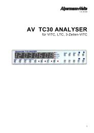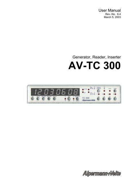
Generator, Reader, Inserter AV-TC 300 - Alpermann + Velte
Generator, Reader, Inserter AV-TC 300 - Alpermann + Velte
Generator, Reader, Inserter AV-TC 300 - Alpermann + Velte
- No tags were found...

Create successful ePaper yourself
Turn your PDF publications into a flip-book with our unique Google optimized e-Paper software.
User Manual<br />
Rev.-No. 6.4<br />
March 5, 2003<br />
<strong>Generator</strong>, <strong>Reader</strong>, <strong>Inserter</strong><br />
<strong>AV</strong>-<strong>TC</strong> <strong>300</strong>
User Manual <strong>AV</strong>-<strong>TC</strong> <strong>300</strong><br />
A1 Copyright<br />
Copyright © by <strong>Alpermann</strong>+<strong>Velte</strong> Electronic Engineering GmbH 1997-99. All<br />
rights reserved.<br />
Information in this publication supersedes that in all previously published material.<br />
Specifications and price change privileges reserved.<br />
For further information, contact your local dealer or<br />
<strong>Alpermann</strong> + <strong>Velte</strong><br />
Electronic Engineering GmbH<br />
D-42369 Wuppertal, Otto-Hahn-Str. 42<br />
Tel.: ++49 - (0)202 - 2441110<br />
Fax: ++49 - (0)202 - 2441115
User Manual <strong>AV</strong>-<strong>TC</strong> <strong>300</strong><br />
A2 CE - Declaration of Conformity<br />
We,<br />
<strong>Alpermann</strong> + <strong>Velte</strong><br />
Electronic Engineering GmbH<br />
D-42369 Wuppertal, Otto-Hahn-Str. 42<br />
declare under our sole responsibility that the<br />
<strong>Generator</strong>, <strong>Reader</strong>, <strong>Inserter</strong> <strong>AV</strong>-<strong>TC</strong> <strong>300</strong><br />
to which this declaration relates is in conformity with the following standards:<br />
1. EN 55022, Class B<br />
2. IEC 801-2<br />
3. IEC 801-3/ENV 50140<br />
4. EN 61000-41<br />
The following necessary conditions are to fulfil:<br />
The ground connectors must be connected to ground.<br />
The audio, video and data cables must be shielded.
User Manual <strong>AV</strong>-<strong>TC</strong> <strong>300</strong><br />
A3 General hints for safe operation<br />
General hints:<br />
Damage due to transportation:<br />
Location:<br />
Mains connection:<br />
Care:<br />
Repairs:<br />
Please only use the equipment in dry<br />
rooms and according to the directions.<br />
Handle the <strong>AV</strong>-<strong>TC</strong> <strong>300</strong> with the same care<br />
as any other studio equipment. Pay attention<br />
to the corresponding instructions in<br />
the operation manual of our equipment.<br />
In case of obvious damage caused during<br />
transportation, please inform the responsible<br />
forwarding agency. Please also get<br />
directly in touch with your dealer.<br />
Ensure that the equipment is installed so<br />
that sufficient air circulation is provided.<br />
Do not expose the equipment to extreme<br />
temperatures, dust, humidity, vibrations<br />
and strong electromagnetic fields.<br />
Before connecting the AC connector with<br />
the mains outlet, insert any other cables<br />
and firstly check the mains voltage.<br />
At first disconnect the AC connector!<br />
Please use a soft cloth to clean the cabinet<br />
case. Do not use any cleaning<br />
agents.<br />
As electronic state-of-the-art components<br />
have been used in your equipment, no<br />
maintenance is required. The unit does<br />
not contain any parts which might be repaired<br />
by yourself. For this reason, any<br />
intervention should only be performed by<br />
an authorised service partner.
User Manual <strong>AV</strong>-<strong>TC</strong> <strong>300</strong><br />
A4 Welcome to the <strong>AV</strong>-<strong>TC</strong> <strong>300</strong>!<br />
Your Time Code Toolbox <strong>AV</strong>-<strong>TC</strong> <strong>300</strong> is a comprehensive state-of the-art product,<br />
which covers - according to its configuration - nearly all Time Code applications<br />
ever occurring in a studio. The newly designed operation structure using single<br />
dedicated buttons for everyday settings, and a setup menu for the rather basically<br />
adjustments makes the <strong>AV</strong>-<strong>TC</strong> <strong>300</strong> an easy-to-handle unit. Still we advise to keep<br />
the menu overview close to the unit. It may be a tool in itself suggesting solutions<br />
to very special tasks. Also make use of the note sheet (Appendix) to write down<br />
your basic settings, especially if the <strong>AV</strong>-<strong>TC</strong> <strong>300</strong> is operated by different people<br />
from time to time. (See M4.7 PROFILE)<br />
Should you wish to have a close look at the basic principles of SMPTE/EBU Time<br />
Codes, ask your dealer for our information brochure "Introduction to the Basic<br />
Principles of SMPTE/EBU Time Code“.<br />
Best Regards<br />
<strong>Alpermann</strong> + <strong>Velte</strong><br />
Electronic Engineering GmbH<br />
Contents of this operating instructions:<br />
The chapter entitled "Operation of the equipment" contains a description of the<br />
function groups which are numbered in accordance with the corresponding menus.<br />
The numbers which are identical with the individual menu items are identified by<br />
"M" (e.g. M3.6 Insertion (Size)). Any indications appearing in the display of the<br />
equipment are shown in ITALIC, whereas all operating buttons appear in bold<br />
letters.
User Manual <strong>AV</strong>-<strong>TC</strong> <strong>300</strong><br />
TABLE OF CONTENTS<br />
Page<br />
A1 COPYRIGHT<br />
A2 DECLARATION OF CONFORMITY<br />
A3 GENERAL HINTS FOR SAFE OPERATION<br />
A4 WELCOME TO THE <strong>AV</strong>-<strong>TC</strong> <strong>300</strong><br />
B1 FRONT PANEL AND DISPLAY 1<br />
B2 MENU STRUCTURE 4<br />
B3 CONNECTIONS 5<br />
TECHNICAL SPECIFICATIONS 5<br />
*1 „SDC out“ vs. „SDC invert. out“ 6<br />
*2 Parallel Interface 6<br />
*3 Assignment of RS232 / 422 / 485 8<br />
B4 OPERATION 9<br />
0.1 Starting 10<br />
0.2 Menu Structure 11<br />
0.3 Menu Handling 11<br />
0.4 Fast Recall of Profiles 12<br />
0.5 Reset 12<br />
1. GENERATOR 13<br />
1.1 Display Selection 13<br />
1.2 Programming of <strong>Generator</strong> Time 13<br />
1.3 Adjustment of User Bits 13<br />
M1.0 GENERATOR MENU 14<br />
M1.1 Framerate 14<br />
M1.2 DVI<strong>TC</strong> 14<br />
M1.3 Jam Sync 15<br />
2. READER 19<br />
2.1 Display Selection 19<br />
2.2 Indication of the active <strong>Reader</strong> 19<br />
M2.0 READER MENU 20<br />
M2.1 Source 20<br />
M2.2 Event Mode 20<br />
M2.3 Event 20<br />
M2.4 Analysis 20<br />
M2.5 Framerate 21<br />
M2.6 DVI<strong>TC</strong> 21<br />
3. VIDEO INSERTION 24<br />
3.1 Positioning of the Insertion 24<br />
M3.0 INSERTION MENU 24<br />
M3.1 Source 24<br />
M3.2 Text 27
User Manual <strong>AV</strong>-<strong>TC</strong> <strong>300</strong><br />
M3.2 Size 28<br />
M3.4 Border 28<br />
M3.5 Character 29<br />
M3.6 Mask 30<br />
M3.7 Show 30<br />
4. SYSTEM SETUP 31<br />
M4.0 SYSTEM SETUP MENU 31<br />
M4.1 Configuration 31<br />
M4.2 Channel 32<br />
M4.3 Width 32<br />
M4.4 Norm 33<br />
M4.5 Interface 33<br />
M4.6 Reference 34<br />
M4.7 Profile 36<br />
C1 FACTORY DEFAULTS OF <strong>AV</strong>-<strong>TC</strong> <strong>300</strong> 37<br />
C2 CHARACTER SET OF <strong>AV</strong>-<strong>TC</strong> <strong>300</strong> 38<br />
C3 COMMUNICATION PROTOCOL 39<br />
Table of Interface Commands 40
User Manual <strong>AV</strong>-<strong>TC</strong> <strong>300</strong><br />
Page 1<br />
B1 Front Panel and Display<br />
Functions of Front Panel and Display<br />
1 Numerical Display Shows either the time- or user-data of the generator or<br />
of the reader. Selection is done using the keys time / user<br />
and generator / reader .<br />
2 set Starts the selection mode for the time and user values<br />
of the generator.<br />
3 hours Selects the values of hours during the selection mode.<br />
Out of the selection mode this button is used for recalling<br />
the user defined profile, which is stored in PROFILE<br />
1 (see M4.7).<br />
4 minutes Selects the values of minutes during the selection<br />
mode.<br />
Out of the selection mode this button is used for recalling<br />
the user defined profile, which is stored in PROFILE<br />
2 (see M4.7).<br />
5 hours Selects the values of seconds during the selection<br />
mode.<br />
Out of the selection mode this button is used for recalling<br />
the user defined profile, which is stored in PROFILE<br />
3 (see M4.7).
User Manual <strong>AV</strong>-<strong>TC</strong> <strong>300</strong><br />
Page 2<br />
6 frames Selects the values of frames during the selection mode.<br />
Out of the selection mode this button is used for recalling<br />
the user defined profile, which is stored in PROFILE<br />
4 (see M4.7).<br />
7 time / user Switches alternatively time or user values to the<br />
numerical display.<br />
Time values<br />
The diode is lit up.<br />
User values<br />
The diode is off.<br />
8 generator / reader Switches alternatively generator or reader values to the<br />
numerical display.<br />
<strong>Generator</strong> values<br />
The diode is lit up.<br />
<strong>Reader</strong> values<br />
The diode is off.<br />
9 jam The diode indicates the activity of the jam function.<br />
The reader value is transmitted to the generator once.<br />
SINGLE<br />
Single regeneration of all read<br />
values.<br />
The diode flashes.<br />
CONTINUOUS Continuous regeneration of all<br />
read values.<br />
The diode is lit up.<br />
No transmission The diode is off.<br />
10 ltc / dvitc The diode indicates the Time Code, which is read.<br />
L<strong>TC</strong><br />
The diode is lit up.<br />
DVI<strong>TC</strong><br />
The diode is off.<br />
No Time Code<br />
The diode flashes.<br />
11 Cursor keys, which are used for<br />
- positioning of the video insertion.<br />
- programming of the time values in selection mode.<br />
- selection of submenus.<br />
- adjustment of parameters.<br />
- positioning of text insertion.<br />
12 carrier The diode indicates if a video signal is applied.<br />
13 pal / ntsc The diode indicates the standard of the video signal.<br />
PAL (625/25)<br />
The diode is lit up.<br />
NTSC (525/30)<br />
The diode is off.
User Manual <strong>AV</strong>-<strong>TC</strong> <strong>300</strong><br />
Page 3<br />
14 menue / position Enables and disables either the menu section or the<br />
positioning of video insertion.<br />
Selection of menu<br />
The diode is lit up.<br />
Positioning of video insertion The diode is off.<br />
15 error The diode will shine, if a general error message is<br />
given.<br />
16 enter Execution and confirmation of menu functions and<br />
settings.<br />
Execution of SINGLE jam.<br />
17 diodes These diodes indicate the actual profile.<br />
Switching off/on the LED display:<br />
2 set then<br />
14 menue Switches off the display, with only a decimal point at the<br />
right side that is lit up .<br />
7 time / user or<br />
8 generator / reader Switches on the display.
User Manual <strong>AV</strong>-<strong>TC</strong> <strong>300</strong><br />
Page 4<br />
B2 Menu Structure
User Manual <strong>AV</strong>-<strong>TC</strong> <strong>300</strong><br />
Page 5<br />
B3 Connections<br />
GROUND<br />
9-PIN D-SUB<br />
RS 232/422/485<br />
optional<br />
25-PIN D-SUB<br />
PARALLEL<br />
optional<br />
POWER<br />
ON/OFF<br />
L<strong>TC</strong> IN L<strong>TC</strong> OUT POWER SDC<br />
OUT<br />
SDC<br />
OUT<br />
SDC<br />
LOOP OUT<br />
SDC<br />
IN<br />
Technical Specifications<br />
Dimensions<br />
Weight<br />
Operating voltage<br />
Acceptable ambient temperature<br />
Housing ½ 19“, Depth 277mm;<br />
Option: 19“- slide-in module for one or two <strong>TC</strong> <strong>300</strong><br />
about 1.8 kg<br />
10-30V=, ca. 6VA / external power supply unit<br />
0°- 40° C<br />
Relative humidity 35 - 85 %<br />
Inputs: Connector Signal description<br />
Power 4pol XLR M pin signal<br />
1 GND<br />
4 Vcc<br />
10-30V=<br />
GND 4mm socket Ground<br />
L<strong>TC</strong> XLR 3 F pin signal<br />
1 GND<br />
2/3 L<strong>TC</strong> in<br />
balanced and floating / 100mV-5Vpp /<br />
20 kOhm<br />
Digital video BNC SDC / 800 mVss / 75 Ohm<br />
Outputs:<br />
L<strong>TC</strong> XLR 3 M pin signal<br />
1 GND<br />
2/3 L<strong>TC</strong> out<br />
balanced / 1Vpp / < 50 Ohm<br />
Digital video *1 BNC SDC / 800 mVss / 75 Ohm<br />
2х OUT and 1х Loop OUT<br />
Interfaces<br />
Parallel *2<br />
25-pol D-Sub socket<br />
RS-232 or RS 422/ RS 485 *3 9-pol D-Sub modified SONY protocol
User Manual <strong>AV</strong>-<strong>TC</strong> <strong>300</strong><br />
Page 6<br />
*1 „SDC out“ vs. „SDC invert. out“<br />
The SDC-outputs deliver to each other an output signal, which is inverted in<br />
polarity. The information of both outputs is identical. According to EBU-norm<br />
(EBU interface for 625-line digital video signals at the 4:2:2 level of CCIR Recommendation<br />
601, Chapter 3, 1.2. Channel Coding, Second Edition, January 1992)<br />
the code is equivalent to „scrambled NRZI“. This code guarantees synchronising<br />
to the signal and reading the data independently from polarity.<br />
*2 Parallel Interface<br />
Assignment of 25pin D-Sub F<br />
Pin<br />
Signal<br />
1 n.c.<br />
14 n.c.<br />
2 I/O 1<br />
15 n.c.<br />
3 I/O 2<br />
16 n.c.<br />
4 I/O 3<br />
17 +5V, 200mA<br />
5 I/O 4<br />
18 GND<br />
6 I/O 5<br />
19 GND<br />
7 I/O 6<br />
20 GND<br />
8 I/O 7<br />
21 GND<br />
9 I/O 8<br />
22 GND<br />
10 n.c.<br />
23 GND<br />
11 n.c.<br />
24 GND<br />
12 n.c.<br />
25 GND<br />
13 n.c.<br />
The parallel interface of <strong>AV</strong>-<strong>TC</strong> <strong>300</strong> makes eight universal in-/ outputs with opencollector<br />
drivers, available to the user. Up to eight external keys may be connected.<br />
Every key may correspond to a diode. For powering of the LED’s a<br />
voltage of +5V is available which can be loaded up to max. 200mA. The load of<br />
the drivers may range up to 30 mA.<br />
The functions Insert, Time, User and Mask may be programmed as switches in<br />
menue 4.5.6.
User Manual <strong>AV</strong>-<strong>TC</strong> <strong>300</strong><br />
Page 7<br />
Connection of 8 keys<br />
Connection of diodes<br />
Pin<br />
Action<br />
+5V<br />
2<br />
18<br />
Load Profile 1<br />
220Ω<br />
(150Ω<br />
- 330 Ω)<br />
3<br />
19<br />
Load Profile 2<br />
A<br />
K<br />
LED<br />
4<br />
20<br />
Load Profile 3<br />
I/O<br />
Key<br />
5<br />
21<br />
Load Profile 4<br />
GND<br />
6<br />
22<br />
Insert on/off<br />
7<br />
23<br />
Time on/off<br />
8<br />
24<br />
User on/off<br />
9<br />
25<br />
Mask on/off
User Manual <strong>AV</strong>-<strong>TC</strong> <strong>300</strong><br />
Page 8<br />
*3 Assignment of RS232 / 422 / 485<br />
Pin RS232 RS422 RS485<br />
1 n.c. n.c. n.c.<br />
6 n.c. TxC n.c.<br />
2 TxD TxA RxTxA<br />
7 CTS TxB RxTxB<br />
3 RxD RxB n.c.<br />
8 RTS RxA n.c.<br />
4 n.c. RxC Term<br />
9 n.c. n.c. n.c.<br />
5 GND GND GND<br />
Remarks:<br />
n.c. = not connected<br />
RxC; TxC = GND via 100 Ω<br />
Term = +5V via 330 Ω<br />
Serial Interface RS485<br />
The serial interface RS485 of <strong>AV</strong>-<strong>TC</strong> <strong>300</strong> may control up to 250 devices via a<br />
common interface, e.g. a computer. For that every <strong>AV</strong>-<strong>TC</strong> <strong>300</strong> gets a device<br />
address (ID) which range between 1 and 250 (see M4.5.5). Commands, which<br />
are sent via bus, contain the ID and address a special device. This device<br />
evaluates the command and sends a return via bus (see protocol SONY+ID,<br />
M4.5.2).<br />
Connections<br />
RS485 is connected as a bus. Beginning and end must be properly terminated<br />
right. One end is terminated on the PC-card the other on the cable. The operating<br />
voltage is given by <strong>AV</strong>-<strong>TC</strong> <strong>300</strong> via 330 Ohm on pin 4. The following pin numbers<br />
of the PC-card relate to RS485-card #13601 of W&T.<br />
PC <strong>TC</strong><strong>300</strong> <strong>TC</strong><strong>300</strong> <strong>TC</strong><strong>300</strong> <strong>TC</strong><strong>300</strong><br />
DSUB9-F DSUB9-M DSUB9-M DSUB9-M DSUB9-M<br />
Signal Pin Pin Pin Pin Pin<br />
In A 2 --o-------- 2 ----- 2 ----- 2 -- ¨¨¨ -- 2 -------------+<br />
| |<br />
Out A 1 --+ |<br />
____ |<br />
In B 7 --o-------- 7 ----- 7 ----- 7 -- ¨¨¨ -- 7 --o--|____|--o<br />
| | 120R |<br />
Out B 6 --+ 4 --+ |<br />
____ |<br />
Gnd 5 ----------- 5 ----- 5 ----- 5 -- ¨¨¨ -- 5 -----|____|--+<br />
330R<br />
This results in following termination network:<br />
+5V – 330R – B – 120R – A – 330R – GND
User Manual <strong>AV</strong>-<strong>TC</strong> <strong>300</strong><br />
Page 9<br />
B4 OPERATION<br />
With their <strong>AV</strong>-<strong>TC</strong> <strong>300</strong>, <strong>Alpermann</strong>+<strong>Velte</strong>, the Time Code specialists located in<br />
Wuppertal, present a modular concept permitting user-specific configurations.<br />
The basic unit includes one digital video channel and the control panel with LED<br />
display and function keys. Modules permitting to define specific applications are<br />
optionally available. The following modules may be built in:<br />
• L<strong>TC</strong> High Speed <strong>Reader</strong><br />
• L<strong>TC</strong> Play Speed <strong>Reader</strong><br />
• L<strong>TC</strong> <strong>Generator</strong><br />
• DVI<strong>TC</strong> <strong>Reader</strong><br />
• DVI<strong>TC</strong> <strong>Generator</strong><br />
• Serial Interface RS 232<br />
• Serial Interface RS 422<br />
• Serial Interface RS 485<br />
• Parallel Interface<br />
• Insertion for times of the studio timer system <strong>AV</strong>-MTD (Software).<br />
The menu item CONFIGURATION (M4.1) in the SETUP menu and the display<br />
message after power-on contain information on the modules integrated into your<br />
<strong>AV</strong>-<strong>TC</strong> <strong>300</strong> unit. Correspondingly, only those sections of the operating instructions<br />
are relevant which refer to the corresponding configuration.
User Manual <strong>AV</strong>-<strong>TC</strong> <strong>300</strong><br />
Page 10<br />
0.1 Starting<br />
<strong>AV</strong>-<strong>TC</strong> <strong>300</strong> is powered on by using the flip switch on the rear. Directly after<br />
turning on the modules, which are actually installed, are shown on the display.<br />
The following information is given:<br />
M = MTD Software<br />
Dark = no MTD Software<br />
Special design<br />
Dark = no Special Design<br />
DVI<strong>TC</strong><br />
0=noDVI<strong>TC</strong><br />
1 = <strong>Reader</strong><br />
4 = <strong>Generator</strong><br />
5 = <strong>Reader</strong> + <strong>Generator</strong><br />
L<strong>TC</strong><br />
0=noL<strong>TC</strong><br />
1 = Play Speed <strong>Reader</strong><br />
2 = High Speed <strong>Reader</strong><br />
4 = <strong>Generator</strong><br />
5 = <strong>Generator</strong> + Play Speed <strong>Reader</strong><br />
6 = <strong>Generator</strong> + High Speed <strong>Reader</strong><br />
Version <strong>Inserter</strong> Chip<br />
Version <strong>Reader</strong> Chip<br />
Firmware Version 12 = 1.2<br />
The <strong>AV</strong>-<strong>TC</strong> <strong>300</strong> which is shown in the example above has got the following<br />
configuration:<br />
Firmware version: 1.2<br />
Version of the readers: 1<br />
Version of the inserter: 2<br />
L<strong>TC</strong> generator<br />
DVI<strong>TC</strong> reader and DVI<strong>TC</strong> generator<br />
No special design<br />
No MTD software
User Manual <strong>AV</strong>-<strong>TC</strong> <strong>300</strong><br />
Page 11<br />
0.2 Menu Structure<br />
The setup menu is enabled by the key menu / position . The actual menu selection is<br />
indicated by the diode. The menu setup is inserted in the monitor. The menu is<br />
left by pressing menu / position again. The last previously active menu selection<br />
remains active and is recalled as soon as the menu is switched on again.<br />
The menu contains four main menus:<br />
1 GENERATOR Adjustment of the generator<br />
2 READER Adjustment of the reader<br />
3 INSERTION Adjustment of the insertion<br />
4 SETUP Adjustment of system parameters<br />
0.3 Menu Handling<br />
You move between the main menus (1 st menu level, 1.0, 2.0, 3.0 or 4.0) using the<br />
keys and . Changing between the main menu items is only possible at this<br />
level. This possibility is indicated in the command level by the signs and .<br />
The 2 nd menu level is recalled by pressing the key (sign in command level).<br />
Within the 2 nd menu level you move between the items using the keys and .<br />
The keys and serve to select the function to be adjusted. The actual adjustment<br />
is indicated by . For safety reasons the new adjustments have to be<br />
confirmed by pressing the enter key.<br />
Some items dispose of submenus (3 rd menu level). For polling this level use the<br />
key enter. The selection of items and adjustments is done as in the 2 nd level.<br />
To leave the menu levels two different operations are possible:<br />
<br />
Moves between the levels in ascendant order until the<br />
wished level is reached.<br />
menu / position<br />
Finishes the whole menu. The last previously active<br />
item remains active and is recalled as soon as the<br />
menu is switched on again.
User Manual <strong>AV</strong>-<strong>TC</strong> <strong>300</strong><br />
Page 12<br />
0.4 Fast Recall of Profiles<br />
Using the buttons hours, minutes, seconds, frames out of the selection mode,<br />
the profiles, which have been store before (see M4.7 PROFILE) may be recalled<br />
and changed quickly.<br />
For that please ensure that the selection mode is not used. The following profiles<br />
are available:<br />
hours<br />
Out of the selection mode PROFILE 1 is recalled by<br />
using this button. The diode f1 is lit up.<br />
minutes<br />
Out of the selection mode PROFILE 2 is recalled by<br />
using this button. The diode f2 is lit up.<br />
seconds<br />
Out of the selection mode PROFILE 3 is recalled by<br />
using this button. The diode f3 is lit up.<br />
frames<br />
Out of the selection mode PROFILE 4 is recalled by<br />
using this button. The diode f4 is lit up.<br />
0.5 Reset<br />
For reset of all adjustments to factory default you have got two different possibilities:<br />
menu / position + enter + power up<br />
The default adjustments are loaded. The user defined<br />
adjustments survive.<br />
set + + power up<br />
The default adjustments are loaded. The user defined<br />
adjustments are deleted.
User Manual <strong>AV</strong>-<strong>TC</strong> <strong>300</strong><br />
Page 13<br />
1. GENERATOR<br />
Apart from the menu adjustments the following keys are available for the generator<br />
configuration:<br />
hours minutes seconds frames<br />
set<br />
enter<br />
generator / reader<br />
1.1 Display Selection<br />
time / user<br />
With the generator / reader key the generated data can be switched over to the 8-digit<br />
display. When the generator values are indicated, the diode on the left hand of the<br />
generator / reader button lights up.<br />
The time / user button serves to switch over between time and user values. When the<br />
time values are displayed, the adjacent diode lights up; when user values are<br />
displayed, the diode remains switched off.<br />
1.2 Programming of <strong>Generator</strong> Time<br />
Switch the numerical display to indication of generator values using the generator<br />
/ reader key. The adjacent diode is lit up. Now select the option time using the<br />
key time / user . The adjacent diode is lit up. The display indicates the actual generator<br />
time in hours : minutes : seconds : frames.<br />
The programming mode is activated by the key set. The numerical display shows<br />
the last set time. Using the key hours the hours, using the key minutes the<br />
minutes, using the key the seconds and using the key frames the frames are<br />
selected. The selected digits flash. Use the keys and to change the values.<br />
Only plausible time values and frame numbers are accepted. Confirm by pressing<br />
enter.<br />
Until this moment you can cancel the operation pressing set again: the set mode<br />
is left without any change of time values.<br />
1.3 Adjustment of User Bits<br />
Switch the numerical display to indication of generator values using the generator<br />
/ reader key. The diode is lit up. Now select the option time using the key time / user .<br />
The diode doesn’t shine. The programming mode is activated by the key set. The<br />
numerical display shows the last set value. Using the keys hours, minutes,<br />
seconds and frames one of the four user groups are activated. The selected<br />
digits flash. Use the keys and to change the values. All hexadecimal values<br />
(0 to 9 and A to F) are available. Confirm by pressing enter.<br />
Until this moment you can cancel the operation pressing set again: the set mode<br />
is left without any change of user values.
User Manual <strong>AV</strong>-<strong>TC</strong> <strong>300</strong><br />
Page 14<br />
M1.0 <strong>Generator</strong> Menu<br />
M1.1 Framerate<br />
The <strong>AV</strong>-<strong>TC</strong> <strong>300</strong> generates the framerates 24, 25, 30 and 30Dropframe. The<br />
actual choice is indicated by . A different framerate is selected using the cursor<br />
keys and . Press enter to confirm the selection. The menu display shows <br />
as receipt.<br />
As the <strong>AV</strong>-<strong>TC</strong> <strong>300</strong> automatically detects the used video standard and the resulting<br />
frame rates (25 frames for 625/25 frames and 30 DF for 525/30), the AUTO option<br />
is selected by factory. This AUTO setting is generally recommended.<br />
M1.2 DVI<strong>TC</strong><br />
The permitted range for the insertion of VI<strong>TC</strong> data is limited to video lines 6 to 22<br />
in 625/25 (PAL/Secam) and to lines 10 to 20 in 525/30 (NTSC). These limits are<br />
set automatically according to the video norm.<br />
<strong>AV</strong>-<strong>TC</strong> <strong>300</strong> generates DVI<strong>TC</strong> either in two single lines (2-LINES) or in a coherent<br />
block of maximal 16 lines (BLOCK).<br />
To modify the adjustments press enter to enable the 3 rd menu level. The actual<br />
choice of items can be checked using the keys and . Mode selections are:<br />
M1.2.1 MODE<br />
Adjustment of mode.<br />
The current setting is marked with a . If this value<br />
has to be modified, the desired setting is selected with<br />
the keys and . Confirm the selection with enter.<br />
Select from:<br />
2-LINES<br />
BLOCK<br />
OFF<br />
M1.2.2 FIRST LINE Adjustment of first line. The lines 6 to 22 (625/25) resp.<br />
10 to 20 (525/30) are available.<br />
The current setting is marked with a . If this value<br />
has to be modified, the desired setting is selected with<br />
the keys and . Confirm the selection with enter.
User Manual <strong>AV</strong>-<strong>TC</strong> <strong>300</strong><br />
Page 15<br />
M1.2.3 LAST LINE<br />
Adjustment of last line. The lines 6 to 22 (625/25) resp.<br />
10 to 20 (525/30) are available.<br />
The current setting is marked with a . If this value<br />
has to be modified, the desired setting is selected with<br />
the keys and . Confirm the selection with enter.<br />
Caution:<br />
We recommend that the two lines should not be adjacent. The last<br />
line should be at least two lines larger than the first. If only one line<br />
is adjusted, both values must be identical. According to the suggestions<br />
of the standard, both lines are set to "14" at the factory.<br />
M1.3 Jam Sync<br />
The adjustments of the programmable jam function are carried out in the submenu<br />
of this menu item, which is recalled with the enter key. The items of the submenu<br />
are selected with the and keys. The following items are available:<br />
M1.3.1 MODE<br />
Adjustment of mode.<br />
The current setting is marked with a . If this value<br />
has to be modified, the desired setting is selected with<br />
the keys and . Confirm the selection with enter.<br />
Select from:<br />
SINGLE<br />
The next read out time and/or<br />
user value is taken over once.<br />
The jam diode flashes. This<br />
mode is activated, if the enter<br />
key is again pressed after completion<br />
of the menu. Only then<br />
the next readout value is taken<br />
over.<br />
CONTINUOUS Every read time and/or user<br />
value is taken over, and values<br />
are continuously counted during<br />
gaps. The jam diode is lit<br />
up.<br />
CONT 0 FRAMES<br />
CONT 8 FRAMES<br />
CONT 16 FRAMES<br />
As with CONTINUOUS, the readout<br />
Time Code values are continuously<br />
taken over. If no<br />
value can be read, the generator<br />
will stop after having<br />
counted on for 0, 8 or 16<br />
frames, i.e. a „still“ Time Code
User Manual <strong>AV</strong>-<strong>TC</strong> <strong>300</strong><br />
Page 16<br />
M1.3.2 VALUES<br />
M1.3.3 JAM-OFFSET<br />
will be generated („flywheel<br />
function“).<br />
CONVERTER<br />
As with CONT 0 FRAMES, the<br />
read-out Time Code values are<br />
continuously taken over. This<br />
is done every time, not only if<br />
the Time Code that was read is<br />
counting up in play speed.<br />
With this setting it is possible to<br />
convert one Time Code to another.<br />
CVRT W/ TOLERANCE Similar to CONVERTER, but the<br />
read-out values are only taken<br />
over, if the difference to the actual<br />
generator values is greater<br />
than 3 frames. The chapter<br />
“Time Code Regeneration” below<br />
describes the details.<br />
CONT W/ TOLERANCE Similar to CONTINOUS, but the<br />
read-out values are only taken<br />
over, if the difference to the actual<br />
generator values is greater<br />
than 3 frames. The chapter<br />
“Time Code Regeneration” below<br />
describes the details.<br />
OFF<br />
Any time and user values are<br />
not taken over. The jam diode<br />
is off.<br />
Specification of the values.<br />
The current setting is marked with a . If this value<br />
has to be modified, the desired setting is selected with<br />
the keys and . Confirm the selection with enter.<br />
Select from:<br />
TIME<br />
Single synchronization to<br />
source time.<br />
USER<br />
Single synchronization to<br />
source user.<br />
TIME+USER<br />
Continuous synchronization of<br />
time and user.<br />
TIME TO USER Synchronization to source time<br />
into user.<br />
Every jam function can shift the period of time gains by<br />
the reader by adding a preset time value.
User Manual <strong>AV</strong>-<strong>TC</strong> <strong>300</strong><br />
Page 17<br />
Indication of the amount to be added to the reader time.<br />
After selection of this menu item, an 8-digit time display<br />
(HOURS : MINUTES : SECONDS : FRAMES) appears in the inserted<br />
adjustment menu. Use the hours, minutes,<br />
seconds and frames buttons to select the corresponding<br />
block of values. The selected figures will flash. The<br />
and keys are used to enter the values of the desired<br />
offset time. Confirm the entry with enter. A minus<br />
offset of e.g. one second is achieved by entering<br />
23:59:59:00.<br />
Application: Time Code Regeneration, “Converter with Tolerance”<br />
The problem of normal Jam-Sync<br />
As a standard proceeding, a read Time Code is checked regarding time plausibility<br />
and up-counting sequence before it will be transferred to the Time Code generator.<br />
Such a check will not prevent frame jumps occurring in case of e.g. lack of<br />
synchronization between reader and generator. This special Jam-Sync mode<br />
improves the Time Code regeneration - at least if the recording time is limited.<br />
Functional description<br />
Only if the difference between the read Time Code and the actual generated value<br />
exceeds a threshold value (in this case = 3 frames), the read value will be transferred<br />
to the generator. Otherwise the generator will continue counting freely. This<br />
way the generator outputs a continuous Time Code without any frame jumps.<br />
A frame accurate lock after a start will be achieved by accepting all read values for<br />
a period of two seconds after the threshold has been exceeded. This overcomes a<br />
lost of synchronization during, for example “the run-up time of a VCR”.<br />
The generator remains in the „free-running mode“ if no more values will be read<br />
(infinite „flywheel“).<br />
With this proceeding please note:<br />
If the last reader value (2 seconds after exceeding the threshold) has been<br />
transferred while the reader Time Code is not yet phase-locked to the generator<br />
Time Code (e.g. if a run-up phase is delayed), it is possible that values will be<br />
generated continuously which constantly differ to the reader Time Code, difference<br />
up to 3 frames.<br />
In case the reader Time Code is not synchronized to the generator, a difference is<br />
being build up which will exceed the threshold. Then a correction will be made, i.e.<br />
instead of frequently generating one-frame jumps now - less frequently - 4-frames<br />
jumps occur. The shorter the time of processing (recording) the less will be the<br />
probability of frame jumps.<br />
Operating<br />
M1.3.1<br />
(<strong>Generator</strong> / Jam Sync / Mode) CVRT W/ TOLERANCE.
User Manual <strong>AV</strong>-<strong>TC</strong> <strong>300</strong><br />
Page 18<br />
Application: Standard Conversion<br />
One application of Jam Sync is the conversion of Time Code between two standards,<br />
e.g. 25 Hz L<strong>TC</strong> to 525/30 D-VI<strong>TC</strong>. <strong>AV</strong>-<strong>TC</strong> <strong>300</strong> detects this by seeing the<br />
different frame rates of reader and generator, and modifies the way of take-over<br />
the values in the jam functions. The converter modes CONVERTER and<br />
CVRT W/ TOLERANCE remain the same, but all other jam modes do the take-over<br />
of the values only once a second, in the last frame respectively.<br />
Particularly suitable for standard conversion is the jam mode<br />
CONT W/ TOLERANCE. As an example, a standard conversion from 625/25 D-<br />
VI<strong>TC</strong> to 525/25 D-VI<strong>TC</strong> will be shown, using two <strong>AV</strong>-<strong>TC</strong> <strong>300</strong>. The first unit has a<br />
D-VI<strong>TC</strong> reader and a L<strong>TC</strong> generator, and converts D-VI<strong>TC</strong> to L<strong>TC</strong>. The second<br />
unit has a L<strong>TC</strong> reader and a D-VI<strong>TC</strong> generator, and converts L<strong>TC</strong> to D-VI<strong>TC</strong>.<br />
The video input of the first unit has to be fed with the 625/25 video signal. The<br />
units reads the D-VI<strong>TC</strong> and converts it to a L<strong>TC</strong> with 25 Hz. Based on the factory<br />
setting (M4.7), the following setting has to be made:<br />
M1.3.1 GENERATOR / JAM SYNC / MODE CONVERTER<br />
Additionally, if required, in M1.3.3 an offset may be added. This offset is handled<br />
as a 625/25 Time Code.<br />
The video signal can be taken from the video loop output, processed by the video<br />
system converter, where it is converted to a 525/30 video signal. Then in the<br />
second <strong>AV</strong>-<strong>TC</strong> <strong>300</strong> the conversion of the 25 Hz L<strong>TC</strong> to a 525/30 D-VI<strong>TC</strong> will be<br />
made. Thus, the L<strong>TC</strong> will be connected to the L<strong>TC</strong> input of the unit, and the video<br />
signal taken from the video system converter to the video input. Based on the<br />
factory setting (M4.7), the following setting has to be made:<br />
M1.3.1 GENERATOR / JAM SYNC / MODE CONT W/ TOLERANCE<br />
M3.7 INSERTION / SHOW OFF<br />
If required, in M1.3.3 an additional offset may be set (installed). This offset is<br />
handled as a 525/30 Time Code. Now at the video output of the second unit, the<br />
converted video signal can be taken, including a time-equal D-VI<strong>TC</strong> relative to the<br />
source video.
User Manual <strong>AV</strong>-<strong>TC</strong> <strong>300</strong><br />
Page 19<br />
2. READER<br />
Apart from the menu adjustment the following keys are available for the reader<br />
configuration:<br />
generator / reader<br />
time / user<br />
2.1 Display Selection<br />
With the generator / reader key the read data can be switched over to the 8-digit display.<br />
When the reader values are indicated, the diode on the left hand of the generator<br />
/ reader button is off.<br />
The time / user button serves to switch over between time and user values. When the<br />
time values are displayed, the adjacent diode lights up; when user values are<br />
displayed, the diode remains switched off.<br />
2.2 Indication of the active <strong>Reader</strong><br />
The <strong>AV</strong>-<strong>TC</strong> <strong>300</strong> detects automatically which time-code is read out. The ltc / dvitc<br />
diode indicates the current time-code. If L<strong>TC</strong> is read, the diode is lit; if DVI<strong>TC</strong> is<br />
read, it is off.
User Manual <strong>AV</strong>-<strong>TC</strong> <strong>300</strong><br />
Page 20<br />
M2.0 <strong>Reader</strong> Menu<br />
M2.1 Source<br />
The item source serves to select the active reader. Use the keys and to<br />
recall the desired reader. Confirm your selection with enter. Select from:<br />
L<strong>TC</strong><br />
DVI<strong>TC</strong><br />
AUTO<br />
M2.2 Event Mode<br />
The <strong>AV</strong>-<strong>TC</strong> <strong>300</strong> features events, which are triggered by read Time Code values.<br />
These times can be adjusted individually.<br />
The current setting is marked with a . If this value has to be modified, the<br />
desired setting is selected with the keys and . Confirm the selection with<br />
enter. Select from:<br />
GPI SET<br />
Sets GPI output.<br />
GPI OFF<br />
Resets GPI output.<br />
GPI PULSE POS Sets GPI pulse positive.<br />
GPI PULSE NEG Sets GPI pulse negative.<br />
OFF<br />
No event.<br />
M2.3 Event<br />
In this mode, the time is programmed for the event which was selected in the<br />
event mode. After having selected this menu item, an 8-digit time display (HOURS :<br />
MINUTES : SECONDS : FRAMES) is inserted in the adjustment menu. Use only the hours,<br />
minutes, seconds and frames buttons to select the corresponding numeric block.<br />
The selected numeric block flashes. The and keys serve to enter the values<br />
of the desired offset time. Confirm the entry with enter.<br />
M2.4 Analysis<br />
The <strong>AV</strong>-<strong>TC</strong> <strong>300</strong> is able to show detailed information of the Time Code presently<br />
read. The information is inserted. Use the enter button to recall the following<br />
information:
User Manual <strong>AV</strong>-<strong>TC</strong> <strong>300</strong><br />
Page 21<br />
1 Recognized video-norm from SDC. The following item<br />
are indicated: number of lines (625 or 525), frames per<br />
second (25 or 30) and word width (8 or 10 bits).<br />
2 Field of SDC.<br />
3 Framerate, which is detected from the read Time Code.<br />
4 DVI<strong>TC</strong>, which is detected automatically.<br />
5,6 Data of DVI<strong>TC</strong> reader.<br />
7,8 Data of L<strong>TC</strong> reader.<br />
M2.5 Framerate<br />
The <strong>AV</strong>-<strong>TC</strong> <strong>300</strong> reads the framerates 24, 25, 30 and 30dropframe. As the <strong>AV</strong>-<br />
<strong>TC</strong> <strong>300</strong> automatically detects the used video standard and the resulting frame<br />
rates (25 frames for 625/25 frames and 30 DF for 525/30), the AUTO option<br />
should be selected. This setting is generally recommended.<br />
The current setting is indicated by . A different framerate is selected using the<br />
keys and . Press enter to confirm the selection.<br />
M2.6 DVI<strong>TC</strong><br />
To increase the readout security of the DVI<strong>TC</strong>, the comparator threshold used to<br />
differ between the "high" and "low" states of the DVI<strong>TC</strong> signal may be adjusted.<br />
To modify the adjustments press enter to enable the 3 rd menu level. The actual<br />
choice of items can be checked using the keys and . The following settings<br />
are available:
User Manual <strong>AV</strong>-<strong>TC</strong> <strong>300</strong><br />
Page 22<br />
M2.6.1 MODE<br />
M2.6.2 FIRST LINE<br />
M2.6.3 FIRST LINE<br />
M2.6.4 THRESHOLD<br />
Selection of modes for the DVI<strong>TC</strong> reader.<br />
The current setting is marked with a . If this value<br />
has to be modified, the desired setting is selected with<br />
the keys and . Confirm the selection with enter.<br />
Select from:<br />
BLOCK<br />
DVI<strong>TC</strong> is read out in all lines<br />
from the first (M2.6.2) to the<br />
last (M2.6.3). The information<br />
of the first faultless line is detected.<br />
If only one line is adjusted,<br />
just this line is read out.<br />
2-LINES<br />
DVI<strong>TC</strong> is read out in two defined<br />
lines, the first and the last.<br />
If only one line is adjusted, just<br />
this line is read out.<br />
Number of the first line, in which DVI<strong>TC</strong> should be read<br />
out. The line number refers to both fields.<br />
Number of the last line, in which DVI<strong>TC</strong> should be read<br />
out. The line number refers to both fields.<br />
DVI<strong>TC</strong> is separated from the video signal by a threshold.<br />
It depends on the right adjustment of the threshold<br />
whether an how safe the DVI<strong>TC</strong> is read out.<br />
The current setting is marked with a . If this value<br />
has to be modified, the desired setting is selected with<br />
the keys and . Confirm the selection with enter.<br />
Select from:<br />
AUTO<br />
Automatically detection of the<br />
threshold. Every DVI<strong>TC</strong> value<br />
is read even it is not generated<br />
according to the standard, e.g.<br />
digitised analog Time Code.<br />
This adjustment may be disadvantageous<br />
during optimising:<br />
for the first three or four seconds<br />
after recognising the<br />
DVI<strong>TC</strong> short interrupts happen.<br />
0 - 700MV Adjustable DVI<strong>TC</strong>. The automatic<br />
is switched off by adjusting<br />
a fixed threshold. This<br />
threshold ensures a save reading<br />
from the first DVI<strong>TC</strong> value<br />
on. Any discontinuous timecodes<br />
resulting from a subsequent<br />
modification of the
User Manual <strong>AV</strong>-<strong>TC</strong> <strong>300</strong><br />
Page 23<br />
threshold should be avoided.<br />
This threshold may be selected,<br />
if video material meeting the<br />
standard requirements is exclusively<br />
used. In this case a<br />
threshold value of 274 mV<br />
should be selected. This value<br />
is named NORM in the menu.
User Manual <strong>AV</strong>-<strong>TC</strong> <strong>300</strong><br />
Page 24<br />
3. VIDEO INSERTION<br />
Apart from the menu adjustment the following keys are available for configuration<br />
and positioning of the insertion:<br />
<br />
3.1 Positioning of the Insertion<br />
The video insertion can be randomly positioned. To arrange the desired position,<br />
select the positioning function by using the menu / position button. The adjacent diode<br />
will remain off. Use the , , and keys to bring the insertion into the desired<br />
position.<br />
M3.0 Insertion Menu<br />
M3.1 Source<br />
This source selection permits to choose between the insertion of reader and<br />
generator values. Additionally the insertion of the time values resulting from the<br />
<strong>AV</strong>-MTD studio clock system is supported. Up to nine MTD times may be inserted.<br />
To achieve a user-specific and clear arrangement of the times in the video<br />
insertion, the values can be marked with an indicator and randomly positioned<br />
within the insertion matrix.<br />
Caution:<br />
The different insertions should not overlap (clear arrangement).<br />
If the insertions for reader values are positioned in the upper quarter<br />
of the screen, the display will not be field-accurate in case of timecode<br />
dropouts.<br />
MTD times can generally be inserted with a delay of up to one frame.<br />
The adjustments are carried out in the submenu of this menu item, which is<br />
recalled with the enter key. The items of the submenu are selected with the <br />
and keys.<br />
To position the corresponding insertion, the set button is pressed after selection of<br />
the corresponding submenu. The selected insertion will flash. Then the , , <br />
and buttons are used to define the desired position. Confirm with enter. If the<br />
set button is pressed again, the positioning menu is closed without any modification.<br />
The following sources are available:
User Manual <strong>AV</strong>-<strong>TC</strong> <strong>300</strong><br />
Page 25<br />
M3.1.1 TIME<br />
M3.1.2 USER<br />
Insertion of reader reps. generator times.<br />
The current setting is marked with a . If this value<br />
has to be modified, the desired setting is selected with<br />
the keys and . Confirm the selection with enter.<br />
Select from:<br />
GEN 00:00<br />
4-digit generator time without<br />
indicator.<br />
GEN 00:00G 4-digit generator time with indicator<br />
(generator). Avoid confusions<br />
with the insertion of MTD<br />
time G.<br />
GEN 00:00:00 6-digit generator time without<br />
indicator.<br />
GEN 00:00:00G 6-digit generator time with indicator<br />
(generator).<br />
GEN 00:00:00:00 8-digit generator time without<br />
indicator.<br />
GEN 00:00:00:00G 8-digit generator time with indicator<br />
(generator).<br />
READ 00:00:00 6-digit reader time without indicator.<br />
READ 00:00:00R 6-digit reader time with indicator<br />
(reader).<br />
READ 00:00:00T 6-digit reader time with indicator<br />
(time).<br />
READ 00:00:00:00 8-digit reader time without indicator.<br />
READ 00:00:00:00R 8-digit reader time without indicator<br />
(reader).<br />
OFF<br />
No insertion of reader or generator<br />
times.<br />
Positioning of the insertion see above.<br />
Insertion of user data.<br />
The current setting is marked with a . If this value<br />
has to be modified, the desired setting is selected with<br />
the keys and . Confirm the selection with enter.<br />
Select from:<br />
00000000 User data without indicator.<br />
00000000U<br />
User data with indicator.
User Manual <strong>AV</strong>-<strong>TC</strong> <strong>300</strong><br />
Page 26<br />
ALPHA<br />
Recognizing sources from user<br />
bits.<br />
The characters are coded according<br />
to ASCII character set:<br />
H M S F<br />
BG BG8 BG7 BG6 BG5 BG4 BG3 BG2 BG1<br />
Hex high low high low high low high low<br />
nibble nibble nibble nibble<br />
e.g. 5 6 5 4 5 2 3 3<br />
ASCII V T R 3<br />
Small letters are indicated as<br />
capital letters. Umlauts are not<br />
allowed. The following character<br />
set is supported:<br />
ABCDEFGHIJKLMNOPQRSTU-<br />
VWXYZ<br />
0123456789 ! & ’ ( ) * + , - . / : = <br />
After ½ second without reading<br />
a Time Code „“ will be<br />
displayed.<br />
DATE<br />
Insertion of date.<br />
In BG6 to BG1 of the user data,<br />
a date may be coded (please<br />
refer to M4.6 REFERENCE). It<br />
will be inserted in the format<br />
„DD.MM.YY“ (DD = day, MM =<br />
month, YY = year).<br />
OFF<br />
No insertion of user data.<br />
Positioning of the insertion see above.<br />
M3.1.3 MTD TIME A Insertion of MTD time A.<br />
The current setting is marked with a . If this value<br />
has to be modified, the desired setting is selected with<br />
the keys and . Confirm the selection with enter.<br />
Select from:<br />
00:00:00 MTD time A without indicator.<br />
00:00:00A<br />
MTD time A with indicator.<br />
OFF No insertion of MTD time A.<br />
Positioning of the insertion see above.<br />
M3.1.4 MTD TIME B Insertion of MTD time B.<br />
Adjustment like MTD TIME A.
User Manual <strong>AV</strong>-<strong>TC</strong> <strong>300</strong><br />
Page 27<br />
M3.1.5 MTD TIME C Insertion of MTD time C.<br />
Adjustment like MTD TIME A.<br />
M3.1.6 MTD TIME D Insertion of MTD time D.<br />
Adjustment like MTD TIME A.<br />
M3.1.7 MTD TIME E Insertion of MTD time E.<br />
Adjustment like MTD TIME A.<br />
M3.1.8 MTD TIME F Insertion of MTD time F.<br />
Adjustment like MTD TIME A.<br />
M3.1.9 MTD TIME G Insertion of MTD time G.<br />
Adjustment like MTD TIME A.<br />
Avoid confusions with the insertion of 6-digit generator<br />
time with indicator.<br />
M3.1.10 MTD TIME H Insertion of MTD time H.<br />
Adjustment like MTD TIME A.<br />
M3.1.11 MTD TIME I Insertion of MTD date.<br />
Adjustment like MTD TIME A.<br />
M3.2 Text<br />
In an independent section the <strong>AV</strong>-<strong>TC</strong> <strong>300</strong> features an insertion of user-defined<br />
characters into a video signal. Four "pages" of up to 16 alphanumeric characters<br />
can be defined. The text insertions are not part of the Time Code data!<br />
Press enter to recall the 3 rd menu level. Within the 3 rd menu level the actual<br />
choice of items can be checked using the keys and .The following items are<br />
available:<br />
M3.2.1 TEXT 1 MODE ON Enables the setting of the first text line.<br />
OFF Disables the setting of the first text line.<br />
The current setting is marked with a . If this value<br />
has to be modified, the desired setting is selected with<br />
the keys and . Confirm the selection with enter.<br />
Positioning of the insertion see M3.1.<br />
M3.2.2 TEXT 1 EDIT Entry of the first text line.<br />
To modify any characters, these are firstly selected with<br />
the set button, so that they start flashing. Then they<br />
are modified by using the and buttons. Confirm<br />
the entry with enter. A blank space is entered by using<br />
the flashing and lifted dot.<br />
M3.2.3 TEXT 2 MODE ON Enables setting of the second text line.<br />
OFF Disables setting of the second text line.<br />
Adjustments see M3.2.1.<br />
M3.2.4 TEXT 2 EDIT Entry of the second text line.<br />
Adjustments see M3.2.2.
User Manual <strong>AV</strong>-<strong>TC</strong> <strong>300</strong><br />
Page 28<br />
M3.2.5 TEXT 3 MODE ON Enables the setting of the third text line.<br />
OFF Disables the setting of the third text line.<br />
Adjustments see M3.2.1.<br />
M3.2.6 TEXT 3 EDIT Entry of the third text line.<br />
Adjustments see M3.2.2.<br />
M3.2.7 TEXT 4 MODE ON Enables the setting of the fourth text line.<br />
OFF Disables the setting of the fourth text line.<br />
Adjustments see M3.2.1.<br />
M3.2.8 TEXT 4 EDIT Entry of the fourth text line.<br />
Adjustments see M3.2.2.<br />
M3.2 Size<br />
This mode selects the size of the video insertion.<br />
The current setting is marked with a . If this value has to be modified, the<br />
desired setting is selected with the keys and . Confirm the selection with<br />
enter. Select from:<br />
SMALL<br />
Smallest size.<br />
MEDIUM<br />
Medium size. The insertion is twice as high as SMALL.<br />
LARGE<br />
Largest size. The insertion is twice as high and twice<br />
as wide as SMALL. When using this selection, it should<br />
be noted that the number of characters can exceed the<br />
8 x 20 character matrix due to the character size. For<br />
this reason the display is reduced by the insertion of<br />
frames. The insertion should be position at the outmost<br />
left-hand side to allow for the maximum display.<br />
M3.4 Border<br />
It is possible to insert simple characters, characters with a border or characters on<br />
a closed background. In addition transparency can be adjusted.<br />
The current setting is marked with a . If this value has to be modified, the<br />
desired setting is selected with the keys and . Confirm the selection with<br />
enter. Select from:<br />
MASK<br />
Closed background.<br />
BORDER<br />
Characters with a border.<br />
DIM<br />
OFF<br />
Transparent background. If a dim border is adjusted,<br />
both colour entries do not produce any effect.<br />
Characters only.
User Manual <strong>AV</strong>-<strong>TC</strong> <strong>300</strong><br />
Page 29<br />
M3.5 Character<br />
Brightness, colour and saturation of the characters may be individually configured.<br />
The colour adjustment is based upon the hue circle. 60 different colours of the<br />
hue circle are available, permitting combination with each 20 steps of brightness<br />
and saturation. Example:<br />
BRIGHT COLOR SATURATION<br />
CHARACTER 18 (bright) 12 (yellow) 18 (nearly full)<br />
BORDER 1 (dark) 42 (blue) 13 (less full)<br />
Green<br />
Yellow<br />
Bright<br />
20<br />
Cyan<br />
30<br />
20 Saturation 0<br />
0<br />
59<br />
Red<br />
COLOR<br />
Blue<br />
Purple<br />
0<br />
The colour adjustments are carried out in the submenu of this menu item, which is<br />
recalled with the enter key. The items of the submenu are selected with the <br />
and keys. The following items are available:<br />
M3.5.1 BRIGHT Brightness adjustment. 0= dark 20= bright<br />
Select the desired brightness step by using the and<br />
buttons. Confirm with enter.<br />
M3.5.2 COLOR Colour adjustment. The hue circle runs from read (0)<br />
over yellow, green and blue to read (59).<br />
Select the desired colour by using the and buttons.<br />
Confirm with enter.<br />
M3.5.3 SATURATION Saturation adjustment. 0=no colour 20=full saturation<br />
Select the desired saturation by using the and buttons.<br />
Confirm with enter.
User Manual <strong>AV</strong>-<strong>TC</strong> <strong>300</strong><br />
Page 30<br />
M3.6 Mask<br />
Brightness, colour and saturation of the characters may be individually configured.<br />
The colour adjustment is based upon the hue circle. 60 different colours of the<br />
hue circle are available, permitting combination with each 20 steps of brightness<br />
and saturation. Example:<br />
The colour adjustments are carried out in the submenu of this menu item, which is<br />
recalled with the enter key. The items of the submenu are selected with the <br />
and keys. The following items are available:<br />
M3.6.1 BRIGHT Brightness adjustment. 0= dark 20= bright<br />
Select the desired brightness step by using the and<br />
buttons. Confirm with enter.<br />
M3.6.2 COLOR Colour adjustment. The hue circle runs from read (0)<br />
over yellow, green and blue to read (59).<br />
Select the desired colour by using the and buttons.<br />
Confirm with enter.<br />
M3.6.3 SATURATION Saturation adjustment. 0=no colour 20=full saturation<br />
Select the desired saturation by using the and buttons.<br />
Confirm with enter.<br />
Caution:<br />
If a DIM border is adjusted in the M3.4 menu, both colour entries do<br />
not produce any effect.<br />
M3.7 Show<br />
Show serves as master switch for the video insertion.<br />
The current setting is marked with a . If this value has to be modified, the<br />
desired setting is selected with the keys and . Confirm the selection with<br />
enter. Select from:<br />
ON<br />
Insertion is switched on.<br />
OFF<br />
Insertion is switched off.
User Manual <strong>AV</strong>-<strong>TC</strong> <strong>300</strong><br />
Page 31<br />
4. SYSTEM SETUP<br />
The System parameters are set within the menu only.<br />
M4.0 System setup menu<br />
M4.1 Configuration<br />
The <strong>AV</strong>-<strong>TC</strong> <strong>300</strong> is a modular conception. Every unit is configured according to the<br />
specific requirements of a user and is therefore not identical with any other unit of<br />
the same type. The CONFIGURATION menu item specifies which modules are<br />
installed. The following information is given when recalling this menu item:<br />
1<br />
2<br />
3<br />
4<br />
5<br />
6<br />
7<br />
1 Message and version.<br />
2 <strong>Reader</strong> ( R) resp. inserter chip (I) with version.<br />
Memory capacity of EEPROM (E).<br />
3 Status of L<strong>TC</strong> generator:<br />
YES<br />
NONE<br />
4 Status of L<strong>TC</strong> reader:<br />
NONE<br />
PLAY SP.<br />
HIGH SP.<br />
L<strong>TC</strong> generator is built in..<br />
No L<strong>TC</strong> generator.<br />
No L<strong>TC</strong> reader.<br />
Play speed reader is built in.<br />
High speed reader is built in.
User Manual <strong>AV</strong>-<strong>TC</strong> <strong>300</strong><br />
Page 32<br />
5 Status of DVI<strong>TC</strong> reader resp. DVI<strong>TC</strong> generators:<br />
NONE<br />
GEN<br />
READ<br />
GEN+READ<br />
No DVI<strong>TC</strong> reader or DVI<strong>TC</strong><br />
generator.<br />
DVI<strong>TC</strong> generator is built in.<br />
DVI<strong>TC</strong> reader is built in.<br />
DVI<strong>TC</strong> generator and DVI<strong>TC</strong><br />
reader are built in.<br />
6 Status of interface:<br />
NONE<br />
No interface.<br />
RS232<br />
RS232 Interface is build in.<br />
RS422<br />
RS 422 Interface is built in.<br />
RS 485<br />
RS485 interface is built in.<br />
8 I/O Parallel interface is built in.<br />
7 Indicates <strong>AV</strong>-MTD studio timer system.<br />
M4.2 Channel<br />
This item serves to select the video channel.<br />
The current setting is marked with a . If this value has to be modified, the<br />
desired setting is selected with the keys and . Confirm the selection with<br />
enter. Select from:<br />
ON<br />
Insertion and DVI<strong>TC</strong> generator are active.<br />
PASS-THRU<br />
The video signal passes through unchanged.<br />
M4.3 Width<br />
This menu item serves to configure the video channel to 8 bit or 10 bit resolution.<br />
The current setting is marked with a . If this value has to be modified, the<br />
desired setting is selected with the keys and . Confirm the selection with<br />
enter. Select from:<br />
8 BIT The two least significant bits (LSB) of the video data<br />
stream will be set to zero.<br />
Warning: This will also be true for potentially existing<br />
Ancillary Data (e.g. Embedded Audio), which will be<br />
possibly destroyed.<br />
10 BIT The video channel has full 10 bit resolution. 8 bit video<br />
will also be accepted.<br />
8 BIT NON-SMPTE Similar to above 8 BIT and 10 BIT respectively,<br />
10 BIT NON-SMPTE the sync words will not be expanded to 10 Bit, disaccording<br />
to SMPTE standard.
User Manual <strong>AV</strong>-<strong>TC</strong> <strong>300</strong><br />
Page 33<br />
AUTO<br />
M4.4 Norm<br />
Analysis of the video signal and adjacent matching to<br />
incoming video.<br />
This menu item serves to select the standard of the adjacent video signal.<br />
The current setting is marked with a . If this value has to be modified, the<br />
desired setting is selected with the keys and . Confirm the selection with<br />
enter. Select from:<br />
625/25<br />
525/30<br />
AUTO<br />
Automatically matching to the video signal.<br />
M4.5 Interface<br />
This menu item serves for the adjustment of the interface. The adjustments are<br />
carried out in the submenu of this menu item, which is recalled with the enter key.<br />
The items of the submenu are selected with the and keys. The following<br />
items are available:<br />
M4.5.1 MODE<br />
Adjustment of mode.<br />
The current setting is marked with a . If this value<br />
has to be modified, the desired setting is selected with<br />
the keys and . Confirm the selection with enter.<br />
Select from:<br />
OFF<br />
No function.<br />
M4.5.2 PROTOCOL<br />
M4.5.3 BAUDRATE<br />
READ ONLY<br />
READ+WRITE<br />
REMOTE CONTROL<br />
Read only of Time Code values.<br />
Read and write of Time Code<br />
values.<br />
Control active.<br />
Choice of protocol.<br />
The current setting is marked with a . If this value<br />
has to be modified, the desired setting is selected with<br />
the keys and . Confirm the selection with enter.<br />
Select from:<br />
SONY<br />
Modified Sony protocol.<br />
SONY+ID<br />
Sony protocol with an additional<br />
device address.<br />
MEINBERG R Real time information from a<br />
GPS or DCF receiver.<br />
Others<br />
Other protocols will be implemented<br />
on demand.<br />
Adjustment of baudrate. The current setting is marked<br />
with a . If this value has to be modified, the desired
User Manual <strong>AV</strong>-<strong>TC</strong> <strong>300</strong><br />
Page 34<br />
M4.5.4 FORMAT<br />
M4.5.6 DEVICE ID<br />
M4.5.6 PARALLEL<br />
setting is selected with the keys and . Confirm the<br />
selection with enter. Select from:<br />
2400 / 4800 / 9600 / 19200 / 38400<br />
Adjustment of data format. The current setting is<br />
marked with a . If this value has to be modified, the<br />
desired setting is selected with the keys and .<br />
Confirm the selection with enter. Select from:<br />
8 NONE 1 8 data bits, no parity, 1 stop bit<br />
8 ODD 1 8 data bits, odd parity, 1 stop bit<br />
8 EVEN 1 8 data bits, even parity, 1 stop bit<br />
8 MARK 1 8 data bits, parity set, 1 stop bit<br />
8 SPACE 1 8 data bits, parity cleared, 1 stop bit<br />
7 ODD 1 7 data bits, odd parity, 1 stop bit<br />
7 EVEN 1 7 data bits, even parity, 1 stop bit<br />
7 MARK 1 7 data bits, parity set, 1 stop bit<br />
7 SPACE 1 7 data bits, parity cleared, 1 stop bit<br />
7 NONE 2 7 data bits, no parity, 2 stop bits<br />
8 NONE 2 8 data bits, no parity, 2 stop bits<br />
Device address for addressing via RS485.<br />
Mode of the parallel interface. The current setting is<br />
marked with a . If this value has to be modified, the<br />
desired setting is selected with the keys and .<br />
Confirm the selection with enter. Select from:<br />
OFF<br />
Switches off the parallel interface.<br />
BUTTONS<br />
Function may be switched by<br />
pressing of a button.<br />
SWI<strong>TC</strong>HES<br />
Open switch : function deactivated.<br />
Closed switch: function activated.<br />
Selection between buttons and switches is available<br />
only with functions Insert, Time, User and Mask<br />
(see C4).<br />
M4.6 Reference<br />
This item serves to perform the adjustments required for real-time synchronisation<br />
via time-code, DCF and GPS.
User Manual <strong>AV</strong>-<strong>TC</strong> <strong>300</strong><br />
Page 35<br />
The adjustments are carried out in the submenu of this menu item, which is<br />
recalled with the enter key. The items of the submenu are selected with the <br />
and keys. The following items are available:<br />
M4.6.1 MODE<br />
Mode adjustment.<br />
The current setting is marked with a . If this value<br />
has to be modified, the desired setting is selected with<br />
the keys and . Confirm the selection with enter.<br />
Select from:<br />
ONCE PER DAY One synchronization of time per<br />
day at 3:00 in the night. In addition,<br />
time is synchronized<br />
every time the video signal is<br />
disturbed, or if the enter key is<br />
pressed in this menu.<br />
OFF<br />
No sync. of time.<br />
M4.6.2 SOURCE<br />
M4.6.3 TIME ZONE<br />
Choice of source.<br />
The current setting is marked with a . If this value<br />
has to be modified, the desired setting is selected with<br />
the keys and . Confirm the selection with enter.<br />
Select from:<br />
SERIAL<br />
Data string from serial interface.<br />
Others<br />
If required, it is possible to perform<br />
adaptation to other realtime<br />
sources.<br />
Time zone the generator is running in.<br />
Independently of the real time source, the internal time<br />
reference always count U<strong>TC</strong>. Then, when it is transferred<br />
to the generator, an offset is added depending on<br />
this setting. Daylight saving switches are done automatically.<br />
The current setting is marked with a . If this value<br />
has to be modified, the desired setting is selected with<br />
the keys and . Confirm the selection with enter.<br />
Select from:<br />
U<strong>TC</strong><br />
The generator counts U<strong>TC</strong>.<br />
LONDON<br />
BERLIN<br />
The generator counts London<br />
time. In summer, the offset to<br />
U<strong>TC</strong> is 1 hour.<br />
The generator counts Berlin<br />
time (Central Europe Time). In<br />
winter, the offset to U<strong>TC</strong> is 1<br />
hour, in summer 2 hours.
User Manual <strong>AV</strong>-<strong>TC</strong> <strong>300</strong><br />
Page 36<br />
Others<br />
If required, it is possible to perform<br />
adaptation to other time<br />
zones.<br />
M4.7 Profile<br />
All settings described in this manual can be stored in an internal memory. Four<br />
memory stores are available. This ensures fast access to your basic operation<br />
mode independent of any alteration in the meantime. Additionally the factory<br />
preset settings are re-accessible permanently (see Append C1).<br />
The current setting is marked with a . If this value has to be modified, the<br />
desired setting is selected with the keys and . Confirm the selection with<br />
enter. Select from:<br />
FACTORY DEFAULTS Loading of factory defaults.<br />
S<strong>AV</strong>E PROFILE 1 Saving of the first user defined adjustments.<br />
S<strong>AV</strong>E PROFILE 2 Saving of the second user defined adjustments.<br />
S<strong>AV</strong>E PROFILE 3 Saving of the third user defined adjustments.<br />
S<strong>AV</strong>E PROFILE 4 Saving of the fourth user defined adjustments.<br />
LOAD PROFILE 1 Loading of the first user defined adjustments.<br />
LOAD PROFILE 2 Loading of the second user defined adjustments.<br />
LOAD PROFILE 3 Loading of the third user defined adjustments.<br />
LOAD PROFILE 4 Loading of the fourth user defined adjustments.
User Manual <strong>AV</strong>-<strong>TC</strong> <strong>300</strong><br />
Page 37<br />
C1 Factory Defaults of <strong>AV</strong>-<strong>TC</strong> <strong>300</strong><br />
Factory Values<br />
Stored Values<br />
Display gen; time _______________________<br />
Menu Settings:<br />
1 <strong>Generator</strong><br />
1.1 FRAMERATE AUTO _______________________<br />
1.2 D-VI<strong>TC</strong> 2 LINES; 14; 14 _______________________<br />
1.3 JAM SYNC OFF; TIME+USER;<br />
00:00:00:00 _______________________<br />
2 <strong>Reader</strong><br />
2.1 SOURCE AUTO _______________________<br />
2.2 EVENT MODE OFF _______________________<br />
2.3 EVENT 00:00:00:00 _______________________<br />
2.4 FRAMERATE AUTO _______________________<br />
2.6 D-VI<strong>TC</strong> BLOCK; 6; 22;<br />
AUTO<br />
_______________________<br />
3 INSERTION<br />
3.1 SOURCE GEN TIME+USER _______________________<br />
3.2 TEXT OFF _______________________<br />
3.3 SIZE SMALL _______________________<br />
3.4 BORDER MASK _______________________<br />
3.5 CHARACTER YELLOW:<br />
18; 12; 18 _______________________<br />
3.6 MASK BLUE:<br />
1; 41; 13 _______________________<br />
3.7 SHOW ON _______________________<br />
4 SETUP<br />
4.2 CHANNEL ON _______________________<br />
4.3 WIDTH 10 BIT _______________________<br />
4.4 NORM AUTO _______________________<br />
INTERFACE<br />
OFF;<br />
REMOTE CONTROL;<br />
SONY; 9600;<br />
8 ODD 1; 1 _______________________<br />
4.6 REFERENCE OFF;<br />
ONCE PER DAY;<br />
SERIAL; BERLIN<br />
_______________________
User Manual <strong>AV</strong>-<strong>TC</strong> <strong>300</strong><br />
Page 38<br />
C2 Character Set of <strong>AV</strong>-<strong>TC</strong> <strong>300</strong><br />
Character Set:<br />
0 1 2 3 4 5 6 7 8 9<br />
A B C D E F G H I J K L M N<br />
O P Q R S T U V W X Y Z<br />
. / : ß ! + - * \ = ( ) ´ ~ & _<br />
• (blank)
User Manual <strong>AV</strong>-<strong>TC</strong> <strong>300</strong><br />
Page 39<br />
C3 Communication Protocol<br />
This chapter describes the communication between the <strong>AV</strong>-<strong>TC</strong> <strong>300</strong> and any<br />
computer and controlling device. In general the controlling device transmits<br />
messages first and receives a response in return of <strong>AV</strong>-<strong>TC</strong> <strong>300</strong>.<br />
Another command may be sent, if the response to previous command has been<br />
received. Some commands require a back-up. For that the response may last up<br />
to 200ms.<br />
A sent data string must be coherent, i.e. no time gap >about 100 times of bit’s<br />
length (depends on the baud rate) resp. >10ms with baud rates >= 9600 baud is<br />
allowed.<br />
The received or sent data string looks as follows:<br />
Byte 1 Byte 2 Byte 3 Byte 4 Byte n+2 Byte n+3 Byte n+4<br />
Sony CMD1/DC CMD2 Data1 Data2 ... Data n Check<br />
Sony+ID CMD1/DC CMD2 ID Data1 ... Data n-1 Data n Check<br />
CMD 1<br />
Data Count<br />
CMD 2<br />
Data 1 ...<br />
Check<br />
ID<br />
First command, specifies the command group.<br />
Number of data bytes, $0-$F.<br />
Second command, specifies the command group.<br />
Data bytes, as many bytes as defined in DC.<br />
Hexadecimal sum of bytes 1 to (n+2) without carryover.<br />
The protocol Sony+ID broadens the standard protocol<br />
with one byte, which contain the device address.<br />
CMD 1 Function Shorthand Direction<br />
0 general control c controller <strong>AV</strong>-<strong>TC</strong> <strong>300</strong><br />
2 general control return controller <strong>AV</strong>-<strong>TC</strong> <strong>300</strong><br />
4 preset and select w controller <strong>AV</strong>-<strong>TC</strong> <strong>300</strong><br />
6 request r controller <strong>AV</strong>-<strong>TC</strong> <strong>300</strong><br />
7 request returns controller <strong>AV</strong>-<strong>TC</strong> <strong>300</strong><br />
r = read, w = write, c = control (see chapter M4.5)
User Manual <strong>AV</strong>-<strong>TC</strong> <strong>300</strong><br />
Page 40<br />
Table of Interface Commands<br />
Chap. Command Return<br />
M4.1 r device type request 00 11 chk device type 12 11* 2 chk<br />
2.1 c display read time 01 10 00 chk ack 10 01 chk<br />
2.1 c display read user 01 10 01 chk ack 10 01 chk<br />
1.2 c display generator time 01 10 02 chk ack 10 01 chk<br />
1.3 c display generator user 01 10 03 chk ack 10 01 chk<br />
M2.1 c reader auto mode 01 40 00 chk ack 10 01 chk<br />
M2.1 c reader D-VI<strong>TC</strong> 01 41 01 chk ack 10 01 chk<br />
M2.1 c reader L<strong>TC</strong> 01 41 02 chk ack 10 01 chk<br />
M2.1 c reader D-VI<strong>TC</strong> or L<strong>TC</strong> 01 41 03 chk ack 10 01 chk<br />
M1.3 c jam off 01 82 00 chk ack 10 01 chk<br />
M1.3 c jam time+user, single 01 82 01 chk ack 10 01 chk<br />
M1.3 c jam time+user, cont. 01 82 02 chk ack 10 01 chk<br />
M1.3 c jam time, single 01 82 05 chk ack 10 01 chk<br />
M1.3 c jam time, cont. 01 82 06 chk ack 10 01 chk<br />
M1.3 c jam user, single 01 82 09 chk ack<br />
M1.3 c jam user, cont. 01 82 0A chk ack<br />
M1.3 c jam time to user, single 01 82 0D chk ack 10 01 chk<br />
M1.3 c jam time to user, cont. 01 82 0E chk ack 10 01 chk<br />
M1.2 c D-VI<strong>TC</strong> generator block mode 01 83 00 chk ack 10 01 chk<br />
M1.2 c D-VI<strong>TC</strong> generator 2-lines 01 83 01 chk ack 10 01 chk<br />
M1.2 c D-VI<strong>TC</strong> generator off 01 83 80 chk ack 10 01 chk<br />
M1.2 c D-VI<strong>TC</strong> generator lines 01 84 * 3 chk ack 10 01 chk<br />
M4.7 c load profile 01 90 *9 chk ack 10 01 chk<br />
w set generator, time 44 04 *4 chk ack 10 01 chk<br />
w set generator, user 44 05 *5 chk ack 10 01 chk<br />
r get generator, time 61 0A 01 chk generator, time 74 08 *4 chk<br />
r get generator, user 61 0A 10 chk generator, user 74 09 *5 chk<br />
r get L<strong>TC</strong> reader, time 61 0C 01 chk L<strong>TC</strong> reader, time 74 04 *4 chk<br />
r get D-VI<strong>TC</strong> reader, time 61 0C 02 chk D-VI<strong>TC</strong> read., time 74 06 *4 chk<br />
r get any reader, time 61 0C 0F chk any reader, time 74 0F *4 chk<br />
r get L<strong>TC</strong> reader, user 61 0C 10 chk L<strong>TC</strong> reader, user 74 05 *5 chk<br />
r get D-VI<strong>TC</strong> reader, user 61 0C 20 chk D-VI<strong>TC</strong> read., user 74 07 *5 chk<br />
r get any reader, user 61 0C F0 chk any reader, user 74 F0 *5 chk<br />
r get MTD, time 61 0D *6 chk MTD time 75 *6 *4 *8 chk<br />
r get MTD, date (time i) 61 0D 49 chk MTD time 75 49 *7 *8 chk<br />
M3.2 w set text 1 4x 80 *10 chk ack 10 01 chk<br />
M3.2 w set text 2 4x 81 *10 chk ack 10 01 chk<br />
M3.2 w set text 3 4x 82 *10 chk ack 10 01 chk<br />
M3.2 w set text 4 4x 83 *10 chk ack 10 01 chk<br />
M3.2 w switch off text 1 40 80 chk ack 10 01 chk<br />
M3.2 w switch off text 2 40 81 chk ack 10 01 chk<br />
M3.2 w switch off text 3 40 82 chk ack 10 01 chk<br />
M3.2 w switch off text 4 40 83 chk ack 10 01 chk<br />
M3.2 w set text 1 temporary 4x 90 *10 chk ack 10 01 chk
User Manual <strong>AV</strong>-<strong>TC</strong> <strong>300</strong><br />
Page 41<br />
Chap. Command Return<br />
r get text 1 60 80 chk text 1 7x 80 *10 chk<br />
r get text 2 60 81 chk text 2 7x 81 *10 chk<br />
r get text 3 60 82 chk text 3 7x 82 *10 chk<br />
r get text 4 60 83 chk text 4 7x 83 *10 chk<br />
c insertion on/off 41 9e *11 chk ack 10 01 chk<br />
r get insertion on/off 60 9e chk insertion status 71 9e *11 chk<br />
c insertion control 0a 95 *12 chk ack 10 01 chk<br />
r get insertion control 60 95 chk insertion control 7a 95 *12 chk<br />
c insertion mode 05 96 *13 chk ack 10 01 chk<br />
r get insertion mode 60 96 chk insertion mode 75 96 *13 chk<br />
c insertion position 06 97 *14 chk ack 10 01 chk<br />
r get insertion position 60 97 chk insertion position 76 97 *14 chk<br />
c insertion mtd 0a 98 *15 chk ack 10 01 chk<br />
r get insertion mtd 60 98 chk insertion mtd 7a 98 *15 chk<br />
error nak 11 12 *1 chk<br />
Chap.: Hint to corresponding chapter of the user manual.<br />
chk: hexadecimal sum of previous bytes;<br />
ack: acknowledge = OK return .<br />
nak: not acknowledge = error<br />
*1 : data1: bit 7: timeout<br />
bit 6: framing error<br />
bit 5: overrun error<br />
bit 4: parity error<br />
bit 3: command not available<br />
bit 2: checksum error<br />
bit 1: data not plausible<br />
bit 0: unknown command<br />
*2 : data1: bit 7: 1 )<br />
bit 6: 0 ) <strong>AV</strong>-<strong>TC</strong> <strong>300</strong> device identifier<br />
bit 5: 0 )<br />
bit 4: 1 = DVI<strong>TC</strong> generator installed<br />
bit 3: 1 = L<strong>TC</strong> reader installed<br />
bit 2: 1 = L<strong>TC</strong> generator installed<br />
bit 1: 1 = Interface installed<br />
bit 0: 1 = DVI<strong>TC</strong> reader installed<br />
data2: software version (BCD)<br />
*3 : data1: first line (BCD)<br />
data2: last line (BCD)
User Manual <strong>AV</strong>-<strong>TC</strong> <strong>300</strong><br />
Page 42<br />
*4 : data1: frames (BCD)<br />
data2: seconds (BCD)<br />
data3: minutes (BCD)<br />
data4: hours (BCD)<br />
*5 : data1: user digit 1/2<br />
data2: user digit 3/4<br />
data3: user digit 5/6<br />
data4: user digit 7/8<br />
*6 : data1: 41 = time a<br />
42 = time b<br />
43 = time c<br />
44 = time d<br />
45 = time e<br />
46 = time f<br />
47 = time g<br />
48 = time h<br />
*7 : data1: year, units<br />
data2: year, tenth<br />
data3: month (BCD)<br />
data4: day (BCD)<br />
*8 : data5: bit 7: split<br />
bit 6: overrun<br />
bit 5: dots<br />
bit 4: colons<br />
bit 3: leading nulls<br />
bit 2: flashing<br />
bit 1: decrement<br />
bit 0: negative<br />
*9 : data1: number of profile (01..04 or 01..09)<br />
*10 : data count (x): 1-F (1d-15d)<br />
data 1 to data x: ASCII code, one of:<br />
!&’()*,-./:=_˜ 0123456789 ABCDEFGHIJKLMNOPQRSTUVWXYZ<br />
bit 7 (msb) is ignored<br />
Small letters are indicated as capital letters. Letters which are not defined<br />
are inserted as point „•“, „#“ indicates a blank without mask.<br />
*11 : data1: 00 = insertion off<br />
01 = insertion on<br />
*12 : data1: horizontal position (binary, 0 to 63d)<br />
data2: vertical position (binary, 0 to 63d)<br />
data3: 00 = size is small<br />
01 = size is medium<br />
02 = size is large<br />
data4: 00 = background is off<br />
01 = background is mask
02 = background is border<br />
03 = background is dimmed<br />
data5: character bright (binary, 0 to 20d)<br />
data6: character color (binary, 0 to 59d)<br />
data7: character saturation (binary, 0 to 20d)<br />
data8: background bright (binary, 0 to 20d)<br />
data9: background color (binary, 0 to 59d)<br />
data10: background saturation (binary, 0 to 20d)<br />
*13 : data1: 00 = tc insert is generator<br />
01 = tc insert is reader<br />
02 = tc insert is time<br />
data2: 00 = tc insert w/o frames<br />
01 = tc insert w/ frames<br />
data3: 00 = user insert is hex<br />
01 = user insert is alpha<br />
data4: bit 1: insert time: 0 = off, 1 = on<br />
bit 2: insert user: 0 = off, 1 = on<br />
bit 3: insert text 1: 0 = off, 1 = on<br />
bit 4: insert text 2: 0 = off, 1 = on<br />
bit 5: insert text 3: 0 = off, 1 = on<br />
bit 6: insert text 4: 0 = off, 1 = on<br />
data5: bit 1: indicator time: 0 = off, 1 = on<br />
bit 2: indicator user: 0 = off, 1 = on<br />
*14 : data1: insert position time (binary, 0 to 159d)<br />
data2: insert position user (binary, 0 to 159d)<br />
data3: insert position text 1 (binary, 0 to 159d)<br />
data4: insert position text 2 (binary, 0 to 159d)<br />
data5: insert position text 3 (binary, 0 to 159d)<br />
data6: insert position text 4 (binary, 0 to 159d)<br />
x = position modulo 20, y = position / 20<br />
*15 : data1: bit 0: insert mtd time a: 0 = off, 1 = on<br />
bit 1: insert mtd time b: 0 = off, 1 = on<br />
bit 2: insert mtd time c: 0 = off, 1 = on<br />
bit 3: insert mtd time d: 0 = off, 1 = on<br />
bit 4: insert mtd time e: 0 = off, 1 = on<br />
bit 5: insert mtd time f: 0 = off, 1 = on<br />
bit 6: insert mtd time h: 0 = off, 1 = on<br />
bit 7: insert mtd time i: 0 = off, 1 = on<br />
data2: bit 0: indicator mtd time a: 0 = off, 1 = on<br />
bit 1: indicator mtd time b: 0 = off, 1 = on<br />
bit 2: indicator mtd time c: 0 = off, 1 = on<br />
bit 3: indicator mtd time d: 0 = off, 1 = on<br />
bit 4: indicator mtd time e: 0 = off, 1 = on<br />
bit 5: indicator mtd time f: 0 = off, 1 = on<br />
bit 6: indicator mtd time h: 0 = off, 1 = on<br />
bit 7: indicator mtd time i: 0 = off, 1 = on<br />
User Manual <strong>AV</strong>-<strong>TC</strong> <strong>300</strong><br />
Page 43
User Manual <strong>AV</strong>-<strong>TC</strong> <strong>300</strong><br />
Page 44<br />
data3: insert position mtd time a (binary, 0 to 159d)<br />
data4: insert position mtd time b (binary, 0 to 159d)<br />
data5: insert position mtd time c (binary, 0 to 159d)<br />
data6: insert position mtd time d (binary, 0 to 159d)<br />
data7: insert position mtd time e (binary, 0 to 159d)<br />
data8: insert position mtd time f (binary, 0 to 159d)<br />
data9: insert position mtd time h (binary, 0 to 159d)<br />
data10: insert position mtd time i (binary, 0 to 159d)<br />
x = position modulo 20, y = position / 20