m3g-series hybrid-high reliability radiation hardened dc-dc converter
m3g-series hybrid-high reliability radiation hardened dc-dc converter
m3g-series hybrid-high reliability radiation hardened dc-dc converter

Create successful ePaper yourself
Turn your PDF publications into a flip-book with our unique Google optimized e-Paper software.
PD-94535K<br />
HYBRID-HIGH RELIABILITY<br />
RADIATION HARDENED<br />
DC-DC CONVERTER<br />
M3G-SERIES<br />
28V Input, Triple Output<br />
Description<br />
The M3G-Series of DC-DC <strong>converter</strong>s are <strong>radiation</strong><br />
<strong>hardened</strong>, <strong>high</strong> <strong>reliability</strong> <strong>converter</strong>s designed for<br />
extended operation in hostile environments. Their small<br />
size and low weight make them ideal for applications<br />
such as geostationary earth orbit satellites and deep<br />
space probes. They exhibit a <strong>high</strong> tolerance to total<br />
ionizing dose, single event effects and environmental<br />
stresses such as temperature extremes, mechanical<br />
shock, and vibration. All components are fully derated<br />
to meet the requirements of MIL-STD-975, MIL-STD-<br />
1547 and GSFC PPL-21 Appendix B.<br />
The <strong>converter</strong>s incorporate a fixed frequency single<br />
ended forward topology with magnetic feedback and<br />
an internal EMI filter that utilizes multilayer ceramic<br />
capacitors that are subjected to extensive lot screening<br />
for optimum <strong>reliability</strong>. These <strong>converter</strong>s are capable<br />
of meeting the conducted emissions and conducted<br />
susceptibility requirements of MIL-STD-461C without<br />
any additional components. External inhibit and<br />
synchronization input and output allow these <strong>converter</strong>s<br />
to be easily incorporated into larger power systems.<br />
They are enclosed in a hermetic 3" x 2" x 0.475" package<br />
constructed of an Aluminum-Silicon-Carbide (AlSiC)<br />
base and an Alloy 48 ring frame and they weigh less<br />
than 110 grams. The package utilizes rugged ceramic<br />
feed-through copper core pins and is sealed using<br />
parallel seam welding.<br />
Manufactured in a facility fully qualified to MIL-PRF-<br />
38534, these <strong>converter</strong>s are fabricated utilizing DSCC<br />
qualified processes. For available screening options,<br />
refer to device screening table in the data sheet.<br />
Non-flight versions of the M3G-Series <strong>converter</strong>s are<br />
available for system development purposes. Variations<br />
in electrical specifications and screening to meet custom<br />
requirements can be accommodated.<br />
Features<br />
n<br />
Total Dose > 200 krad(Si),<br />
typically usable to > 300 krad(Si)<br />
n SEE Hardened up to 82 MeV.cm 2 /mg<br />
n Internal EMI filter; Converter Capable of<br />
meeting MIL-STD-461C CE03<br />
n Low Weight, < 110 grams<br />
n Magnetically Coupled Feedback<br />
n 18V to 50V DC Input Range<br />
n Up to 40W Output Power<br />
n Triple Output Models Include<br />
+5V and ±12V or ±15V<br />
n Main Output Isolated from Dual Outputs<br />
n High Efficiency - to 80%<br />
n -55°C to +125°C Operating Temperature Range<br />
n 100MΩ @ 500VDC Isolation<br />
n Under-Voltage Lockout<br />
n Synchronization Input and Output<br />
n Short Circuit and Overload Protection<br />
n Output Over Voltage Limiter<br />
n External Inhibit<br />
n > 5,000,000 Hour MTBF<br />
n Standard Microcircuit Drawings Available<br />
Applications<br />
n<br />
n<br />
n<br />
M3G<br />
Geostationary Earth Orbit Satellites (GEO)<br />
Deep Space Satellites / Probes<br />
Strategic Weapons and Communication<br />
Systems<br />
www.irf.com 1<br />
05/07/10
M3G-SERIES<br />
Circuit Description<br />
The M3G-Series <strong>converter</strong>s utilize a single-ended<br />
forward topology with resonant reset. The nominal<br />
switching frequency is 500kHz. Electrical isolation<br />
and tight output regulation are achieved through the<br />
use of a magnetically coupled feedback.<br />
An internal EMI filter allows the <strong>converter</strong> to meet the<br />
conducted emissions requirements of MIL-STD-461C<br />
on the input power leads. A two-stage output filter<br />
reduces the typical output ripple to less than 20mV<br />
peak-to-peak.<br />
The main ( +5 volt ) output is regulated by the control<br />
loop and typically exhibits better than 1% regulation.<br />
The auxiliary ( ±12 volt or ±15 volt ) outputs are<br />
maintained through tight coupling in the power<br />
transformer and main output filter inductor and<br />
typically exhibit better than 5% regulation. The main<br />
output and auxiliary outputs are isolated from each<br />
other.<br />
Output power is limited under any load fault condition<br />
to approximately 125% of rated. An overload<br />
condition causes the <strong>converter</strong> output to behave like<br />
a constant current source with the output voltage<br />
dropping below nominal. The <strong>converter</strong> will resume<br />
normal operation when the load current is reduced<br />
below the current limit point. This protects the<br />
<strong>converter</strong> from both overload and short circuit<br />
conditions. The current limit point exhibits a slightly<br />
negative temperature coefficient to reduce the<br />
possibility of thermal runaway.<br />
An under-voltage lockout circuit prohibits the<br />
<strong>converter</strong> from operating when the line voltage is too<br />
low to maintain the output voltage. The <strong>converter</strong> will<br />
not start until the line voltage rises to approximately<br />
16.5 volts and will shut down when the input voltage<br />
drops below 15.5 volts. The one volt of hysteresis<br />
reduces the possibility of line noise interfering with<br />
the <strong>converter</strong>’s start-up and shut down.<br />
An external inhibit port is provided to control <strong>converter</strong><br />
operation. The nominal threshold relative to the input<br />
return (pin 2) is 1.4V. If 2.0 volts or greater are applied<br />
to the Inhibit pin (pin 3) then the <strong>converter</strong> will<br />
operate normally. A voltage of 0.8V or less will cause<br />
the <strong>converter</strong> to shut-down. The pin may be left<br />
open for normal operation and has a nominal open<br />
circuit voltage of 4.0V.<br />
Synchronization input and output allow multiple<br />
<strong>converter</strong>s to operate at a common switching<br />
frequency. Converters can be synchronized to one<br />
another or to an externally provided clock. This can<br />
be used to eliminate beat frequency noise or to avoid<br />
creating noise at certain frequencies for sensitive<br />
systems.<br />
Design Methodology<br />
The M3G-Series was developed using a proven<br />
conservative design methodology which includes<br />
selecting <strong>radiation</strong> tolerant and established <strong>reliability</strong><br />
components and fully derating to the requirements<br />
of MIL-STD-975 and MIL-STD-1547. Careful sizing<br />
of decoupling capacitors and current limiting<br />
resistors minimizes the possibility of photo-current<br />
burn-out. Heavy derating of the <strong>radiation</strong> <strong>hardened</strong><br />
power MOSFET virtually eliminates the possibility<br />
of SEGR and SEB. A magnetic feedback circuit is<br />
utilized instead of opto-couplers to minimize<br />
temperature, <strong>radiation</strong> and aging sensitivity. PSPICE<br />
and RadSPICE were used extensively to predict<br />
and optimize circuit performance for both beginning<br />
and end-of-life. Thorough design analyses include<br />
Radiation Susceptibility (TREE ), Worst Case, Stress,<br />
Thermal, Failure Modes and Effects (FMEA) and<br />
Reliability (MTBF).<br />
2 www.irf.com
M3G-SERIES<br />
Specifications<br />
Absolute Maximum Ratings<br />
Recommended Operating Conditions<br />
Input voltage range -0.5V<strong>dc</strong> to +80V<strong>dc</strong> Input voltage range +18V<strong>dc</strong> to +60V<strong>dc</strong><br />
Output power Internally limited Input voltage range 1 +18V<strong>dc</strong> to +50V<strong>dc</strong><br />
Lead temperature +300°C for 10 seconds Output power 0 to Max. Rated<br />
Operating temperature -55°C to +135°C Operating temperature 2 -55°C to +125°C<br />
Storage temperature -55°C to +135°C Operating temperature 1 -55°C to +70°C<br />
1<br />
Meets derating per MIL-STD-975<br />
2<br />
For operation at +125°C see table note 14<br />
Electrical Performance Characteristics<br />
Parameter<br />
Group A<br />
Subgroup<br />
Conditions<br />
Limits<br />
-55°C ≤ T C ≤ +85°C<br />
V IN = 28V DC ± 5%, C L = 0<br />
unless otherwise specified Min Nom Max Unit<br />
Input Voltage 1,2,3 Note 2 18 28 50 V<br />
Output Voltage ( Vout )<br />
(main)<br />
M3G280512T (aux.)<br />
M3G280515T (aux.)<br />
1<br />
I OUT = 100% rated load, Note 5 4.98<br />
±11.50<br />
±14.60<br />
5.00<br />
±11.80<br />
±14.90<br />
5.02<br />
±12.10<br />
±15.20<br />
(main)<br />
M3G280512T (aux.)<br />
M3G280515T (aux.)<br />
2,3<br />
4.93<br />
±11.30<br />
±14.40<br />
5.07<br />
±12.30<br />
±15.40<br />
Output power ( P OUT ) 1,2,3 V IN = 18, 28, 50 Volts, Note 2 0 40 W<br />
Output current ( I OUT )<br />
(main)<br />
M3G280512T (aux.)<br />
M3G280515T (aux.)<br />
Line regulation ( VR LINE )<br />
(main)<br />
M3G280512T (aux.)<br />
M3G280515T (aux.)<br />
Load regulation ( VR LOAD )<br />
(main)<br />
M3G280512T (aux.)<br />
M3G280515T (aux.)<br />
Cross regulation ( VR CROSS )<br />
(main)<br />
M3G280512T ( aux.)<br />
M3G280515T (aux.)<br />
1,2,3 V IN = 18, 28, 50 Volts, Notes 2,3,4,5 400<br />
83<br />
67<br />
1,2,3 V IN = 18, 28, 50 Volts<br />
I OUT = 10, 50%, 100% rated<br />
Note 5<br />
1,2,3 I OUT = 10%, 50%, 100% rated<br />
V IN = 18, 28, 50 Volts<br />
Notes 5,13<br />
1,2,3<br />
Input current ( I IN ) 1,2,3<br />
V IN = 18, 28, 50 Volts<br />
I OUT = 2.5A to 1A and 2.5 to 4A on main<br />
and ±half rated on aux. outputs<br />
-10<br />
-120<br />
-150<br />
-50<br />
-400<br />
-500<br />
-3.5<br />
-3.0<br />
4000<br />
±833<br />
±667<br />
10<br />
120<br />
150<br />
50<br />
400<br />
500<br />
3.5<br />
3.0<br />
I OUT = 0, Pin 3 open 80<br />
Pin 3 shorted to pin 2 5.0<br />
V<br />
mA<br />
mV<br />
mV<br />
%<br />
mA<br />
For Notes to Specifications, refer to page 5<br />
www.irf.com 3
M3G-SERIES<br />
Electrical Performance Characteristics ( continued )<br />
Parameter<br />
Output ripple ( V RIP )<br />
(main)<br />
M3G280512T (aux.)<br />
M3G280515T (aux.)<br />
Group A<br />
Subgroup<br />
Conditions<br />
Limits<br />
-55°C ≤ TC ≤ +85°C<br />
V IN = 28V DC ± 5%, C L = 0<br />
unless otherwise specified Min Nom Max Unit<br />
1,2,3 VIN = 18, 28, 50 Volts<br />
I OUT = 100% rated load, Notes 5, 6<br />
Switching frequency ( F S ) 1,2,3 Sync. Input (Pin 4) open 450 500 550 KHz<br />
Efficiency ( E FF ) 1,2,3 I OUT = 100% rated load<br />
75 79 %<br />
Note 5<br />
Inhibit Input<br />
open circuit voltage<br />
drive current ( sink )<br />
voltage range<br />
Synchronization Input<br />
frequency range<br />
pulse <strong>high</strong> level<br />
pulse low level<br />
pulse transition time<br />
pulse duty cycle<br />
Current Limit Point<br />
Expressed as a percentage<br />
of full rated output power<br />
1,2<br />
3<br />
Note 1 3.0<br />
Ext. Clock on Sync. Input (Pin 4)<br />
Note 1<br />
-0.5<br />
450<br />
4.0<br />
-0.5<br />
40<br />
20<br />
25<br />
30<br />
30<br />
50<br />
60<br />
75<br />
5.0<br />
100<br />
50<br />
600<br />
10.0<br />
0.5<br />
V out = 90% of Nominal, Note 5 135<br />
150<br />
Power dissipation, load fault (PD) 1,2,3 Short Circuit, Overload, Note 8 20 W<br />
80<br />
mV p-p<br />
Output response to<br />
step load changes (V TLD) 4,5,6 Half Load to/from Full Load, Notes 5,9 -300 300 mV pk<br />
Recovery time,<br />
step load changes (T TLD) 4,5,6 Half Load to/from Full Load, Note 5,9,10 200 µs<br />
Output response to<br />
step line changes (VTLN)<br />
Recovery time,<br />
step line changes (T TLN)<br />
Turn-on Response<br />
Overshoot (VOS)<br />
(main)<br />
(aux.)<br />
Turn-on Delay (T DLY)<br />
V<br />
µA<br />
V<br />
KHz<br />
V<br />
V<br />
V/µs<br />
%<br />
18V to/from 50V<br />
IOUT = 100% rated load, Notes 1,5,11 -300 300 mV pk<br />
18V to/from 50V<br />
I OUT = 100% rated load, Notes 1,5,10,11 200 µs<br />
4,5,6 No Load, Full Load, Notes 5,12<br />
10% of Nominal<br />
1.0<br />
500<br />
10<br />
5.0<br />
%<br />
mV<br />
%<br />
ms<br />
Capacitive Load (CL)<br />
(main)<br />
(Each aux. output)<br />
IOUT = 100% rated load, No effect on DC<br />
performance, Notes 1, 5, 7<br />
1000<br />
200<br />
µF<br />
For Notes to Specifications, refer to page 5<br />
4 www.irf.com
M3G-SERIES<br />
Electrical Performance Characteristics ( continued )<br />
Parameter<br />
Line Rejection<br />
Group A<br />
Subgroup<br />
Isolation 1 Input to Output or any pin to case<br />
Conditions<br />
Limits<br />
-55°C ≤ TC ≤ +85°C<br />
V IN = 28V DC ± 5%, C L = 0<br />
unless otherwise specified Min Nom Max Unit<br />
I OUT = 100% rated load<br />
40 60 dB<br />
DC to 50KHz, Notes 1,5<br />
100 MΩ<br />
Except pin 10, test @500VDC<br />
Device Weight 110 g<br />
MTBF MIL-HDBK-217F2, SF, 35°C 5 x 10 6 Hrs<br />
Notes: Electrical Performance Characteristics<br />
1. Parameter is tested as part of design characterization or after design changes. Thereafter, parameter shall<br />
be guaranteed to the limits specified.<br />
2. Parameter verified during line and load regulation tests.<br />
3. Although operation with no load is permissible, light loading on the main (+5 volt) output may cause the output<br />
voltage of the auxiliary outputs<br />
(±12 volt or ±15 volt) to drop out of regulation. It is therefore recommended that at least 200 mA or 20 percent<br />
of the total output power, whichever is greater, be taken from the main (+5 volt) output.<br />
4. Although operation with no load is permissible, heavy loading on the main (+5 volt) output may cause the<br />
output voltage of the auxiliary outputs<br />
(±12 volt or ±15 volt) to rise out of regulation. It is therefore recommended that at least 50 mA or 20 percent<br />
of the total output power, whichever is greater, be taken from the auxiliary (±12 volt or ±15 volt) outputs.<br />
5. Unless otherwise specified, “Rated” load is 20W on the main (+5 volt) output and 10 watts each on the auxiliary<br />
(±12 volt or ±15 volt) outputs. Load currents of up to 5A and ±1A on the main and auxiliary outputs respectively<br />
are acceptable as long as the total output power does not to exceed 40 watts.<br />
6. Guaranteed for a D.C. to 20MHz bandwidth. Tested using a 20KHz to 10MHz bandwidth.<br />
7. Capacitive load may be any value from 0 to the maximum limit without compromising <strong>dc</strong> performance.<br />
A capacitive load in excess of the maximum limit may interfere with the proper operation of the <strong>converter</strong>’s<br />
overload protection, causing erratic behavior during turn-on.<br />
8. Overload power dissipation is defined as the device power dissipation with the load set such that V OUT<br />
= 90%<br />
of nominal.<br />
9. Load step transition time ³ 10 µs.<br />
10. Recovery time is measured from the initiation of the transient to where V OUT<br />
has returned to within ±1% of<br />
its steady state value.<br />
11. Line step transition time ³ 100 µs.<br />
12. Turn-on delay time from either a step application of input power or a logic low to a logic <strong>high</strong> transition<br />
on the inhibit pin (pin 3) to the point where V OUT<br />
= 90% of nominal.<br />
13. Load is varied for output under test while the remaining outputs are loaded at 50% of rated. Regulation relative<br />
to output voltage at 50% rated load.<br />
14. Although operation at temperatures between +85°C and +125°C is guaranteed, no parametric limits are<br />
specified.<br />
www.irf.com 5
M3G-SERIES<br />
Radiation Performance Characteristics<br />
Test Conditions Min Typ Unit<br />
Total Ionizing Dose ( Gamma )<br />
Dose Rate (Gamma Dot)<br />
Temporary Saturation<br />
Survival<br />
MIL-STD-883, Method 1019<br />
Operating bias applied during exposure,<br />
Full Rated Load, V IN = 28V<br />
MIL-STD-883, Method 1023<br />
Operating bias applied during exposure,<br />
Full Rated Load, V IN = 28V<br />
200 300 KRads (Si)<br />
1E8<br />
4E10<br />
1E11<br />
Rads (Si)/sec<br />
Neutron Fluence MIL-STD-883, Method 1017 8E12 1E13 Neutrons<br />
/cm 2<br />
Single Event Effects<br />
SEU, SEL, SEGR, SEB<br />
Heavy ions (LET)<br />
Operating bias applied during exposure,<br />
Full Rated Load, V IN = 28V<br />
82 MeV•cm 2<br />
/mg<br />
International Rectifier currently does not have a DSCC certified Radiation Hardness Assurance Program.<br />
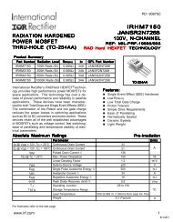
Figure 1. Block Diagram - Triple Output<br />
13<br />
+AUX.<br />
OUTPUT<br />
Vin<br />
1<br />
EMI<br />
FILTER<br />
12<br />
AUX.<br />
RETURN<br />
11<br />
-AUX.<br />
OUTPUT<br />
INHIBIT<br />
3<br />
UNDER VOLTAGE<br />
LOCKOUT<br />
& INHIBIT<br />
BIAS<br />
SUPPLY<br />
+5V<br />
+10.5V<br />
7<br />
6<br />
+MAIN<br />
MAIN<br />
RETURN<br />
LEVEL<br />
TRANSLATOR<br />
& FET DRIVE<br />
SHORT CIRCUIT<br />
&<br />
OVERLOAD<br />
RETURN<br />
2<br />
+5V<br />
+5V<br />
EA<br />
+<br />
-<br />
SYNC.<br />
4<br />
INPUT<br />
SYNC.<br />
5<br />
OUTPUT<br />
OSCILLATOR<br />
+<br />
PWM<br />
-<br />
RAMP<br />
GENERATOR<br />
SAMPLE<br />
&<br />
HOLD<br />
FEEDBACK<br />
TRIGGER<br />
10<br />
CASE<br />
GROUND<br />
6 www.irf.com
M3G-SERIES<br />
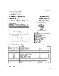
Figure 2. ±12V Load Regulation vs 5V Load<br />
14<br />
13.5<br />
±12V Magnitudes ( Volts )<br />
13<br />
12.5<br />
12<br />
11.5<br />
11<br />
5V load = 4A<br />
5V load = 2A<br />
5V load = 0.4A<br />
10.5<br />
10<br />
0 0.1 0.2 0.3 0.4 0.5 0.6 0.7 0.8 0.9 1<br />
±12V Load Current ( Amps each )<br />
Figure 3. ±15V Load Regulation vs 5V Load<br />
±15V Magnitudes ( Volts )<br />
18<br />
17.5<br />
17<br />
16.5<br />
16<br />
15.5<br />
15<br />
14.5<br />
14<br />
13.5<br />
13<br />
5V load = 4A<br />
5V load = 2A<br />
5V load = 0.4A<br />
0 0.1 0.2 0.3 0.4 0.5 0.6 0.7 0.8 0.9 1<br />
±15V Load Current ( Amps each )<br />
www.irf.com 7
M3G-SERIES<br />
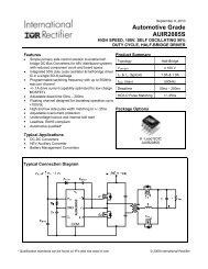
Figure 4. M3G280512T Efficiency vs Line and Load<br />
90<br />
80<br />
Efficiency ( % )<br />
70<br />
60<br />
Vin=18V<br />
Vin=28V<br />
50<br />
Vin=50V<br />
40<br />
0 5 10 15 20 25 30 35 40<br />
Output Power ( Watts )<br />
Figure 5. M3G280515T Efficiency vs Line and Load<br />
90<br />
80<br />
Efficiency ( % )<br />
70<br />
60<br />
Vin=18V<br />
Vin=28V<br />
50<br />
Vin=50V<br />
40<br />
0 5 10 15 20 25 30 35 40<br />
Output Power ( Watts )<br />
8 www.irf.com
M3G-SERIES<br />
Figure 6. Conducted Emissions, Positive Lead<br />
dB-uA<br />
100<br />
90<br />
80<br />
70<br />
60<br />
50<br />
40<br />
30<br />
20<br />
10<br />
CEO3 LIMIT<br />
0<br />
1E3 1E4 1E5 1E6 1E7 1E8<br />
Frequency ( Hz )<br />
Figure 7. Conducted Emissions, Return Lead<br />
100<br />
90<br />
80<br />
70<br />
dB-uA<br />
60<br />
50<br />
40<br />
30<br />
20<br />
10<br />
CEO3 LIMIT<br />
0<br />
1E3 1E4 1E5 1E6 1E7 1E8<br />
Frequency ( Hz )<br />
www.irf.com 9
M3G-SERIES<br />
Figure 8. Conducted Emissions, Common Mode<br />
dB-uA<br />
100<br />
90<br />
80<br />
70<br />
60<br />
50<br />
40<br />
30<br />
20<br />
10<br />
CEO3 LIMIT<br />
0<br />
1E3 1E4 1E5 1E6 1E7 1E8<br />
Frequency ( Hz )<br />
10 www.irf.com
M3G-SERIES<br />
Application Note:<br />
A) Attachment of the Converter.<br />
The following procedure is recommended for mounting the <strong>converter</strong> for optimum cooling and to circumvent<br />
any potential damage to the <strong>converter</strong>.<br />
Ensure that flatness of the plate where M3G <strong>converter</strong> to be mounted is no greater than 0.003” per linear inch.<br />
It is recommended that a thermally conductive gasket is used to promote the thermal transfer and to fill any<br />
voids existing between the two surfaces. IR recommends Sil-Pad 2000 with the thickness of 0.010". The<br />
shape of the gasket should match the footprint of the <strong>converter</strong> including the mounting flanges. The gasket<br />
is available from IR. The M3G-<strong>series</strong> <strong>converter</strong> requires either M3 or 4-40 size screws for attachment<br />
purposes.<br />
The procedure for mounting the <strong>converter</strong> is as follows:<br />
1. Check the mounting surfaces and remove foreign material, burrs if any or anything that may<br />
interfere with the attachment of the <strong>converter</strong>.<br />
2. Place the gasket on the surface reserved for the <strong>converter</strong> and line it up with the mounting holes.<br />
3. Place the <strong>converter</strong> on the gasket and line both up with mounting holes.<br />
4. Install screws using appropriate washers and tighten by hand (~ 4 in·oz) in the sequence shown below.<br />
5. Tighten the screws with an appropriate torque driver. Torque the screws up to 6 in·lb in the sequence<br />
shown above.<br />
www.irf.com 11
M3G-SERIES<br />
Mechanical Diagram<br />
3.055 MAX.<br />
0.500 2.00<br />
R0.0625<br />
4 places<br />
0.080<br />
Max.<br />
0.50<br />
0.20<br />
0.60<br />
1<br />
2<br />
3<br />
4<br />
5<br />
13<br />
12<br />
11<br />
10<br />
9<br />
8<br />
7<br />
6<br />
2.055<br />
MAX.<br />
2.30<br />
2.500<br />
0.30<br />
1.400<br />
Ref.<br />
0.200 Typ.<br />
Noncum.<br />
Pin<br />
Ø0.040<br />
0.45 1.10<br />
0.260<br />
3.50<br />
Ref.<br />
0.25<br />
FLANGE DETAIL<br />
0.25<br />
0.14<br />
R0.0625<br />
0.475<br />
MAX.<br />
0.40<br />
Tolerance : .XX ±0.01<br />
.XXX ±0.005<br />
Pin Designation (Triple Output)<br />
Pin # Designation Pin # Designation<br />
1 + Input 8 NC<br />
2 Input Return 9 NC<br />
3 Inhibit 10 Case Ground<br />
4 Sync. Input 11 - Aux. Output<br />
5 Sync. Output 12 Aux. Output Return<br />
6 Main Return 13 +Aux. Output<br />
7 + Main Output<br />
12 www.irf.com
M3G-SERIES<br />
Device Screening<br />
Requirement MIL-STD-883 Method No Suffix d CK d EM<br />
Temperature Range -55°C to +85°C -55°C to +85°C -55°C to +85°C<br />
Element Evaluation MIL-PRF-38534 Class K Class K N/A<br />
Non-Destructive Bond Pull 2023 Yes Yes N/A<br />
Internal Visual 2017 Yes Yes c<br />
Temperature Cycle 1010 Cond C Cond C Cond C<br />
Constant Acceleration 2001, Y1 Axis 3000 Gs 3000 Gs 3000 Gs<br />
PIND 2020 Cond A Cond A N/A<br />
Burn-In 1015<br />
320 hrs @ 125°C 320 hrs @ 125°C 48 hrs @ 125°C<br />
( 2 x 160 hrs ) ( 2 x 160 hrs )<br />
Final Electrical MIL-PRF-38534 -55°C, +25°C, -55°C, +25°C, -55°C, +25°C,<br />
( Group A ) & Specification +85°C +85°C +85°C<br />
PDA MIL-PRF-38534 2% 2% N/A<br />
Seal, Fine and Gross 1014 Cond A, C Cond A, C Cond A<br />
Radiographic 2012 Yes Yes N/A<br />
External Visual 2009 Yes Yes c<br />
Notes:<br />
c Best commercial practice.<br />
d CK is DSCC class K compliant without <strong>radiation</strong> performance. No Suffix is a <strong>radiation</strong> rated device but<br />
not available as a DSCC qualified SMD per MIL-PRF-38534.<br />
International Rectifier currently does not have a DSCC certified Radiation Hardness Assurance Program.<br />
Standard Microcircuit Drawing Equivalence Table<br />
Standard Microcircuit IR Standard<br />
Drawing Number Part Number<br />
5962-03226 M3G280512T<br />
5962-03227 M3G280515T<br />
Part Numbering<br />
M3G 28 05 15 T /EM<br />
Model<br />
Screening Level<br />
(Please refer to Screening Table)<br />
Nominal Input<br />
No Suffix, CK, EM<br />
Voltage<br />
28 = 28V<br />
Output<br />
T = Triple<br />
Main Output<br />
Auxiliary Output<br />
Voltage<br />
Voltage<br />
03R3 = 3.3V<br />
05 = ± 5V<br />
05 = 5V<br />
12 = ± 12V<br />
12 = 12V<br />
15 = ± 15V<br />
15 = 15V<br />
WORLD HEADQUARTERS: 233 Kansas St., El Segundo, California 90245, Tel: (310) 252-7105<br />
IR SAN JOSE: 2520Junction Avenue, San Jose, California 95134, Tel: (408) 434-5000<br />
Visit us at www.irf.com for sales contact information.<br />
Data and specifications subject to change without notice. 05/2010<br />
www.irf.com 13