- Page 1 and 2: CSD5 Servo Drive User Manual Catalo
- Page 3 and 4: Summary of Change You will see chan
- Page 5 and 6: Table Of Contents Summary of Change
- Page 7 and 8: iii Position Command Pulse . . . .
- Page 9 and 10: v Inspection and Protection Functio
- Page 11 and 12: Preface Read this preface to famili
- Page 13 and 14: Preface P-3 Combinational control m
- Page 15 and 16: Preface P-5 Manual Description Orde
- Page 17 and 18: Preface P-7 Installation and Wiring
- Page 19 and 20: Chapter 1 Before Using the CSD5 Ser
- Page 21 and 22: Before Using the CSD5 Servo Drive 1
- Page 23 and 24: Chapter 2 Installation This chapter
- Page 25 and 26: Installation 2-3 Use the Drive in a
- Page 27 and 28: Chapter 3 Wiring This chapter descr
- Page 29 and 30: Wiring 3-3 Table 3.1 Electric Circu
- Page 31 and 32: Wiring 3-5 Electric Circuit Diagram
- Page 33 and 34: Wiring 3-7 CAUTION Insert the wire
- Page 35 and 36: Wiring 3-9 Table 3.2 (I/O) Pin Arra
- Page 37 and 38: Wiring 3-11 Table 3.3 I/O Sequence
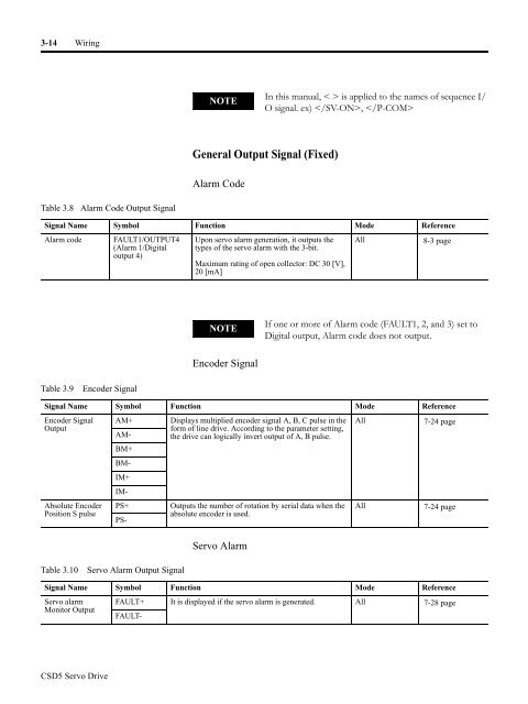
- Page 39: Wiring 3-13 (I/O) Output Signal Seq
- Page 43 and 44: Wiring 3-17 • PULS+ (15), PULS- (
- Page 45 and 46: Wiring 3-19 Whether to use the emer
- Page 47 and 48: Wiring 3-21 Connect to the relay ci
- Page 49 and 50: Wiring 3-23 Terminal Type The table
- Page 51 and 52: Wiring 3-25 Serial encoder connecti
- Page 53 and 54: Wiring 3-27 General Articles Wiring
- Page 55 and 56: Wiring 3-29 Cut-off features: 200 [
- Page 57 and 58: Wiring 3-31 Separate the input and
- Page 59 and 60: Wiring 3-33 Wiring when Using Sever
- Page 61 and 62: Chapter 4 Operator, Basic Setting a
- Page 63 and 64: Operator, Basic Setting and Startup
- Page 65 and 66: Operator, Basic Setting and Startup
- Page 67 and 68: Operator, Basic Setting and Startup
- Page 69 and 70: Operator, Basic Setting and Startup
- Page 71 and 72: Operator, Basic Setting and Startup
- Page 73 and 74: Operator, Basic Setting and Startup
- Page 75 and 76: Operator, Basic Setting and Startup
- Page 77 and 78: Operator, Basic Setting and Startup
- Page 79 and 80: Operator, Basic Setting and Startup
- Page 81 and 82: Operator, Basic Setting and Startup
- Page 83 and 84: Operator, Basic Setting and Startup
- Page 85 and 86: Chapter 5 Function for Control Mode
- Page 87 and 88: Function for Control Mode 5-3 Table
- Page 89 and 90: Function for Control Mode 5-5 Table
- Page 91 and 92:
Function for Control Mode 5-7 The t
- Page 93 and 94:
Function for Control Mode 5-9 TIP
- Page 95 and 96:
Function for Control Mode 5-11 Stan
- Page 97 and 98:
Function for Control Mode 5-13 When
- Page 99 and 100:
Function for Control Mode 5-15 Set
- Page 101 and 102:
Function for Control Mode 5-17 Elec
- Page 103 and 104:
Function for Control Mode 5-19 Redu
- Page 105 and 106:
Function for Control Mode 5-21 Exam
- Page 107 and 108:
Function for Control Mode 5-23 •
- Page 109 and 110:
Function for Control Mode 5-25 TIP
- Page 111 and 112:
Function for Control Mode 5-27 Para
- Page 113 and 114:
Function for Control Mode 5-29 Posi
- Page 115 and 116:
Function for Control Mode 5-31 Outp
- Page 117 and 118:
Function for Control Mode 5-33 Stan
- Page 119 and 120:
Function for Control Mode 5-35 TIP
- Page 121 and 122:
Function for Control Mode 5-37 Spee
- Page 123 and 124:
Function for Control Mode 5-39 Ther
- Page 125 and 126:
Function for Control Mode 5-41 Spee
- Page 127 and 128:
Function for Control Mode 5-43 Torq
- Page 129 and 130:
Function for Control Mode 5-45 Host
- Page 131 and 132:
Function for Control Mode 5-47 Exte
- Page 133 and 134:
Function for Control Mode 5-49 Caut
- Page 135 and 136:
Function for Control Mode 5-51 Torq
- Page 137 and 138:
Function for Control Mode 5-53 Stan
- Page 139 and 140:
Function for Control Mode 5-55 Tabl
- Page 141 and 142:
Function for Control Mode 5-57 Mult
- Page 143 and 144:
Function for Control Mode 5-59 Prec
- Page 145 and 146:
Chapter 6 Tuning by Gain Setting Th
- Page 147 and 148:
Tuning by Gain Setting 6-3 Applicab
- Page 149 and 150:
Tuning by Gain Setting 6-5 Unit App
- Page 151 and 152:
Tuning by Gain Setting 6-7 Gain Dia
- Page 153 and 154:
Tuning by Gain Setting 6-9 After au
- Page 155 and 156:
Tuning by Gain Setting 6-11 Precaut
- Page 157 and 158:
Tuning by Gain Setting 6-13 Once th
- Page 159 and 160:
Tuning by Gain Setting 6-15 Basic G
- Page 161 and 162:
Tuning by Gain Setting 6-17 Paramet
- Page 163 and 164:
Tuning by Gain Setting 6-19 Paramet
- Page 165 and 166:
Tuning by Gain Setting 6-21 Speed C
- Page 167 and 168:
Tuning by Gain Setting 6-23 Speed C
- Page 169 and 170:
Tuning by Gain Setting 6-25 Positio
- Page 171 and 172:
Tuning by Gain Setting 6-27 Tip to
- Page 173 and 174:
Tuning by Gain Setting 6-29 Paramet
- Page 175 and 176:
Tuning by Gain Setting 6-31 The fol
- Page 177 and 178:
Tuning by Gain Setting 6-33 CAUTION
- Page 179 and 180:
Tuning by Gain Setting 6-35 3. If i
- Page 181 and 182:
Tuning by Gain Setting 6-37 Therefo
- Page 183 and 184:
Tuning by Gain Setting 6-39 Categor
- Page 185 and 186:
Chapter 7 Applications This chapter
- Page 187 and 188:
Applications 7-3 The No. 4 pin of I
- Page 189 and 190:
Applications 7-5 DB Stop Method Set
- Page 191 and 192:
Applications 7-7 47 OUTPUT #3+ Rela
- Page 193 and 194:
Applications 7-9 Parameter Paramete
- Page 195 and 196:
Applications 7-11 Change the Motor
- Page 197 and 198:
Applications 7-13 Acceleration and
- Page 199 and 200:
Applications 7-15 The repeated freq
- Page 201 and 202:
Applications 7-17 Setting for Smoot
- Page 203 and 204:
Applications 7-19 Definition of S-c
- Page 205 and 206:
Applications 7-21 Speed Limiting Fu
- Page 207 and 208:
Applications 7-23 Accordingly, when
- Page 209 and 210:
Applications 7-25 Setting Value •
- Page 211 and 212:
Applications 7-27 The initial value
- Page 213 and 214:
Applications 7-29 Parameter Paramet
- Page 215 and 216:
Applications 7-31 Use of Absolute E
- Page 217 and 218:
Applications 7-33 Battery Battery I
- Page 219 and 220:
Applications 7-35 • When separate
- Page 221 and 222:
Applications 7-37 Encoder Servo Dri
- Page 223 and 224:
Applications 7-39 Multi-step rotati
- Page 225 and 226:
Applications 7-41 Operation Mode Fu
- Page 227 and 228:
Applications 7-43 Off-line Auto Tun
- Page 229 and 230:
Applications 7-45 Operation Sequenc
- Page 231 and 232:
Applications 7-47 Operation Sequenc
- Page 233 and 234:
Applications 7-49 Alarm Reset (run-
- Page 235 and 236:
Applications 7-51 How to Operate Re
- Page 237 and 238:
Applications 7-53 Table 7.9 Monitor
- Page 239 and 240:
Applications 7-55 Table 7.9 Monitor
- Page 241 and 242:
Chapter 8 Inspection and Protection
- Page 243 and 244:
Inspection and Protection Functions
- Page 245 and 246:
Inspection and Protection Functions
- Page 247 and 248:
Inspection and Protection Functions
- Page 249 and 250:
Inspection and Protection Functions
- Page 251 and 252:
Appedix B Parameter Group Parameter
- Page 253 and 254:
Parameter Group B-3 Reserved 0021 -
- Page 255 and 256:
Parameter Group B-5 Current Regulat
- Page 257 and 258:
Parameter Group B-7 Preset Velocity
- Page 259 and 260:
Parameter Group B-9 Disabled Brakin
- Page 261 and 262:
Parameter Group B-11 Range Value De
- Page 263 and 264:
Parameter Group B-13 Range Value De
- Page 265 and 266:
Parameter Group B-15 Applicable Ope
- Page 267 and 268:
Parameter Group B-17 Range for All
- Page 269 and 270:
Parameter Group B-19 Allocation of
- Page 271 and 272:
Parameter Group B-21 Applicable Ope
- Page 273 and 274:
Parameter Group B-23 1 Index Select
- Page 275 and 276:
Parameter Group B-25 Description Ru
- Page 277 and 278:
Parameter Group B-27 When Enabled I
- Page 279 and 280:
Parameter Group B-29 Applicable Ope
- Page 281 and 282:
Parameter Group B-31 Description
- Page 283 and 284:
Parameter Group B-33 On-line Vibrat
- Page 285 and 286:
Parameter Group B-35 2 nd Velocity
- Page 287 and 288:
Parameter Group B-37 3 rd Position
- Page 289 and 290:
Parameter Group B-39 4 th Velocity
- Page 291 and 292:
Parameter Group B-41 Range 0~5,000
- Page 293 and 294:
Parameter Group B-43 Preset Velocit
- Page 295 and 296:
Parameter Group B-45 Range Value De
- Page 297 and 298:
Parameter Group B-47 Range 1~32768
- Page 299 and 300:
Parameter Group B-49 Initial Value
- Page 301 and 302:
Parameter Group B-51 Applicable Ope
- Page 303 and 304:
Parameter Group B-53 Applicable Ope
- Page 305 and 306:
Parameter Group B-55 Range 20~1000
- Page 307 and 308:
Parameter Group B-57 Creep Velocity
- Page 309 and 310:
Parameter Group B-59 Indexing Gorup
- Page 311 and 312:
Parameter Group B-61 : : : : : : :
- Page 313 and 314:
Parameter Group B-63 Description If
- Page 315 and 316:
Parameter Group B-65 Range 0~65535
- Page 317 and 318:
Parameter Group B-67 Range 1~214748
- Page 319 and 320:
Parameter Group B-69 • Errors are
- Page 321 and 322:
Parameter Group B-71 Table E Error
- Page 323 and 324:
Parameter Group B-73 Table E Error
- Page 325 and 326:
Appendix C Specification and Exteri
- Page 327 and 328:
Specification and Exterior Size C-3
- Page 329 and 330:
Specification and Exterior Size C-5
- Page 331 and 332:
Appendix D Cable Specification PC C
- Page 333 and 334:
Appendix E I/O Setting and Indexing
- Page 335 and 336:
I/O Setting and Indexing E-5 Sequen
- Page 337 and 338:
I/O Setting and Indexing E-7 I/O Se
- Page 339 and 340:
I/O Setting and Indexing E-9 I/O Si
- Page 341 and 342:
I/O Setting and Indexing E-11 PAUSE
- Page 343 and 344:
I/O Setting and Indexing E-13 STOP
- Page 345 and 346:
I/O Setting and Indexing E-15 Index
- Page 347 and 348:
I/O Setting and Indexing E-17 Start
- Page 349 and 350:
I/O Setting and Indexing E-19 Homin
- Page 351 and 352:
I/O Setting and Indexing E-21 Homin
- Page 353 and 354:
I/O Setting and Indexing E-23 Veloc
- Page 355 and 356:
I/O Setting and Indexing E-25 Speed
- Page 357 and 358:
I/O Setting and Indexing E-27 Movin
- Page 359 and 360:
I/O Setting and Indexing E-29 RUN S
- Page 361 and 362:
I/O Setting and Indexing E-31 31 CS
- Page 363:
Copyright © 2011 RS Automation Co.