

geostationary telecommunications satellites electronic telephone set ...
geostationary telecommunications satellites electronic telephone set ...
geostationary telecommunications satellites electronic telephone set ...

Create successful ePaper yourself
Turn your PDF publications into a flip-book with our unique Google optimized e-Paper software.
ERICSSON<br />
REVIEW<br />
3<br />
1976<br />
GEOSTATIONARY TELECOMMUNICATIONS SATELLITES<br />
ELECTRONIC TELEPHONE SET-ERICOFON 700<br />
CCM-A WELL-TRIED AND ECONOMIC MAINTENANCE SYSTEM<br />
CCM IN THE DUTCH TELEPHONE NETWORK<br />
OPTIMIZATION OF POWER SUPPLY EQUIPMENT<br />
DEVELOPMENT AND PRODUCTION OF SOFTWARE FOR AKE 13
ERICSSON REVIEW<br />
NUMBER 3 • 1976 • VOLUME 53<br />
Copyright Telefonaktiebolaget LM Ericsson<br />
Printed in Sweden, Stockholm 1976<br />
RESPONSIBLE PUBLISHER DR. TECHN. CHRISTIAN JACOB/EUS<br />
EDITOR GUSTAF 0. DOUGLAS<br />
EDITORIAL STAFF FOLKE BERG<br />
BO SEIJMER (WORLDWIDE NEWS)<br />
EDITOR'S OFFICE S-126 25 STOCKHOLM<br />
SUBSCRIPTION ONE YEAR $6.00, ONE COPY $1.70<br />
Contents<br />
110 • Geostationary Telecommunications Satellites<br />
118 • Electronic Push-button Telephone Set — ERICOFON 700<br />
134 • CCM — A Well-tried and Economic Maintenance System<br />
138 • Ten Years Experience of CCM in the Dutch Telephone Network<br />
142 • Optimization of Power Supply Equipment for Modern<br />
Telecommunication Systems<br />
152 • Development, Production and Maintenance of Software for AKE 13<br />
161 • WORLDWIDE NEWS<br />
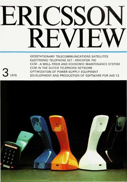
COVER<br />
ERICOFON 700 — A modern <strong>electronic</strong><br />
push-button <strong>telephone</strong> <strong>set</strong>
Geostationary<br />
Telecommunications Satellites<br />
Harold A. Rosen<br />
At a ceremony held at the Museum of Technology in Stockholm on May 5th,<br />
1976 the LM Ericsson Prize was awarded for the first time. The recipient<br />
was Dr. Harold A. Rosen from Los Angeles.<br />
The prize and the prizewinner were introduced by the Chairman of the Prize<br />
Committee, Dr. Hkkan Sterky, whose introduction can be summarized<br />
as follows:<br />
In 1975 the LM Ericsson Board of directors decided to institute a prize of 100,000<br />
Swedish crowns for significant contributions within <strong>telecommunications</strong><br />
engineering. According to the statutes the prize shall be awarded every third<br />
year to a person who in the last three-year period has made an specially<br />
important scientific or technological contribution within <strong>telecommunications</strong><br />
engineering or who has earlier made such contributions which, in the course<br />
of the period, have proved to be of this nature.<br />
The Prize Committee consists of three members and works quite independently<br />
of the LM Ericsson Board of directors and President, and is sovreign in its<br />
selection of prizewinner. Candidates are to be nominated before October 1st<br />
the year before the prize is awarded. In 1974, 74 candidates were nominated<br />
by 47 experts in the field of <strong>telecommunications</strong> engineering.<br />
Dr. Rosen was born in New Orleans, Louisiana, in 1926 and studied at Tulane<br />
University and California Institute of Technology. He is now vice president<br />
of Huges Aircraft Company, Space and Communications Group. He holds<br />
a number of patents and has been awarded many honorary distinctions.<br />
After the introduction Dr. Rosen presented a paper on <strong>geostationary</strong><br />
<strong>telecommunications</strong> <strong>satellites</strong>, which is presented here. At the subsequent<br />
prize ceremony the LM Ericsson Prize was presented to Dr. Rosen by<br />
King Carl XVI Gustaf.<br />
UDC 621 396 546<br />
629.783<br />
LME 858<br />
Geostationary <strong>telecommunications</strong> <strong>satellites</strong><br />
have resulted from a successful<br />
blend of controllable rocket and radio<br />
repeater technologies. The creative<br />
ideas and thoughtful experiments of<br />
many men from many countries have<br />
yielded the engineering basis of today's<br />
spacecraft, and I would like to<br />
pay tribute to a few of them while recounting<br />
the significant events leading<br />
to the global and domestic systems<br />
currently in use.<br />
Before describing the <strong>satellites</strong>, a few<br />
words about the launch vehicles are<br />
appropriate. The efficient launchers<br />
now in use owe their origins to the<br />
early rocket experimenters. Although<br />
solid propellant rockets have been<br />
known and used for centuries, it remained<br />
for the theoretical studies and<br />
test firings of gyroscopically controlled<br />
rockets in the 1920's and 1930's by the<br />
American university professor Robert<br />
H. Goddard to demonstrate the feasibility<br />
of liquid propulsion, the primary<br />
propulsion system of most of today's<br />
launch vehicles, which for communications<br />
<strong>satellites</strong> are primarily Delta and<br />
Centaur rockets. In a theoretical paper<br />
in 1929, the Austrian engineer Hermann<br />
Noordung gave the first description of<br />
the properties of the <strong>geostationary</strong> orbit.<br />
He showed that if a satellite were<br />
rocketed into a circular equatorial<br />
orbit at an altitude of 36,000 kilometers,<br />
where its orbital period would be 24<br />
hours, it would appear stationary relative<br />
to the earth, as if supported by a<br />
gigantic tower.<br />
The first description of a communications<br />
satellite system is due to the prophetic<br />
vision of the English scientist<br />
and writer Arthur C. Clarke, who in<br />
1945 showed how if suitable radio<br />
equipment were placed in a <strong>geostationary</strong><br />
orbit it could provide continuous<br />
worldwide radio coverage. He<br />
recognized not only the possibility of<br />
satellite communications but its importance<br />
to the world and proposed<br />
that such a system be developed.<br />
The American scientist and engineer J.<br />
R. Pierce described long distance<br />
communications systems based on<br />
orbiting radio relays of various types<br />
and altitudes in a paper published in<br />
1955, the last sentence of which reads,<br />
"At this point, some information from<br />
astronomers about orbits and from<br />
rocket men about constructing and<br />
placing <strong>satellites</strong> would be decidedly<br />
welcome." Two years later, the Russian<br />
rocket men partly satisfied his curiosity<br />
with the launching of Sputnik, the<br />
first artificial satellite.<br />
This starting event in 1957 stimulated<br />
more activity than any other toward<br />
the realization of practical spacecraft.<br />
Among other things, it led to the beginning<br />
of a large American space<br />
program and the awareness on the<br />
part of many, previously oblivious to<br />
space, of its promise. I was one of<br />
those so stimulated, and while perusing<br />
the subject in 1959, I came<br />
across an elaboration by Dr. Pierce<br />
and Rudolph Kompfner on transoceanic<br />
communication by satellite. This article<br />
described many configurations,<br />
including the <strong>geostationary</strong> system<br />
previously envisioned by Clarke, and<br />
pointed out its benefits as well as some<br />
of its Droblems.
111<br />
HAROLD A. ROSEN<br />
Vice President<br />
Hughes Aircraft Company, USA<br />
In contrast to all other orbits, the <strong>geostationary</strong><br />
orbit permits continuous<br />
communications over vast areas via a<br />
single satellite and requires little, if<br />
any, tracking capability in the associated<br />
earth terminals. Thus, potentially<br />
large cost savings in both the orbiting<br />
and earthbased elements of a<br />
satellite communications system would<br />
accrue when <strong>geostationary</strong> <strong>satellites</strong><br />
were available. However, in 1959 the<br />
prospects of early achievement of this<br />
goal were bleak. Many problems resulted<br />
from the size and complexity of<br />
the designs then being considered.<br />
The large size precluded the use of<br />
launch vehicles available at that time;<br />
but, even if launchable, these designs<br />
were too complex to have an economically<br />
attractive life expectancy.<br />
While pondering these matters, it occurred<br />
to me that the satellite's size<br />
and complexity could be greatly reduced<br />
if a spinning configuration were<br />
adopted. This would provide stabilization<br />
of a toroidal antenna beam which<br />
continuously encompassed the earth,<br />
simplifying the attitude control, while<br />
permitting orbital period control by use<br />
of spin phased impulses, thus simplifying<br />
the orbit control system. Additional<br />
savings in weight could be<br />
achieved by the use of a solid state<br />
receiver for the communications receiver<br />
and a traveling wave tube amplifier<br />
for the transmitter, an invention<br />
of Kompfner's perfected by Pierce.<br />
These design concepts provided the<br />
basis for a lightweight <strong>geostationary</strong><br />
communications satellite design; and,<br />
starting in the fall of 1959, I led a small<br />
team charged with perfecting and reducing<br />
it to practice. My late colleaugue,<br />
Donald Williams, was responsible<br />
for the orbit and attitude control<br />
system design and analysis, and,<br />
among many other contributions, invented<br />
a method of attitude control<br />
using a single thruster, which he demonstrated<br />
with a dynamic model in<br />
1960. The entire attitude and orbit control<br />
of the satellite could now be accomplished<br />
with only two thrusters,<br />
using spin phased impulses when necessary.<br />
My friend and coworker, Thomas<br />
Hudspeth, was responsible for the<br />
receiver and antenna development and<br />
designed efficient, lightweight elements<br />
years ahead of their time. John<br />
Mendel adapted the traveling wave<br />
tube transmitter to space applications<br />
by perfecting a rugged, lightweight<br />
design featuring metal-ceramic construction<br />
and periodic permanent magnet<br />
focusing. With these elements, we<br />
proceeded to construct and test a prototype<br />
<strong>geostationary</strong> satellite during<br />
the year 1960, an effort supported by<br />
Hughes Aircraft Company, and also<br />
began a campaign to get it launched.<br />
Our initial proposals were turned down<br />
by all U.S. Government agencies and<br />
every communications company that<br />
was approached. An unsuccessful attempt<br />
to interest European agencies<br />
and communications companies in the<br />
idea centered on the Paris Air Show of<br />
1961 and a subsequent demonstration<br />
on the Eiffel Tower, where it was alleged<br />
that "this is as high as it will ever<br />
get". The general feeling of skepticism<br />
expressed both in the United States<br />
and Europe involved doubts about the<br />
technical approach as well as the quality<br />
of voice communications via a <strong>geostationary</strong><br />
satellite. The latter objection<br />
was raised because of the propagation<br />
time delay associated with the<br />
high altitude orbit, and its adverse interaction<br />
with the echo suppressors<br />
used in the ground networks. However,<br />
continued tests on this question showed<br />
that the time delay could be acceptable<br />
when the voice circuits were<br />
equipped with properly designed echo<br />
suppressors, and was of no consequence<br />
for television and telegraphic<br />
communications.<br />
After additional persuasion, late in<br />
1961 the U.S. Space Agency, NASA,<br />
with cooperation from the Department<br />
of Defense, sponsored a program to<br />
test the concept—this became known<br />
as the Syncom program, for Synchronous<br />
Communications. While the flight<br />
models of Syncom were being constructed<br />
and tested in the summer of<br />
1962, Telstar, which was constructed<br />
by Bell Telephone Laboratories of<br />
AT&T, was launched by NASA into a<br />
low altitude orbit and first demonstrated<br />
the feasibility of wideband transoceanic<br />
communications via satellite.<br />
The first Syncom satellite was launched<br />
in February 1963 but exploded when<br />
injected into final orbit and became
112<br />
forever silent. The next launch attempt<br />
was made that July. Everything worked<br />
perfectly on Syncom II, and communications<br />
was successfully demonstrated<br />
via a synchronous but not <strong>geostationary</strong><br />
satellite (since the orbit was<br />
inclined relative to the equator). The<br />
first <strong>geostationary</strong> orbit was achieved<br />
in 1964 with the launch of Syncom III<br />
into an equatorial synchronous orbit;<br />
among other things, it carried television<br />
transmissions of the Tokyo Olympics<br />
across the Pacific.<br />
Coincident with the first Syncom<br />
launch, the U.S. Comsat Corporation<br />
was formed for the purpose of engaging<br />
in commercial communications<br />
via satellite. Noting the success of<br />
Syncom, Comsat entered into a contract<br />
for the construction of an experimental<br />
operational satellite of similar<br />
design to be used in transatlantic<br />
service by INTELSAT, the International<br />
Telecommunications Satellite Consortium<br />
(now Organization), which would<br />
be formed in time to use the new satellite.<br />
In the spring of 1965, Intelsat I,<br />
also known as Early Bird, was launched<br />
and inaugurated commercial intercontinental<br />
communications of voice,<br />
telegraph, and television traffic via<br />
satellite.<br />
While Early Bird was being constructed,<br />
NASA was sponsoring the development<br />
of still higher performance<br />
<strong>satellites</strong> in its Applications Technology<br />
Satellite series. Additional communications<br />
capacity could be achieved<br />
by using pencil beam antennas to<br />
replace the lower gain toroidal beam<br />
heretofore used. The ATS <strong>satellites</strong><br />
demonstrated both <strong>electronic</strong> and<br />
mechanical means of despinning these<br />
beams to illuminate the earth continuously<br />
from the spinning satellite. The<br />
ATS satellite also took the first pictures<br />
of the full disc of the earth from synchronous<br />
orbit by use of a spin-scan<br />
cloud camera. Early Bird was followed<br />
in 1966 by Intelsat II, a larger and<br />
slightly higher capacity satellite, and<br />
in 1968 by Intelsat III, which featured<br />
a mechanically despun pencil beam<br />
antenna and completed the first truly<br />
global system for INTELSAT with yet<br />
higher capacity.<br />
In 1969 an experimental high<br />
power<br />
satellite designed to provide service<br />
to ships and airplanes was launched<br />
by the U.S. Department of Defense.<br />
Called TACSAT, it featured a new dual<br />
spin configuration which provided<br />
greater flexibility in the communications<br />
and mechanical design areas<br />
than the earlier spinners by relaxing<br />
some of the geometric constraints.<br />
The method of stabilizing this configuration<br />
was invented by Anthony<br />
lorillo. This design feature was incorporated<br />
into the high capacity Intelsat<br />
IV series which began service in 1971,<br />
and whose six currently operating <strong>satellites</strong><br />
carry the bulk of INTELSAT'S<br />
traffic. The Intelsat orbiting fleet is at<br />
present being augmented by the still<br />
further advanced and higher capacity<br />
Intelsat IVA, two of which have been<br />
launched within the last few months.<br />
The additional capacity of Intelsat IVA<br />
was achieved by the development of a<br />
multibeam antenna with east-west<br />
isolation, which makes it possible to<br />
reuse the frequency spectrum. The<br />
antenna, its feed distribution system,<br />
and the transmitter compartment are<br />
today's standard for satellite engineering.<br />
The Intelsat <strong>satellites</strong> currently<br />
carry all transoceanic television and<br />
most of the international telephonic<br />
communications, in conjunction with a<br />
complex of 123 earth stations located<br />
in 71 of the 92 member nations of IN<br />
TELSAT.<br />
As the economy of communications<br />
via satellite steadily improved through<br />
technological change in the Iate1960's,<br />
it became apparent that not only international<br />
but also intranational communication<br />
could be achieved on a cost<br />
competitive basis by use of <strong>satellites</strong><br />
in certain countries. Canada became<br />
the first country to implement a national<br />
satellite system with the inaugural<br />
use of Anik by its Telesat Corporation<br />
in 1972. The large antenna used<br />
on Anik generated an antenna beam<br />
which concentrated much of the satellite's<br />
radiation within the borders of<br />
Canada, thus providing substantial<br />
communications capacity via a relatively<br />
small and low cost satellite. The<br />
three Anik <strong>satellites</strong> now provide dual<br />
language television distribution and<br />
thin-route telephonic service to the<br />
sparsely populated portions of Canada,<br />
as well as conventional communica-
113<br />
tions service to the more densely<br />
populated areas. The Western Union<br />
Company has provided general communications<br />
service to the United<br />
States since the launch of a similar<br />
satellite, called Westar, in 1974. Indonesia<br />
is currently implementing the<br />
ground terminals for its national system<br />
which is expected to begin operations<br />
following the launch of its first<br />
satellite, called Palapa, in July of this<br />
year.<br />
In addition to international and national<br />
communications systems, <strong>satellites</strong><br />
are expected to play an increasing<br />
role in providing mobile communications<br />
service to ships and airplanes.<br />
TheMarisat satellite launched thisyear<br />
in February has begun service to U.S.<br />
Navy ships on a regular basis, and<br />
service will be offered to commercial<br />
shipping later this year when additional<br />
Marisats are planned to be in<br />
operation.<br />
Since the signals from national <strong>satellites</strong><br />
can be concentrated within a nation's<br />
boundaries, smaller antennas<br />
can be used at earth terminals than for<br />
<strong>satellites</strong> whose energy is more widely<br />
dispersed. This fact, coupled with the<br />
steady improvement in the performance<br />
of low cost receivers, has made<br />
it possible to build television reception<br />
terminals at a small fraction of the<br />
cost of general-purpose international<br />
terminals, and these costs are rapidly<br />
decreasing. Thus, widespread television<br />
distribution via national satellite<br />
systems for education and cultural enrichment<br />
is becoming steadily more<br />
attractive economically, and this use<br />
of satellite communications may yet<br />
become the most important application<br />
of all for <strong>geostationary</strong> communications<br />
<strong>satellites</strong>.<br />
The figures on pages 114—777 illustrated<br />
Dr. Rosen's paper.
114<br />
Figs. 1—4 Figs. 5—8
Figs. 9—12 Figs. 13—16<br />
115
116<br />
Figs. 17—20 Figs. 21—24
Figs. 25—28 Figs. 29—32<br />
117
Electronic<br />
Push-button Telephone Set<br />
-ERICOFON700<br />
Arne Boeryd, Leif Branden, Jan-Olof Hedman and Olle Larsson<br />
The <strong>telephone</strong> <strong>set</strong>s designed by LM Ericsson in 1892 and 1931 were trend-<strong>set</strong>ters.<br />
The <strong>set</strong>s used today by <strong>telephone</strong> administrations all over the world are<br />
developments of the 1931 model. Naturally there are differences as regards<br />
design and construction, but the basic features are the same. LM Ericsson's<br />
latest design on the lines of this basic model is the well-known <strong>telephone</strong> <strong>set</strong><br />
DIALOG, which was introduced on the international market in 1962.<br />
LM Ericsson's one-piece <strong>set</strong> ERICOFON, which was introduced in 1956,<br />
was a pioneer not only because of its unique and functional shape but primarily<br />
because this model enabled the <strong>telephone</strong> administrations to offer the<br />
subscribers an alternative to the traditional type of <strong>set</strong>. The commercial success<br />
evinced by ERICOFON is the best proof of the subscribers' appreciation of<br />
the appearance, technical quality and easy handling of the <strong>set</strong>.<br />
UDC 621.395.721:<br />
621.395.6361<br />
LME 822<br />
Design requirements<br />
The technical development of material<br />
and components that took place up to<br />
a few years ago continuously affected<br />
the <strong>telephone</strong> <strong>set</strong>s, which were revised<br />
and improved. However, this continuous<br />
development did not usually provide<br />
scope for the introduction of<br />
completely new techniques or for offering<br />
new services and facilities.<br />
However, the landslide development<br />
that has taken place in semiconductor<br />
engineering during the last few years<br />
has meant that <strong>telephone</strong> subscribers<br />
can now be offered several new facilities<br />
and greatly improved transmission<br />
quality in the <strong>telephone</strong> <strong>set</strong>, irrespective<br />
of to which subscriber line or local<br />
exchange the subscriber is connected.<br />
Hitherto it has only been possible to<br />
offer push-button dialling to a limited<br />
number of subscribers, connected to<br />
new or modified local exchanges. The<br />
results of field trials and the enthusiastic<br />
reception push-button dialling has<br />
received in the countries (the U.S. and<br />
Canada) where it has been offered for<br />
some time as an alternative to conventional<br />
dialling, testify to the advantages<br />
the method gives the subscriber. Impulsing<br />
is faster, more reliable and<br />
easier from the subscriber's point of<br />
view, and at the same time the register<br />
holding time in the exchange is reduced,<br />
with increased availability in<br />
the <strong>telephone</strong> network as a result.<br />
The development of memory and counter<br />
circuits in MOS technology has<br />
paved the way for the possibility of<br />
transforming a push-button code to<br />
decadic impulsing at an arbitrary frequency<br />
(10—20 Hz). This development<br />
makes it possible to offer all subscrib-<br />
Fig. 1<br />
ERICOFON 700
119<br />
ARNE BOERYD<br />
LEIF BRANDEN<br />
JAN-OLOF HEDMAN<br />
OLLE LARSSON<br />
Subscriber Equipment Division<br />
Telefonaktiebolaget LM Ericsson<br />
ers push-button dialling, irrespective<br />
of the type of local exchange. A new<br />
<strong>telephone</strong> <strong>set</strong> can therefore be designed<br />
for only push-button dialling.<br />
The transmission components in the<br />
<strong>telephone</strong> <strong>set</strong>s have been subjected to<br />
intense revision work during the last<br />
few years. This applies both as regards<br />
the microphone and the receiver, and<br />
also the transmission circuits. The<br />
work has resulted in a miniaturized<br />
microphone and receiver, and a replacement<br />
for the passive speech circuit<br />
has been developed, an <strong>electronic</strong><br />
speech circuit with the necessary active<br />
amplifier elements integrated with<br />
the required passive piece parts.<br />
Fig. 2<br />
ERICOFON 700, exploded view
The bottom part (frame) ot the <strong>set</strong><br />
Push-button dialling mechanism<br />
1. Common contact spring assembly<br />
2. Slide<br />
3. Switching bar<br />
Fig. 5<br />
Cradle switch mechanism<br />
1. Contact spring assembly<br />
2. Arms<br />
3. Return spring<br />
4. Switching bar<br />
5. Cradle key<br />
6. Switching bar<br />
7. Cradle buttons<br />
The signalling device of the <strong>telephone</strong><br />
<strong>set</strong>, the bell, has in certain cases already<br />
been replaced by a tone ringer,<br />
either with a separate electroacoustic<br />
signal generator or with the receiver<br />
or microphone as the sound transmitter.<br />
The advantages of tone ringing are<br />
a more pleasant but at the same time<br />
more penetrating signal, and a unit<br />
that, from the design point of view, requires<br />
less space than a conventional<br />
bell.<br />
Apart from the advantages as regards<br />
function and quality, a design using<br />
modern <strong>electronic</strong> technology with integrated<br />
circuits also means a substantial<br />
reduction in the weight of the <strong>set</strong>.<br />
In connection with the centenary of the<br />
<strong>telephone</strong> and of LM Ericsson, the<br />
company introduced the first wholly<br />
<strong>electronic</strong> one-piece <strong>telephone</strong> <strong>set</strong>.<br />
The exterior of the <strong>set</strong> has the classical<br />
shape of ERICOFON.<br />
Mechanical design and<br />
construction<br />
The new <strong>telephone</strong> <strong>set</strong>, ERICOFON<br />
700, consists of two main parts, the<br />
bottom part and the case. The bottom<br />
part contains the push-button <strong>set</strong>,<br />
cradle mechanism including the cradle<br />
contact spring assembly, microphone,<br />
transmission printed board assembly<br />
and a ring unit. The case holds<br />
the impulsing printed board assembly<br />
and receiver.<br />
Two characteristic features of all subcomponents<br />
in ERICOFON 700 are low<br />
weight and smali volume. Special attention<br />
has been paid to the design of<br />
the cradle mechanism and the cradle<br />
contact spring assembly in order to<br />
achieve both low weight and high reliability<br />
even if the <strong>set</strong> is placed on an<br />
uneven surface.<br />
A one-piece <strong>set</strong> with all components<br />
in the "hand<strong>set</strong>" puts great demands<br />
on the mechanical stability of the <strong>set</strong>.<br />
The main construction principle has<br />
therefore been to make the <strong>set</strong> and the<br />
mountings for the various parts relatively<br />
elastic in relation to each other<br />
in order to provide shock absorption.<br />
The various units of the <strong>set</strong> consist of<br />
functional blocks that can be tested<br />
individually during manufacture and<br />
replaced individually during maintenance.<br />
The construction of the <strong>set</strong> is shown in<br />
detail in fig. 2.<br />
As has already been mentioned, the<br />
<strong>set</strong> consists of two main parts, insert<br />
(bottom part) and case. The two parts<br />
plug into each other and are held together<br />
by three screws.<br />
THE INSERT<br />
The insert consists of the following<br />
parts:<br />
• Frame with gasket<br />
Push-button dialling mechanism<br />
• Cradle mechanism<br />
• Recall button (R)<br />
] Transmission unit<br />
n Ring unit<br />
• Cord<br />
Frame with gasket<br />
The frame, fig. 3, supports all the structural<br />
parts of the <strong>set</strong>. The frame has<br />
been designed with regard to the<br />
stringent mechanical strength requirements.<br />
It is injection moulded in ABS<br />
plastic. The frame is always black<br />
irrespective of the colour of the case.<br />
In order to protect the surface on<br />
which the <strong>set</strong> is placed, the underside<br />
of the frame is provided with a gasket<br />
made of injection moulded polyuretane,<br />
a material that does not affect or<br />
discolour varnished surfaces.<br />
Push-button dialling mechanism<br />
During the 1960s LM Ericsson developed<br />
a push-button dialling mechanism<br />
for the internationally recommended<br />
V.F. code signalling system.<br />
This mechanism, has previously been<br />
described in Ericsson Review'. At that<br />
time there were several other pushbutton<br />
dialling systems in existence,<br />
with different "dialling" mechanisms.<br />
The production volumes per system<br />
were fairly small, which meant that<br />
special push-button <strong>set</strong>s were rather<br />
expensive.
121<br />
Fig. 6<br />
Cradle contact spring assembly<br />
1. Frame<br />
2. Contact strip<br />
3. Contact springs<br />
4. Spacer<br />
5. Camshaft<br />
6. Lid<br />
7. Screw<br />
During the development of ERICOFON<br />
700 the basic principle was therefore<br />
adopted that it should be possible<br />
to use the same push-button dialling<br />
mechanism for all existing automatic<br />
<strong>telephone</strong> systems. The mechanism<br />
works in accordance with the same<br />
principles as that for V.F. code signalling.<br />
In the impulsing unit push-button<br />
signals are converted to the signalling<br />
codes of the various automatic <strong>telephone</strong><br />
systems—V.F. code, d.c. impulsing<br />
(instead of a conventional dial)<br />
etc.<br />
Cradle mechanism<br />
The cradle mechanism (fig. 5) is activated<br />
at three points, which are<br />
placed symmetrically around the pushbutton<br />
dialling mechanism, namely by<br />
a long key on the front of the <strong>set</strong>, which<br />
activates the two switching bars and<br />
also by two buttons in the rear part of<br />
the <strong>set</strong>, which operate one switching<br />
bar each. The vertical movement of the<br />
cradle buttons is transformed by the<br />
switching bars into a torsional movement,<br />
which is transferred to the actuating<br />
device of the cradle contact<br />
spring assembly.<br />
Cradle contact spring assembly<br />
The requirements regarding low weight<br />
for ERICOFON 700, compact structure<br />
and a large number of contact functions,<br />
led to a new design of the contact<br />
spring assembly. The design requirements<br />
for this unit were:<br />
— small dimensions<br />
— low operating force<br />
—• large movement margins before<br />
and after contact occurrences<br />
— contact functions consisting of<br />
four changeovers, alternatively four<br />
make-before-break contacts with<br />
requirements for time sequence between<br />
the contact occurrences<br />
— a design adapted for mounting on<br />
a printed circuit board.<br />
The contact spring assembly, fig. 6,<br />
contains four separate break contacts<br />
and four separate make contacts,<br />
which can be connected to form four<br />
make-before-break or changeovers. By<br />
changing the camshaft, within the<br />
limits of eight contact functions, the<br />
desired number of closures, breaks<br />
or changeovers can be obtained, fig. 7.<br />
The construction of the contact spring<br />
assembly, with a turning camshaft that<br />
works upon the springs, makes possible<br />
large movement margins both before<br />
and after the contact occurrences<br />
without requiring largeractuating force<br />
or increasing the stress on the springs.<br />
The desired time sequence of the<br />
various contact occurrences is obtained<br />
through a suitable design of the<br />
camshaft, fig. 11.<br />
In view of the low voltage of <strong>electronic</strong><br />
circuits, silver palladium contacts are<br />
used.
Fig. 10<br />
Buzzer unit<br />
Fig. 9<br />
Tone ringing unit<br />
Recall button (R button),<br />
number frame<br />
In order to simplify the operation of the<br />
<strong>set</strong> as much as possible it was necessary<br />
to reduce the number of function<br />
elements to a minimum. For this reason<br />
the number frame and the recall<br />
button have been combined to form<br />
one unit.<br />
Pos. 1 in fig. 2 shows the button for<br />
calling a register. The number frame,<br />
pos. 2, is mounted over the R button<br />
with one end carried in a bearing. The<br />
R button is actuated by pressure on<br />
the other end of the number frame. In<br />
these cases where the R button is not<br />
required, the number frame is fixed.<br />
The number frame is mounted with the<br />
aid of a snap-on device on the frame.<br />
Transmission circuit unit<br />
Pos. 3 in fig. 2 shows the transmission<br />
circuit unit, fig. 8. The unit contains the<br />
<strong>electronic</strong> speech circuit, electret microphone<br />
and cradle contact spring assembly.<br />
The electret microphone and<br />
the speech circuit are mounted in a<br />
common plastic cover. The cover is<br />
injection moulded. The speech circuit<br />
is protected against amplitude modulated<br />
radio signals. The transmission<br />
circuit also contains the necessary<br />
connection screws for the instrument<br />
cord.<br />
The printed circuit board is a doublefoil<br />
board of glass fibre reinforced<br />
epoxy laminate with plated-through<br />
holes.<br />
Ring unit<br />
The ring unit (pos. 4 in fig. 2) is available<br />
in three alternative versions: for<br />
tone ringing, with an electromechanical<br />
buzzer and as a connection unit<br />
without any internal calling device (an<br />
external calling device, not associated<br />
with the <strong>set</strong>, is used). The ring unit always<br />
contains the jack that connects<br />
the insert of the <strong>set</strong> with the impulsing<br />
<strong>electronic</strong>s and the receiver, which<br />
are mounted in the case. Fig. 9 shows<br />
the tone ringing unit and fig. 10 the unit<br />
for electromechanical buzzer.<br />
Telephone cord<br />
The <strong>telephone</strong> cord (pos. 12 in fig. 2) is<br />
of a standard type with colour-coded<br />
tinsel conductors with a PVC sheath.<br />
Each conductor consists of four-wire,<br />
double-tape cadmium-copper tapes<br />
wound round a polyester core. A part<br />
of the cord is coiled and its normal<br />
length is 1.3 m. Fully extended it measures<br />
2.4 m. It is fixed to the frame with<br />
mechanical stress relief. The connectors<br />
are terminated in cable lugs for<br />
screw connection.<br />
Mounting the insert<br />
The push-button dialling mechanism is<br />
screwed into the frame with the aid of<br />
two distance pieces which also constitute<br />
the holders for the transmission<br />
Fig. 8<br />
Transmission unit<br />
Fig. 7<br />
Cradle contact assembly, wiring diagram<br />
MAKE-BEFORE-BREAK CONTACT<br />
1 and 3 or 1 and 4 are connected together.<br />
When the camshaft turns, 1 and 2 close before<br />
3 and 4 break<br />
ORDINARY CHANGEOVER<br />
2 and 3 or 1 and 4 are connected together.<br />
When the camshaft turns, 3 and 4 break before 1<br />
and 2 close
123<br />
Fig. 11<br />
Cradle contact spring assembly, functional<br />
diagram<br />
Y///A<br />
Closed contacts<br />
A a Torsional angle of the camshaft when It<br />
turns from position 1 to position 2
Fig. 12<br />
Impulsing unit<br />
and ring units. Between the transmission<br />
unit and the ring unit a spacer has<br />
been inserted, which insulates the two<br />
printed board assemblies from each<br />
other.<br />
CASE<br />
The case contains the impulsing <strong>electronic</strong>s,<br />
the receiver with the associated<br />
cap and a fixing device for these.<br />
The case and receiver cap are made<br />
of injection moulded ABS plastic in<br />
several different colours.<br />
Impulsing unit<br />
Pos. 5, fig. 2 shows the impulsing unit.<br />
The printed circuit board is made of<br />
glass fibre reinforced epoxy laminate<br />
with copper foil for conductive patterns<br />
on both sides and with platedthrough<br />
holes for the components.<br />
Both the printed board assemblies for<br />
decadic pulse signalling and the one<br />
for V.F. code signalling are encased in<br />
a shrink tube. Thus the components<br />
are well protected against mechanical<br />
shocks to which the <strong>set</strong> may be subjected.<br />
The printed board assembly contains<br />
a spring holder for the receiver (pos. 6<br />
and 7, fig. 2). The impulsing unit is<br />
shown in fig. 12.<br />
Fitting the case<br />
The impulsing unit with the receiver is<br />
inserted in the case. The unit is fixed<br />
with the aid of a mechanical spring<br />
screwed to the case, after which the<br />
receiver cap is snapped on. The receiver<br />
cap can be removed and the impulsing<br />
unit removed from the case for<br />
maintenance purposes.<br />
Electroacoustics and circuit<br />
constructions<br />
ALTERNATIVE MICROPHONE<br />
PRINCIPLES<br />
For several years linear microphones<br />
with the required amplifiers have been<br />
used to replace carbon microphones<br />
in <strong>telephone</strong> <strong>set</strong>s. Various microphone<br />
elements have then been thoroughly<br />
analyzed, studied and tested in field<br />
trials. Their advantages and disadvantages<br />
have been compared. The<br />
electroacoustic converters that are<br />
suitable for use in the future are mainly<br />
the following types:<br />
] electromagnetic<br />
electrodynamic<br />
electret<br />
• piezoelectric<br />
LM Ericsson have more than 90 years'<br />
experience of the electromagnetic<br />
converter as a receiver component.<br />
Thus it seems natural to use the same<br />
element for both the microphone and<br />
the receiver. In those cases where<br />
volume and weight are not of major<br />
importance this solution offers certain<br />
advantages. However, if the smallest<br />
possible units are desired, especially<br />
as regards the microphone, and small<br />
electrodynamic or electromagnetic<br />
elements are therefore chosen, the efficiency<br />
will be reduced. Alternatively<br />
it may be necessary to work with extremely<br />
small air gaps in the magnet<br />
circuits, which may easily disturb the<br />
mechanical stability. If the alternative<br />
with lower efficiency is chosen, it will<br />
be necessary to increase the amplification,<br />
which may be difficult to achieve<br />
without distortion, in view of the available<br />
d.c. power.<br />
Electrets and piezoelectric elements<br />
have a lot in common. They can be<br />
miniaturized while retaining high efficiency,<br />
and they can be manufactured<br />
at a relatively low cost. The disadvantages<br />
of piezoelectric elements in the<br />
form of ceramic plates is their sensitivity<br />
to mechanical shocks and vibrations.<br />
Moreover the piezo-ceramic element<br />
has a pronounced resonant frequency,<br />
which can cause design difficulties<br />
when dimensioning the frequency<br />
curve of the microphone.<br />
The electret element is insensitive to<br />
mechanical vibrations. It is easy to obtain<br />
the desired frequency curve by<br />
means of simple measures. The material<br />
cost of the element is low. The<br />
main disadvantage of the electret element<br />
has previously been a certain<br />
sensitivity to increased temperature<br />
and humidity. In view of the mainly advantageous<br />
properties of the electret<br />
microphone, LM Ericsson and the<br />
Swedish Telecommunications Administration<br />
have decided to continue the<br />
develoDment of the electret orinciDle
125<br />
jointly with the aim of counteracting<br />
the disadvantages at higher temperature<br />
and humidity.<br />
Electret microphone<br />
The electret microphone, fig. 13, is in<br />
principle a capacitor microphone, in<br />
which the electric field is generated by<br />
a charge in the diaphragm material instead<br />
of a d.c. voltage applied from<br />
outside. The electret itself consists of<br />
a dielectric that retains an electric<br />
charge after it has been exposed to a<br />
strong electric field.<br />
The work on developing electret microphones<br />
for use in <strong>telephone</strong> <strong>set</strong>s<br />
has mainly been directed towards obtaining<br />
electrets having guaranteed<br />
good ageing properties in severe environmental<br />
conditions. By comparing<br />
the measurable properties of the electret<br />
itself with the properties of the<br />
microphone element at increased temperature<br />
and humidity and during<br />
highly accelerated tests during manufacture,<br />
a reliable way of checking the<br />
electret has been obtained.<br />
In a normal environment, which is<br />
where 90—95 per cent of all <strong>telephone</strong><br />
<strong>set</strong>s are used, the life of the electret<br />
should be infinitely long, and under<br />
severe environmental conditions its<br />
life is many times that of the carbon<br />
microphone.<br />
RECEIVER<br />
The construction of the receiver (pos.<br />
7, fig. 2) is shown in detail in fig. 14.<br />
The receiver construction is the result<br />
of development work on the traditional<br />
bipolar electromagnetic receiver and<br />
it is of the same type as that used in<br />
DIALOG for the last few years.<br />
TRANSMISSION CIRCUIT<br />
Fig. 15 shows the block diagram of the<br />
transmission circuit. In principle the<br />
circuit is constructed as a Wheatstone<br />
bridge with the local line connected at<br />
points A and B. The local line (ZL)<br />
then forms one arm of the bridge. Two<br />
of the arms of the bridge consist of<br />
resistances (Z1 and Z2) and the fourth<br />
arm consists of the balance impedance<br />
ZB, which within certain limits takes up<br />
the same value as ZL. The bridge is<br />
balanced when ZL : ZB = Z1 : Z2. The<br />
output of the microphone amplifier is<br />
connected to the bridge points B and<br />
E. The receiver amplifier is d.c. connected<br />
and fed from the <strong>telephone</strong> line<br />
through Z1, Z2 and ZB. One line branch<br />
(A) is connected direct to the signal input<br />
of the receiver amplifier. Capacitor<br />
C1 gives a.c. short-circuiting of points<br />
C and D. The incoming speech signals<br />
are amplified in the receiver amplifier<br />
(AR). Extremely high signal levels and/<br />
or high transients are symmetrically<br />
limited by the receiver amplifier in order<br />
to avoid acoustic shocks in the receiver.<br />
Fig. 13<br />
Electret microphone<br />
1. Outer cover<br />
2. Cap<br />
3. Diaphragm<br />
4. Electret foil<br />
5. Electrode<br />
6. Contact ring<br />
7. Frame<br />
8. Contact ring<br />
Fig. 14<br />
Receiver<br />
1. Jacket<br />
2. Spacer ring<br />
3. Cap<br />
4. Diaphragm<br />
5. Armature<br />
6. Coil<br />
7. Magnet<br />
8. Pole piece<br />
9. Plate<br />
10. Frame<br />
11. Fuse metal
126<br />
Fig. 15<br />
Transmission diagram<br />
Fig. 16 (right)<br />
Transmission diagram with automatic level<br />
regulation. Sending and receiving<br />
The microphone signal is amplified in<br />
the microphone amplifier (AM) and is<br />
fed out to the line at points B and E,<br />
which also constitute feeding points<br />
for the direct current to the microphone<br />
amplifier.<br />
The speech circuit introduced in ERI-<br />
COFON 700 has no transmission regulation.<br />
However, as the feeding loss<br />
of the microphone is eliminated (constant<br />
amplification of direct currents<br />
from 100 mA down to < 10 mA), the<br />
transmission characteristics of the<br />
non-regulated circuit are better than<br />
those of the traditional carbon <strong>set</strong>.<br />
Further improvement of the transmission<br />
characteristics of the <strong>set</strong> can be<br />
obtained by introducing regulation of<br />
the sending and receiving level, which<br />
compensates the speech frequency attenuation<br />
caused by the subscriber<br />
line in accordance with the following<br />
principle.<br />
A constant sending or receiving level<br />
irrespective of the attenuation of the<br />
subscriber line is obtained by introducing<br />
attenuation networks, Z3 and<br />
Z4 respectively in fig. 16. The value of<br />
the impedance Z3 or Z4 is a function<br />
of the direct current on the line. When<br />
the line current is high, i.e. a short line,<br />
the impedance is low and the level to<br />
the microphone or receiver amplifier is<br />
attenuated. When the length of the line<br />
increases and the direct current decreases,<br />
the impedance in the shunt<br />
circuit increases and a constant level<br />
that is not dependent on the length of<br />
line is obtained in the local exchange<br />
when sending and in the receiver when<br />
receiving. All semiconductor elements<br />
for the microphone and receiver and<br />
for transmission regulation, as well as<br />
the majority of the required resistances,<br />
are assembled in one monolithic<br />
circuit. The monolithic circuit and<br />
the required capacitors are mounted<br />
on a thick film substrate, utilizing the<br />
possibilities offered by the thick film<br />
network for trimming to the nominal<br />
amplification and for adaptation to different<br />
current feed systems. The transmission<br />
circuit is encapsulated in polyuretane,<br />
chosen for its good resistance<br />
to temperature variations. The<br />
size of the complete unit is 7x20X35<br />
mm. The transmission circuit is also<br />
electrically protected against transients<br />
by an external 15 V zener diode.<br />
IMPULSING UNIT<br />
Circuit components<br />
It was necessary to integrate many of<br />
the various functions of the impulsing<br />
unit. Fig. 17 shows a block diagram of<br />
the unit.<br />
The only discrete components used<br />
are capacitors and the diodes and resistors<br />
that could not be integrated in<br />
the blocks to which they belong, for<br />
example because of high precision requirements.<br />
The impulsing unit is protected<br />
against fast transients by a<br />
100 V zener diode.<br />
Functional description<br />
The memory circuit with the associated<br />
logic, V1, is built up around a 4-<br />
phase dynamic shift register having a<br />
capacity of 20 figures. Two of the four<br />
clock pulses (01 and 03) come from<br />
the clock and control circuit V4, and<br />
the other two (02 and 04) are generat-
127<br />
ed internally in V1. The logic levels are<br />
0 and —4 V.<br />
The number information from the pushbutton<br />
<strong>set</strong> comes in on inputs P1—P4,<br />
and at the same time the common contact<br />
of the <strong>set</strong> gives a control signal to<br />
the anti-bounce logic via P5.<br />
The anti-bounce protection consists of<br />
a 5 ms delay before the number code<br />
is accepted for decoding and verification.<br />
The output of pulses starts immediately<br />
after the first digit has been accepted.<br />
A special register (marker)<br />
checks that the digits are fed out in<br />
the right order.<br />
The output signals consist of a control<br />
signal to the switch that disconnects<br />
the transmission circuit, and<br />
trigger signals to the impulsing switch.<br />
All the relevant frequencies and breakmake<br />
ratios can be obtained by external<br />
strapping.<br />
The oscillator, 10, oscillates at 4 V at a<br />
frequency of 18 kHz. It provides both<br />
trigger signals to 12 for the clock pulses<br />
01 and 03, and for feeding the<br />
cascade generator, 11.<br />
The cascade generator is a diode capacitance<br />
ladder, which transforms<br />
4 V a.c. to 15 V d.c. for feeding the<br />
clearing and pulse shaping circuit.<br />
The clearing and pulse shaping circuit,<br />
12, gives the 15 V clock pulses with<br />
rapid rise and decay times that the memory<br />
unit requires. It also contains a<br />
clearing circuit that initially clears the<br />
memory of all the (probably erroneous)<br />
information that the circuit may have<br />
recorded before the operating voltage<br />
reached its <strong>set</strong> value (12.5 V). This ensures<br />
that the information fed into the<br />
memory is correct.<br />
The line adaptation circuit, 6, consists<br />
of transistor switches that disconnect<br />
the transmission circuit and which also<br />
impulse.<br />
The transmission switch is normally<br />
conducting. In its cut-off state the impulsing<br />
switch conducts sufficiently to<br />
maintain a certain charge on the capacitor<br />
that drives the oscillator during<br />
the impulsing and to make the transmission<br />
switch conducting. This "leakage"<br />
across the line takes up to about<br />
1 mA of the line current. From an a.c.<br />
point of view the line is thereby shunt-<br />
Fig. 17<br />
Impulsing unit. Block diagram<br />
1. Contact bounce logic<br />
2. Output logic<br />
3. Input decoder<br />
4. Shift register 4x20 bits<br />
5. Secondary frequency divider<br />
6. Line adaptation circuit<br />
7. Check register<br />
8. Control logic<br />
9. Primary frequency logic and inter-digit<br />
pause logic<br />
10. RC oscillator<br />
11. Cascade generator<br />
12. Zero <strong>set</strong>ting and pulse shaping circuit<br />
13. Transmission circuit
128<br />
ed by about 100 kohms. In order to<br />
maintain this leakage the voltage between<br />
the output of the transmission<br />
switch and Lb must not be less than<br />
2.5 V. With high speech levels the<br />
transmission circuit can momentarily<br />
fall to 1 V. For this reason two diodes<br />
have been connected in series with the<br />
output of the transmission switch. The<br />
voltage drop that the impulsing unit<br />
thereby introduces in series with the<br />
transmission circuit is less than 2 V<br />
(two diodes + the bottom voltage in a<br />
Darlington stage). There is also a resistance<br />
of about 25 ohms in the overvoltage<br />
protection. This also limits the<br />
current through the transmission circuit<br />
to a maximum of 200 mA.<br />
The impulsing circuits are included in<br />
a thick film circuit, which also contains<br />
a regulating function for maintaining<br />
the capacitor voltage at 4 V<br />
during impulsing.<br />
Tone ringing unit<br />
As has been mentioned previously,<br />
ERICOFON 700 has different versions<br />
of signalling device. The <strong>set</strong> can of<br />
course be connected to any existing<br />
type of external signalling device. The<br />
signalling device built into the <strong>set</strong> consists<br />
of either an electromagnetic buzzer<br />
or a tone ringing <strong>set</strong>. In the tone<br />
ringing version the receiver of the <strong>set</strong><br />
is used as the signalling medium.<br />
The <strong>electronic</strong> parts of the tone ringing<br />
circuit are assembled in an integrated<br />
thick film circuit. The capacitors<br />
required in the circuit are mounted as<br />
discrete components by the side of the<br />
thick film circuit. Fig. 18 shows the<br />
block diagram of the tone ringing circuit.<br />
The signal is modulated by the ringing<br />
frequency and capacitor C1 affects the<br />
modulation factor. The circuit has a<br />
high impedance at low signal levels<br />
(speech signals) so that it does not<br />
load the transmission circuit. Since the<br />
receiver is used as a signalling device,<br />
a zener diode, D1, which limits the output<br />
level to the receiver, has been included.<br />
Thus different values for the<br />
zener diode give different acoustic output<br />
levels.<br />
C5 gives a start delay of 100 ms to reduce<br />
tinkling in parallel <strong>set</strong>s and other<br />
undesirable noise. The circuit works<br />
as a relaxation oscillator. The oscil-<br />
Fig. 18<br />
Tone ringing unit
Fig. 19<br />
Overvoltage protection<br />
1. Discharge valve<br />
2. Attenuating resistor<br />
3. Zener diode<br />
-C=r<br />
::•<br />
lator output is almost a square wave<br />
with a frequency of about 750 Hz.<br />
The frequency is influenced by capacitor<br />
C2 and the harmonic content by<br />
C3. The start voltage for an even and<br />
clear signal amounts to about 20 V for<br />
the low impedance tone ringer and<br />
about 40 V for the high impedance tone<br />
ringer (connected in parallel with the<br />
line).<br />
Overvoltage and transient protection<br />
An <strong>electronic</strong> <strong>set</strong> naturally requires another<br />
type of overvoltage protection<br />
than a conventional <strong>telephone</strong> <strong>set</strong>.<br />
There is also a certain risk that nonlinear<br />
elements with high impedance<br />
in the circuits can detect amplitudemodulated<br />
radio frequencies. Special<br />
attention has therefore been given to<br />
the elimination of both overvoltage<br />
damage and radio detection.<br />
Protection against radio detection<br />
A problem that always arises when<br />
high-impedance semiconducting elements<br />
are used in <strong>telephone</strong> <strong>set</strong>s is<br />
the radio signal detection that can occur<br />
in these components. Experience<br />
from field trials in various parts of<br />
Scandinavia shows that the main problem<br />
is induced disturbances between<br />
the <strong>telephone</strong> line and earth potential<br />
and mainly concerns radio frequencies<br />
in the range 0.25—1 MHz. The risk of<br />
any such disturbances has been effectively<br />
eliminated in ERICOFON 700 by<br />
the following measures:<br />
— The microphone and amplifier are<br />
placed in direct connection with<br />
each other<br />
— The microphone and speech circuit<br />
unit are enclosed in a screened<br />
case<br />
— Components have been decoupled<br />
where there is a risk of detecting<br />
radio signals which, in one way or<br />
another, could be fed out on the<br />
line or in to the receiver in the <strong>set</strong>.<br />
By these means the <strong>set</strong> is well protected<br />
against disturbances resulting<br />
from detection of radio signals in the<br />
range 0.15—30 MHz.<br />
Overvoltage protection<br />
Electronic circuits in the <strong>telephone</strong> <strong>set</strong><br />
must be effectively protected against<br />
two types of overvoltage, namely the<br />
fairly high transient voltages of short<br />
duration caused by the exchange<br />
switching system and also the voltage<br />
pulses with considerably longer duration<br />
that are induced across the <strong>telephone</strong><br />
line.<br />
A conventional zener diode does not<br />
provide sufficient protection against<br />
these two types of overvoltages. ERI<br />
COFON 700 is therefore equipped with<br />
overvoltage protection in accordance<br />
with fig. 19.<br />
Functional characteristics<br />
DC characteristics<br />
In order to allocate the subscriber line<br />
as great a part of the loop resistance<br />
as possible, conventional carbon microphones<br />
are made as low-ohmic as<br />
possible. In such cases the nominal<br />
d.c. resistance is in the order of 100—<br />
300 ohms. As the direct currents that<br />
are necessary for the operation of the<br />
line relay in <strong>telephone</strong> exchange systems<br />
are in the order of 10—20 mA, the<br />
nominal voltage drop in the carbon microphone<br />
<strong>set</strong> has been <strong>set</strong> to only<br />
about 4—2 V for long subscriber lines.<br />
This d.c. loop includes the resistance<br />
of the carbon microphone. As even<br />
high quality carbon microphones vary<br />
slightly depending on their position,<br />
and as the resistance increases slightly<br />
with time, the receiving devices in<br />
the exchange—line relay and impulsing<br />
relay—are usually dimensioned<br />
with an adequate safety margin relative<br />
the nominal voltage drop.<br />
In the case of <strong>electronic</strong> <strong>set</strong>s the limits<br />
for the d.c. voltage drop across the <strong>set</strong><br />
are very narrow. Furthermore there are<br />
no position or time-dependent changes<br />
of the d.c. resistance of the <strong>set</strong>. Therefore<br />
it is quite certain that the increase<br />
in the nominal voltage drop for an<br />
<strong>electronic</strong> <strong>set</strong>, which is necessary for<br />
the function of the circuits, cannot disturb<br />
the <strong>telephone</strong> exchange, even if<br />
the nominal line current in the case of<br />
a subscriber line of maximum length<br />
decreases by some mA.<br />
In view of the requirements for a<br />
speech signal that is free from distor-
Fig. 20<br />
DC characteristics (speech condition)<br />
ERICOFON 700<br />
- - - - DIALOG with carbon microphone and dial<br />
Fig. 21 (right)<br />
DC characteristics (impulsing condition)<br />
ERICOFON 700<br />
- - - - DIALOG with carbon microphone and dial<br />
Fig. 22<br />
Reference equivalents rel. NOSFER without<br />
transmission regulation<br />
SRE Sending<br />
WIRE Receiving<br />
SiRE Sidetone<br />
Fig. 23 (right)<br />
Reference equivalents rel. NOSFER with<br />
automatic transmission regulation<br />
tion, and the varying speech volume<br />
used by the subscribers, a distortionfree<br />
output power of about + 2 dBm<br />
is required for sending, which corresponds<br />
to an output voltage of about<br />
3 V. This requires an amplifier operating<br />
voltage of about 6 V.<br />
As polarity protection is also required,<br />
the lowest d.c. voltage drop across the<br />
<strong>set</strong> becomes about 7.5 V, which corresponds<br />
to a <strong>telephone</strong> <strong>set</strong> resistance<br />
of 350—400 ohms at 20 mA. The direct<br />
current of the <strong>set</strong>, as a function of the<br />
feeding resistance (line resistance and<br />
current feeding resistance) in the<br />
speech condition is given in fig. 20, and<br />
in the decadic impulsing condition in<br />
fig. 21. For comparison purposes the<br />
corresponding curves for a conventional<br />
carbon microphone <strong>set</strong> (DIA<br />
LOG) are also given. It can be seen<br />
that the nominal difference in direct<br />
current between the two types is very<br />
small despite the fact that the nominal<br />
voltage drop across the <strong>electronic</strong> <strong>set</strong><br />
is higher.<br />
Transmission characteristics<br />
As has been mentioned previously,<br />
ERICOFON 700 is constructed with an<br />
<strong>electronic</strong> speech circuit and electret<br />
microphone. Compared with the conventional<br />
<strong>telephone</strong> <strong>set</strong>s with carbon<br />
microphone ERICOFON 700 shows a<br />
number of improvements, such as<br />
— constant sending sensitivity<br />
— improved sidetone level<br />
— improved impedance of the <strong>set</strong><br />
— sending distortion completely eliminated<br />
— current feeding losses eliminated<br />
If the transmission characteristics are<br />
expressed in reference equivalents rel.<br />
NOSFER it can be seen that the sending<br />
and receiving characteristics of an<br />
<strong>electronic</strong> <strong>set</strong> have the necessary prerequisites<br />
for achieving optimum or<br />
specified values.
Fig. 24<br />
The impedance ot the <strong>telephone</strong> <strong>set</strong><br />
and the local line<br />
Fig. 25 (right)<br />
Frequency curve for sending<br />
Fig. 26<br />
Frequency curve for receiving<br />
Fig. 27 (right)<br />
Mean opinion score (MOS) as a function of<br />
the system reference equivalent (SyRE)<br />
ERICOFON 700: y = 3.43—0.00133 (x—S) 2<br />
DIALOG: y = 3.31—0.00175 (x—2.14)'<br />
For the version without special transmission<br />
regulation the values shown in<br />
fig. 22 are those for the reference equivalents<br />
of the <strong>set</strong> for sending (SRE),<br />
receiving (MRE) and sidetone (SiRE).<br />
With a 0 ohm line SRE is + 3 dB, MRE<br />
— 4 and SiRE > 10 dB. For the version<br />
with transmission regulation during<br />
sending and receiving the values<br />
shown in fig. 23 are those for sending,<br />
receiving and sidetone as a function<br />
of the line resistance, including attenuation,<br />
with a 0.4 mm subscriber line.<br />
As can be seen from the figure, in the<br />
case with transmission regulation the<br />
efficiency of the <strong>telephone</strong> <strong>set</strong> is not<br />
dependent on type and length of the<br />
local line.<br />
The speech transmission circuit is designed<br />
so that the impedance exhibited<br />
by ERICOFON 700 is, in the main,<br />
identical to the impedance of the balance<br />
circuit. Since the balance circuit<br />
can match the impedance of the local<br />
cable very closely, the balance impedance<br />
has been dimensioned to match<br />
the line lengths to which the majority<br />
of the subscribers are connected,<br />
namely up to about 2 km. This means<br />
that as regards phase angle and absolute<br />
value the impedance of the <strong>set</strong> is<br />
of the same type and has the same<br />
value as the impedance of the local<br />
cable. Seen from the local exchange<br />
the impedance variations for varying<br />
line length, including the 0 ohm line,<br />
are thus very much smaller than in the<br />
case of conventional <strong>set</strong>s, fig. 24.<br />
The frequency curve of the <strong>set</strong> during<br />
sending is shown in fig. 25 and during<br />
receiving in fig. 26. The receiving curve<br />
is straight and independent of frequency,<br />
whereas the sending curve rises<br />
with frequency in order to compensate<br />
for the attenuation distortion on the<br />
local line.<br />
As regards sound reproduction the<br />
transmission quality of ERICOFON 700<br />
is considerably better than the quality<br />
that can be achieved with a carbon<br />
microphone.<br />
It is well known that for high quality<br />
sound reproduction it is necessary to
132<br />
use a microphone in which the oscillating<br />
mass is reduced to a minimum.<br />
The microphone can then be dimensioned<br />
so that its internal resonance<br />
lines above the frequency range to be<br />
reproduced, whereby all pulse distortion<br />
is eliminated. It is then instead the<br />
amplifier after the microphone that<br />
determines the sound quality. The<br />
mass of the diaphragm in the ERICO<br />
FON electret microphone is very small,<br />
the internal resonance is high and lies<br />
far above the reproduced speech frequency<br />
band. Hence the electret microphone<br />
gives an absolutely natural<br />
speech reproduction. Although it is<br />
difficult to specify this improvement in<br />
quality using the present recognized<br />
methods for characterizing the transmission<br />
quality of a <strong>telephone</strong> <strong>set</strong>, in<br />
practice the improvement is immediately<br />
and distinctly noticeable.<br />
Opinion tests have been carried out in<br />
order to investigate to what extent subscribers<br />
notice or benefit from this improvement<br />
in quality. These tests were<br />
in the form of conversation tests and<br />
were carried out with ERICOFON 700<br />
and DIALOG with carbon microphone.<br />
During the tests the subscribers held<br />
conversations over lines with varying<br />
attenuation and then gave general<br />
opinions regarding the quality, according<br />
to a 5-stage scale, where 4 =<br />
excellent, 3 = good, 2 = satisfactory,<br />
1 = not very good, 0 = bad. The difference<br />
in mean opinion score between<br />
sending from a carbon microphone<br />
and from ERICOFON 700 indicates<br />
that, as regards transmission<br />
quality, a much more positive opinion<br />
is obtained when using the <strong>electronic</strong><br />
<strong>set</strong> than when using the carbon microphone.<br />
With increased line attenuation<br />
the same mean opinion score was<br />
obtained for ERICOFON 700 at 6—10<br />
dB higher line attenuation compared<br />
with the carbon microphone DIALOG.<br />
These 6—10 dB can be said to be a<br />
measure of the value of the improved<br />
speech transmission quality at the<br />
same value of the telepohne <strong>set</strong>'s reference<br />
equivalents rel. NOSFER, fig.<br />
27.<br />
Tone ringing<br />
The standard version of ERICOFON<br />
700 is equipped with an <strong>electronic</strong> tone<br />
ringing circuit. As different <strong>telephone</strong><br />
administrations have different connection<br />
regulations, the circuit is available<br />
both in a low-ohmic version for those<br />
cases where the ringing circuit is disconnected<br />
when the <strong>set</strong> is in the transmission<br />
state, and in a high-ohmic version<br />
for those cases where the ringing<br />
circuit is always connected in across<br />
the line.<br />
Fig. 28<br />
Tone ringing. Frequency spectrum
133<br />
The tone ringing circuit is characterized<br />
by<br />
— small dimensions<br />
— penetrating but still pleasant sound<br />
—• good sensitivity to the ringing frequency<br />
20—60 Hz<br />
— maximum protection against tinkling<br />
when connected in parallel<br />
with other dial <strong>set</strong>s<br />
— high impedance for speech frequencies.<br />
Tone ringing has been used in ERI<br />
COFON for many years. The receiver<br />
of the <strong>set</strong> has then been used as the<br />
sound source. The same principle is<br />
applied in ERICOFON 700. Compared<br />
with the previous versions the aim has<br />
been to achieve a somewhat different<br />
sound character in the new construction,<br />
with a greatly increased frequency<br />
spectrum. The tone consists of a<br />
pulse-modulated tone frequency signal.<br />
Fig. 28 shows a long-term mean<br />
value of the frequency spectrum. As<br />
can be seen from the sound spectrum<br />
the signal contains frequency components<br />
from 700 to 10,000 Hz. This wide<br />
frequency spectrum provides the same<br />
possibility of identifying one among<br />
several <strong>telephone</strong> <strong>set</strong>s with tone ringing<br />
as in the case of the conventional<br />
bell. Furthermore the lower frequencies<br />
are of particular importance for<br />
people with impaired hearing.<br />
The maximum level of the ringing signal<br />
is about 80 dB(A) rel. 2X10~ 5 Pa,<br />
measured at a distance of 1 metre from<br />
the <strong>set</strong>. In the standard version the<br />
level is limited to 70 dB(A). The level<br />
limiting is provided by a zener diode.<br />
This limiting has been introduced in<br />
order to avoid extremely high sound<br />
levels from the receiver if a ringing<br />
signal is received when the receiver is<br />
held up close to the ear with the cradle<br />
depressed at the same time. This condition<br />
is extremely unlikely as, unlike<br />
the two-piece <strong>set</strong>, the receiver of ERI<br />
COFON 700 is held far from the ear<br />
during impulsing.<br />
Summary<br />
In the article the construction and<br />
characteristics of LM Ericsson's first<br />
<strong>electronic</strong> <strong>telephone</strong> <strong>set</strong> ERICOFON<br />
700 are presented. ERICOFON is a well<br />
known product from LM Ericsson with<br />
good qualities such as low weight,<br />
comfortable handling, small space requirements<br />
and excellent transmission<br />
characteristics. These qualities are also<br />
to be found in the new product, in<br />
which all the possibilities offered by<br />
modern technology have been exploited.<br />
References<br />
1. Billing, R.: Keysef for Telephones<br />
with V.F. Code Signalling. Ericsson<br />
Rev. 46 (1969): 2, pp. 49—58.<br />
2. Boeryd, A.: Electronic Telephone<br />
Sets. Ericsson Rev. 51 (1974): 1,<br />
pp. 2—12.<br />
2. Hedman, J. O.: The Electret Microphone<br />
— a New Microphone<br />
for Telephony. TELE, English edition<br />
(XXVIII) 1976, No. 1, pp. 49—<br />
51.<br />
4. Gleiss, M: Carbon Microphones<br />
and Linear Microphones — a<br />
Comparison. TELE, English edition<br />
(XXVIII) 1976, No. 1, pp. 41 —<br />
48.
CCM - A Well- tried and<br />
Economic Maintenance System<br />
Verner Eriksson<br />
An article has been written and is published elsewhere in this number<br />
to mark the fact that it is now two years since CCM (Controlled Corrective<br />
Maintenance) was first introduced in the Rotterdam <strong>telephone</strong> district.<br />
Thanks to the valuable contributions of the Dutch and other <strong>telephone</strong><br />
administrations in the field of maintenance of <strong>telephone</strong> exchanges it has been<br />
possible to further develop CCM to its present high level. The introduction<br />
of CCM has led to an improvement in the service quality of <strong>telephone</strong> exchanges,<br />
at the same time that the maintenance work has been reduced considerably.<br />
In the following article the author summarizes the CCM method.<br />
while carrying out their repair work the<br />
exchange staff unintentionally caused<br />
more faults, the number of which increased<br />
with the size of the staff. However,<br />
this expensive and inefficient<br />
method of preventive maintenance was<br />
gradually changed, to a great extent<br />
due to the rapid development of new<br />
and more reliable <strong>telephone</strong> exchange<br />
systems with facilities for efficient and<br />
automatic supervision.<br />
UDC 621.395 722:<br />
658.581<br />
LME 154<br />
Fig. 1<br />
Operation control room for the Mollison<br />
international transit exchange in London<br />
Up to 25 years ago comprehensive preventive<br />
maintenance work was carried<br />
out as a general rule in <strong>telephone</strong> exchanges,<br />
in an attempt to achieve good<br />
service quality. This preventive maintenance<br />
had many disadvantages. For<br />
example, it was possible to show that<br />
When the first ARF exchange was installed<br />
in Helsinki in 1950, the time was<br />
ripe for studying the maintenance<br />
question in detail, with a view to replacing<br />
the increasingly expensive exchange<br />
staff by automatic supervisory<br />
equipment. In order to increase the<br />
scope and depth of these studies, in<br />
1956 LM Ericsson invited the Nordic
135<br />
VERNER ERIKSSON<br />
Telephone Exchange Division<br />
Telefonaktiebolaget LM Ericsson<br />
<strong>telecommunications</strong> administrations to<br />
the first maintenance conference in<br />
Stockholm. During a corresponding<br />
conference in 1957, the Swedish Telecommunications<br />
Administration reported<br />
that they achieved a better quality<br />
of service, with reduced maintenance,<br />
in their AGF type of 500-line<br />
selector exchanges since they introduced<br />
the basic CCM principles.<br />
When should maintenance<br />
measures be taken<br />
As has been said earlier, it has been<br />
shown that it is uneconomic to repair<br />
all faults as soon as they occur, and<br />
maintenance measures should not be<br />
resorted to until the service quality<br />
tends to fall below the level that the<br />
subscribers have a right to expect.<br />
How is it then possible to determine<br />
when maintenance action should be<br />
taken The economic situation of a<br />
<strong>telecommunications</strong> administration is<br />
made clear by the book-keeping. The<br />
technical management of the administration<br />
has every reason to keep corresponding<br />
»books» for different forms<br />
of service statistics. From these it is<br />
possible to determine the quality of the<br />
service that the subscribers receive,<br />
which in the long run gives the fault<br />
trend. Moreover, in order to supervise<br />
the function of <strong>telephone</strong> exchanges<br />
continuously, it is necessary to introduce<br />
supervisory equipment that works<br />
on a statistical basis. Modern exchanges<br />
contain such equipment,<br />
which in the main supervises only the<br />
function of the exchange itself. Consequently,<br />
it is often necessary to supplement<br />
this with autonomous equipment,<br />
primarily an automatic traffic<br />
route tester, TRT. This is an invaluable<br />
aid, which makes possible an efficient<br />
CCM. The traffic route tester has been<br />
described in an earlier issue of Ericsson<br />
Review 1 .<br />
Important principles<br />
In order to achieve the best possible<br />
result the following main principles<br />
should be observed.<br />
IZ Do not interfere with the equipment<br />
more than is absolutely necessary.<br />
Fig. 2 a<br />
Example of how a modern <strong>electronic</strong> traffic<br />
route tester can be used in a network<br />
TRTM Central and controlling unit, which<br />
Initiates all test connections. It also<br />
registers the correctness, transmission<br />
level and tariff Impulse functions etc.<br />
for each test connection<br />
TRTS Combined terminating and traffic<br />
generating unit, controlled by TRTM<br />
CA Terminating unit<br />
OMC "Operation and maintenance centre<br />
Group switching centre<br />
® Subordinate exchange<br />
9 Terminal exchange
136<br />
] Do not allow more staff in the exchange<br />
premises than is absolutely<br />
necessary, and keep the premises<br />
closed and free from dust to the<br />
greatest possible extent.<br />
• Give the maintenance staff the necessary<br />
supervisory equipment,<br />
with the possibility of supervising<br />
the service quality outside the exchange<br />
premises.<br />
• Take no action before the supervisory<br />
equipment indicates that the<br />
service quality has fallen below a<br />
certain permissible value.<br />
• Train the staff so that they are able<br />
to quickly localize and correct<br />
faults on the basis of the information<br />
obtained.<br />
Successive introduction<br />
of CCM in various countries<br />
CCM is applied nowadays to a greater<br />
or lesser extent by all the LM Ericsson<br />
customers. Some examples are given<br />
below.<br />
In order to further develop the ideas<br />
that were put forward at the 1956 Maintenance<br />
Conference, during autumn of<br />
the same year the design of control<br />
rooms for the ARF exchanges in Alborg<br />
and Odense were discussed with<br />
the respective Danish Telecommunications<br />
Administrations, FKT and<br />
JTAS. As a result a control room was<br />
taken into service in Alborg the following<br />
year, and in Odense at the beginning<br />
of 1959.<br />
That the right solution was chosen<br />
from the very beginning is borne out<br />
by the fact that the supervisory equipment<br />
in the Odense exchange still<br />
functions in accordance with the principles<br />
that were laid down 20 years<br />
ago.<br />
In Australia the first crossbar switch<br />
exchange from LM Ericsson was installed<br />
during 1962. In connection with<br />
this the Administration then introduced<br />
CCM, under the name Qualitative Maintenance<br />
2 . Since then the Australian Administration<br />
has gone even further than<br />
what is included in normal CCM, and<br />
have developed their own supervisory<br />
equipment 3 . As an example may be<br />
mentioned ADR (Automatic Disturbance<br />
Recording equipment). With this<br />
equipment it is possible, among other<br />
things, to transmit to a supervising centre,<br />
information concerning faults detected<br />
by the register control <strong>set</strong> RKR<br />
and the state of important marker relays.<br />
In this way experts stationed at the<br />
supervisory centres can help the local<br />
maintenance staff to analyze the<br />
causes of faults.<br />
CCM was introduced in Holland in<br />
April 1966 in the Dordrecht and Zwijndrecht<br />
areas with very good results.<br />
The separate article mentioned in the<br />
introduction makes clear how, since<br />
then, CCM has so successfully spread<br />
over the whole of Holland.<br />
Results achieved<br />
Experience has shown that the administrations<br />
that have applied the above-<br />
Example of some different combinations of<br />
test connections<br />
— Control circuit for routing the test<br />
connections<br />
—— Connection on test, connected to TRTM<br />
either direct or via TRTS
137<br />
Table 1<br />
Budgeted maintenance contributions for<br />
the AR system of JTAS in Denmark<br />
System<br />
Hours/subscriber line or trunk line<br />
1970 1971 1972 1973<br />
Local exchange system with crossbar exchange type ARF<br />
Rural exchange system with crossbar exchange type ARK<br />
Transit exchange system with crossbar exchange type ARM<br />
0.35<br />
0.33<br />
5.0<br />
0.30 0.26 0.28<br />
0.28 0.25 0.22<br />
4.20 3.20 2.80<br />
mentioned principles for their crossbar<br />
exchanges or similar types of exchanges,<br />
have been able to successively<br />
improve the service quality and<br />
to reduce their maintenance staff.<br />
As early as 1956, at the first Maintenance<br />
Conference, LM Ericsson expressed<br />
the opinion that the maintenance<br />
work for a normally maintained<br />
ARF exchange should not exceed 0.3<br />
hours per subscriber line and year,<br />
with an operational reliability such that<br />
the fault rate does not exceed 0.1 % 4 .<br />
Certain administrations have achieved<br />
very much better results and others<br />
are on the way to doing this. An example<br />
of this is presented in the article<br />
from Holland. It may also be mentioned<br />
that an article by B. J. Carrol,<br />
Australia, contains a statement to the<br />
effect that: "It is the opinion of the<br />
author that terminal exchanges equipped<br />
for 10,000 lines can be maintained<br />
satisfactorily by one man" 3 , which corresponds<br />
to a maintenance contribution<br />
per line and year that is only one<br />
half of the standardized value of 0.3.<br />
JTAS in Denmark have reported figures<br />
for the maintenance of AR type of<br />
exchanges. It is interesting to note the<br />
reduction from year to year for the different<br />
systems, table 1.<br />
The crossbar exchanges of type AR<br />
have been in operation, with good results,<br />
for over 25 years. In no case has<br />
it been shown that the maintenance<br />
required has increased as the equipment<br />
becomes older. However, in certain<br />
cases there may be good reason<br />
for thoroughly investigating common<br />
relay equipment, such as markers, after<br />
10 to 15 years in service, since these<br />
are so few in numbers yet of such vital<br />
importance for the correct operation<br />
of the whole exchange. This does not<br />
in any way detract from the substantial<br />
advantages that are gained with CCM.<br />
References<br />
1. Broby, S.-B.: Electronic Traffic<br />
Route Tester TRT m 70. Ericsson<br />
Rev. 51 (1974): 3, pp. 80—87.<br />
2. Moot, G.: The Effect of Human<br />
Factors on some Aspects of<br />
Australian Post Office Maintenance<br />
Operations. Maintenance<br />
Conference 1974.<br />
3. Carrol, B. J.: Maintenance and<br />
Performance of LM Ericsson<br />
Crossbar Switching Equipment in<br />
Australia. Part 1 and 2. The Telecommunication<br />
Journal of Australia<br />
1973, pp. 72—77, 143—149.<br />
4. Hansson, K. G.: Maintenance<br />
Conferences at LM Ericson. Ericsson<br />
Rev. 52 (1975): 1, pp. 2—13.
Ten Years Experience of CCM<br />
in the Dutch Telephone Network<br />
J. A. Harriers and C. Scheurwater<br />
In April this year, exactly ten years have passed since CCM (Controlled<br />
Corrective Maintenance) was introduced into the Dutch network, to be precise<br />
in Rotterdam. Two articles dealing with experiences from this were<br />
published in this journal during 1968 1 and 1972 2 . Since then, this maintenance<br />
system has been further developed and large-scale introduction of an<br />
<strong>electronic</strong> traffic route tester will take place throughout the country.<br />
In this article the authors will give a survey of the introduction of CCM in<br />
the Netherlands and of the results obtained.<br />
UDC 621.395.722:<br />
658.581<br />
LME 154<br />
The activities necessary for maintenance<br />
and supervision of automatic<br />
<strong>telephone</strong> exchanges depend to a<br />
great extent on the service quality that<br />
it is considered economically justifiable<br />
to offer the subscribers.<br />
Based on data obtained locally and<br />
from abroad the conclusion was reached<br />
already at an early date, that it was<br />
unnecessary to test the exchanges<br />
periodically, which on the contrary<br />
could cause additional faults. Therefore<br />
in 1957 the Central Telephone<br />
Branch introduced new instructions,<br />
which were based on visual inspection.<br />
The equipment was selected on a<br />
random sampling basis and checked<br />
by an experienced technical staff. Thus<br />
it was indicated in which part of the<br />
<strong>telephone</strong> plant irregularities were occuring.<br />
Measures were then taken to<br />
remove these irregularities and as<br />
much as possible prevent that they<br />
were repeated.<br />
Special attention was of course also<br />
paid to faults reported by the subscribers<br />
as this is of utmost importance<br />
to enable the administration to offer a<br />
good service quality. The knowledge<br />
thus gained has resulted in decreased<br />
maintenance efforts and improved<br />
service quality.<br />
Statistical methods using data from the<br />
traffic route tester TRT have also been<br />
introduced.<br />
As mentioned above pure CCM was<br />
consequently introduced in Rotterdam<br />
in 1966. The main principle of this<br />
method implies that maintenance<br />
should conform to the required functional<br />
quality of the exchange. The<br />
switchroom should be entered only<br />
when the quality determining equipment<br />
indicates the right time for this<br />
or when complaints have come from<br />
subscribers. However, older types of<br />
Fig. 1<br />
General maintenance organization tor<br />
<strong>telephone</strong> exchanges in the Netherlands
J. A. HAMERS<br />
Maintenance<br />
Manager<br />
Telephone District ot Rotterdam<br />
C. SCHEUERWATER<br />
Chief Division Maintenance and<br />
Quality Control, Public Telephone<br />
Exchanges<br />
Central Telephone Branche<br />
Netherlands Postal and Communication<br />
Services<br />
Table 1<br />
Development of the service quality<br />
in the Rotterdam network<br />
exchanges require preventive maintenance<br />
to a certain extent, in such<br />
cases CCM cannot be fully utilized but<br />
the result has still been good.<br />
Number of multiple positions up to 31st December<br />
Number of lines in operation up to 31st December<br />
Degree of use<br />
Number of faults reported by subscribers<br />
Real faults<br />
Real faults as a percentage of the reported faults<br />
Number of real faults per line in operation<br />
Number of real faults In:<br />
a) Telephone exchanges<br />
Percentage of the total number of real faults<br />
b) Subscriber line network<br />
Percentage of the total number of real faults<br />
c) Telephone <strong>set</strong>s (incl those connected to PABX)<br />
Percentage of the total number of real faults<br />
d) PABX<br />
Percentage ot the total number of real faults<br />
Number of real faults in exchanges per line in operation<br />
For the supervision of exchanges certain<br />
exchange types include fixed supervisory<br />
equipment, which sounds an<br />
alarm when the fault frequency ex-<br />
Fig. 2<br />
Technical districts in the Netherlands<br />
113 controlling and 738 terminating traffic route<br />
tester units are to be gradually introduced<br />
First figure means the number of controlling<br />
traffic route testers (TRTM).<br />
Second figure means the number of terminating<br />
traffic route testers (TRTS).<br />
^ — Boundary of technical districts
140<br />
Table 2<br />
Existing staff requirements to different types<br />
of exchanges<br />
Crossbar exchanges ARF 10, 6 A<br />
Crossbar exchanges ARF 10, 6 B<br />
Crossbar exchanges ARF 10, 8 C<br />
500-llne selector exchange AGF with relay control<br />
Crossbar rural exchanges ARK<br />
Crossbar transit exchanges ARM 20<br />
Per 10,000 lines<br />
1.07 man<br />
1.22 man<br />
1.45 man<br />
2.17 man<br />
3.55 man<br />
1.98 per 1000 incoming lines<br />
ceeds the permitted level. Various<br />
types of traffic testers are also used.<br />
Improved service quality<br />
The use of TRT makes it possible to<br />
find out how the subscribers feel the<br />
service quality in the network.<br />
The table 1 gives an idea of the development<br />
of the service quality in the<br />
Rotterdam network after the introduction<br />
of CCM.<br />
The following two interesting facts appear<br />
from the figures of the table 1.<br />
1. The faults in the <strong>telephone</strong> exchanges<br />
during 1973 and 1975<br />
amounted to 3.1 % and 2.3 % of the<br />
total number of real faults reported<br />
by the subscriber.<br />
2. The faults reported by the subscribers<br />
in the <strong>telephone</strong> exchanges<br />
per line in operation decreased<br />
from 1969 to 1975 by 70 %.<br />
Staff requirements<br />
Earlier the staff requirements were<br />
based on certain norms for the equipment<br />
concerned. In 1975 the base of<br />
the calculation was changed to regression<br />
analysis and an improvement factor<br />
of 2 % per year will also be applied<br />
in the future. For 1975 this gives the<br />
following maintenance requirements<br />
including chiefs but excluding MDF<br />
work, table 2.<br />
The general maintenance organization<br />
used in the Netherlands is shown in<br />
fig. 1.<br />
Electronic traffic route tester<br />
Traffic route testers are a condition for<br />
the use of CCM and have been used in<br />
the Netherlands since 1961. Since<br />
then, they have been gradually improved.<br />
On the basis of the needs of<br />
the Dutch <strong>telephone</strong> administration<br />
and technical discussions with this<br />
administration, LM Ericsson have designed<br />
an <strong>electronic</strong> traffic route tes-<br />
Fig. 3 a<br />
Increase of local and incoming transit lines<br />
in the Netherlands<br />
— Local lines<br />
___ Transit lines
141<br />
ter, TRT m70. It is planned to be gradually<br />
introduced into all parts of the<br />
Netherlands with 113 controlling and<br />
738 terminating units in accordance<br />
with fig. 2.<br />
TRT m70 is programmed from an electric<br />
typewriter or loading tape. The<br />
testing can be very extensive and suitable<br />
phases can be repeated every<br />
twenty-four hours. The programming<br />
period is a maximum of 99 days and<br />
during this time the daily program may<br />
vary as required.<br />
The phases during one day may include<br />
various tests for the investigation<br />
of the service quality. Additional<br />
tests may also be made for charging<br />
and careful check of the transmission<br />
level.<br />
The processed results are written on a<br />
typewriter, which can be remotely connected<br />
through a fixed modem connection.<br />
As a great many test numbers can<br />
be programmed a comprehensive and<br />
effective test program can always be<br />
prepared.<br />
Number of lines, maintenance efforts<br />
and fault rate<br />
The development of the number of<br />
local and incoming transit lines in the<br />
Netherlands is shown in fig. 3 a. The<br />
prognosed maintenance staff requirements<br />
in case of preventive maintenance<br />
compared with CCM are shown<br />
in fig. 3 b which figure also illustrates<br />
how the fault rate gradually has decreased.<br />
References<br />
1. Harriers, J. A.: The Introduction<br />
of a New Maintenance Method<br />
into the Telephone Area of Rotterdam<br />
and its Influence on the<br />
Maintenance Organization. Ericsson.<br />
Rev. 45 (1968): 2 pp. 46—60.<br />
2. Hamers, J. A.: Six Years of controlled<br />
Corrective Maintenance<br />
(CCM) in the Rotterdam Telephone<br />
District. Ericsson Rev. 49<br />
(1972) pp. 74—85.<br />
Fig. 3 b<br />
Comparison between staff required for pure<br />
preventive maintenance and for CCM with a<br />
yearly increase in accordance with fig. 3 a<br />
1. 1966 CCM was introduced in Rotterdam<br />
2. 1969 TRT in combination with CCM was<br />
introduced throughout the Netherlands<br />
The blue curve is only valid for the Rotterdam<br />
district
Optimization of Power Supply<br />
Equipment for Modern<br />
Telecommunication Systems<br />
Christer Boije af Gennas<br />
The extensive use of semiconductor components in modern telecommunication<br />
systems has resulted in an ever increasing part of the telecommunication<br />
equipment being supplied with power via DC/DC converters mounted in the<br />
equipment racks. This means that the power supply plant, unlike the earlier<br />
type which consisted of a clearly defined central equipment, now comprises not<br />
only a central part but also a distribution part and integrated power units<br />
mounted in the racks of the telecommunication equipment.<br />
The article deals with the studies that have been carried out by LM Ericsson<br />
concerning alternative system solutions for power supply, and describes<br />
an optimization process in which the costs and performance of the rack<br />
converters and the distribution material are also included as parameters.<br />
The article also describes an example in which the optimization method has<br />
been applied for a power supply plant that supplies a computer-controlled<br />
telecommunication equipment having typical power supply data.<br />
Moreover sectioning of the power supply plants is presented as a means<br />
of limiting the cost of the distribution cabling in the case of large telecommunication<br />
plants that extend over a large area.<br />
UDC 621.311.4:<br />
621.39<br />
LME 781<br />
General considerations<br />
The construction of modern telecommunication<br />
systems differs quite considerably<br />
from that of older systems.<br />
This naturally affects the design of the<br />
power supply for these systems.<br />
From the point of view of power, some<br />
of the most important development<br />
trends in modern telecommunication<br />
plants are that<br />
— electromechanical components are<br />
to a great extent being replaced by<br />
semiconductor <strong>electronic</strong>s.<br />
— telecommunication systems are<br />
being computerized more and<br />
more, SPC (Stored Program Control)<br />
systems.<br />
— very large exchanges with high<br />
power consumption have become<br />
more usual, for example transit exchanges<br />
with very high traffic<br />
handling capacity.<br />
— larger telecommunication exchanges<br />
often means that power<br />
has to be distributed over long distances<br />
in such exchanges. This applies<br />
particularly if, for space reasons,<br />
they have been divided up on<br />
a number of different floors in the<br />
building.<br />
Increased <strong>electronic</strong>s factor<br />
Electronic circuits require to be fed<br />
with other and more constant voltage<br />
levels than the electromechanical<br />
components. Consequently, because<br />
of the voltage drop and interference<br />
risks, it is not a good solution to distribute<br />
these voltages from the central<br />
power supply plant.<br />
Hence it is necessary to convert the<br />
distributed system voltage to voltages<br />
suitable for feeding the <strong>electronic</strong>,<br />
power-consuming units. This conversion<br />
is usually carried out in what are<br />
known as rack power units, i.e. DC/DC<br />
converters placed in the telecommunication<br />
equipment racks close to the<br />
units they are to provide with power.<br />
However, to a greater or lesser degree,<br />
modern exchanges still contain units<br />
supplied directly from a suitably selected<br />
system voltage.<br />
The ratio between the power that is<br />
distributed via the rack converters and<br />
the total distributed power is usually<br />
Fig. 1<br />
The <strong>electronic</strong>s factor a is the ratio between<br />
the power distributed via the rack converters<br />
and the total distributed power
43<br />
Fig. 2<br />
CHRISTER BOIJE AF GENNAS<br />
Power Supply Department<br />
Telefonaktiebolaget LM Ericsson<br />
A comprehensive knowledge of the whole<br />
power supply system is necessary in order to<br />
be able to effect an optimization<br />
called the <strong>electronic</strong>s factor for the exchange,<br />
see fig. 1. As is clear from<br />
what has been said above the <strong>electronic</strong>s<br />
factor for modern telecommunication<br />
systems is appreciably higher<br />
than for older systems.<br />
More stringent requirements on the<br />
quality of the supply voltages<br />
The introduction of SPC systems has<br />
led to an increase of requirements on<br />
voltage accuracy as well as freedom<br />
from transient overvoltages and undervoltages<br />
in the power supply.<br />
Undervoltages which are of such short<br />
duration that they are completely imperceptible<br />
in electromechanical systems<br />
can cause disturbances in SPC<br />
systems through the loss of stored information.<br />
Such short duration transient<br />
voltage deviations occur, for<br />
example, as a result of a short circuit<br />
and the consequent fuse blowing in<br />
the distribution network. In the LM<br />
Ericsson system this disturbance risk<br />
is prevented by feeding the power consuming<br />
units individually, direct from<br />
the central power plant via cables with<br />
suitably chosen resistance.<br />
This individual feeding is a characteristic<br />
of the distribution system that is<br />
usually called high-ohmic distribution,<br />
and which has been standardized by<br />
LM Ericsson for feeding SPC systems.<br />
The method has been described in an<br />
earlier number of this publication.'<br />
Total optimization of power<br />
supply plants<br />
When designing a power supply system<br />
for modern telecommunication<br />
plants the whole system must be taken<br />
into consideration when optimizing,<br />
that is to say the rack converters and<br />
distribution material as well as the central<br />
power plant. For example, minimization<br />
of only the cost of the central<br />
power equipment can often result in<br />
increased costs for other parts of the<br />
plant, and probably does not give the<br />
lowest total cost for the whole power<br />
supply plant.<br />
Thus an optimization process demands<br />
a very good overall knowledge of the<br />
parts included in the power supply<br />
equipment, from the incoming mains<br />
supply to the power consuming units<br />
in the racks of the telecommunication<br />
equipment, fig. 2.<br />
The following optimization parameters<br />
must be considered:<br />
• Equipment performance requirements.<br />
Towards the telecommunication<br />
equipment these are fixed<br />
by detailed specifications. On the<br />
other hand the internal performance<br />
requirements (voltage levels,<br />
tolerances etc.) within the power<br />
supply equipment can be varied.<br />
For example, it should be possible<br />
to compensate a reduced regulation<br />
capability in the central power<br />
units by an increase in the regulation<br />
range of the rack converters.
144<br />
Initial expenditure. This consists of<br />
the acquisition costs for the units<br />
and other equipment included in<br />
the power supply system together<br />
with the installation costs.<br />
Operational costs are influenced by<br />
the efficiency of the system and the<br />
need for maintenance measures.<br />
Reliability. In modern telecommunication<br />
systems it is a particularly<br />
rigorous requirement that sufficient<br />
feeding power is always available.<br />
This requirement is satisfied in the<br />
power supply system, the risk of<br />
system failure being minimized by<br />
the introduction of standby units<br />
(redundancy) and grouping into cut<br />
out units.<br />
Safety aspects must be taken into<br />
consideration when selecting the<br />
system voltage. The cost of protective<br />
covers and guards, improved<br />
insulation and adaptation of the<br />
system to varying national and international<br />
safety regulations must<br />
all be considered.<br />
Future power plants<br />
Goal<br />
The optimum design for future power<br />
plants has long been studied by LM<br />
Ericsson.<br />
Thegoal has been,among other things,<br />
to<br />
— find alternative methods for the<br />
power supply of future <strong>telephone</strong><br />
systems<br />
— give methods for how alternatives<br />
can be compared from the viewpoints<br />
of costs and function<br />
— determine, with the aid of cost relations<br />
and prognoses, the solutions<br />
that are favourable (optimization),<br />
i.e. find suitable voltages and<br />
give relative costs for different degrees<br />
of centralisation of the power<br />
supply equipment.<br />
The studies have been concentrated<br />
mainly on the choice of the system<br />
voltage and the current type for feeding<br />
<strong>telephone</strong> exchanges of the future.<br />
In addition the question has been considered<br />
as to how the regulation functions<br />
should be allocated; decentralized<br />
regulation in the vicinity of the load<br />
or centralized regulation in the central<br />
power supply plant, see fig. 3.<br />
Model exchanges<br />
During the course of the studies cost<br />
relationships have been established<br />
which are universally valid, and these<br />
have been applied for different model<br />
exchanges, representing the various<br />
LM Ericsson SPC systems. Thus both<br />
AKE and AXE systems have been dealt<br />
with.<br />
Alternative solutions<br />
For more than a decade the present<br />
LM Ericson power supply system has<br />
proved to be economical, reliable and<br />
adaptable to varying system requirements.<br />
The system is characterized by a 48 V<br />
system voltage and booster converters<br />
2 . The following alternative solu-<br />
Fig. 3<br />
Centrally regulated power supply system.<br />
The distribution voltage is maintained constant<br />
by means of regulated booster converters<br />
Rack converters
145<br />
tions have been studied with this system<br />
as a reference.<br />
1. Distribution of a.c. voltage, 1-phase<br />
or 3-phase, at the mains frequency.<br />
2. Distribution of a.c. voltage at higher<br />
frequency.<br />
3. DC voltage distribution with decentralized<br />
regulation. Dispensing with<br />
the booster converters and feeding<br />
all the load via DC/DC converters<br />
with increased regulation range.<br />
4. DC voltage distribution<br />
a) System voltage of 140 V<br />
b) System voltage higher than 140V<br />
Distribution of a.c. voltage means<br />
more expensive standby energy<br />
The advantage of this alternative is<br />
that it is very easy to transform a.c.<br />
voltages to other voltage values. At the<br />
same time relatively simple rack rectifiers<br />
can be used as the local rack<br />
power units instead of DC/DC converters.<br />
However, as has been pointed out<br />
earlier, a modern telecommunication<br />
system demands a power supply that<br />
is completely free of interruptions.<br />
This means that the system requires<br />
instantaneous access to standby energy<br />
in the case of an interruption of the<br />
regular energy sources.<br />
The studies have shown that the most<br />
economic and reliable form of energy<br />
storage, which at the same time satisfies<br />
the above requirements, consists<br />
of some form of modernized variant of<br />
the conventional lead-acid accumulator.<br />
Since the storage battery operates at<br />
d.c, charging rectifiers are also needed<br />
in a system with a.c. voltage distribution,<br />
as well as DC/AC inverters<br />
for converting the standby energy. The<br />
latter means that the size of the battery<br />
must be greater than in the d.c. system<br />
in order to compensate for the efficiency<br />
loss. Moreover an extra cost for the<br />
inverter must be taken into account.<br />
As a result of these disadvantages and<br />
other considerations it has been decided<br />
that a.c. voltage distribution is<br />
unsuitable for feeding the <strong>telephone</strong><br />
exchanges of the future.<br />
Decentralized regulation is expensive<br />
The battery voltage varies over a wide<br />
range with different operating conditions<br />
(charging, discharging). The use<br />
of booster converters constitutes one<br />
possible method of providing primary<br />
regulation of the distribution voltage.<br />
Dispensing with this regulation possibility<br />
would mean that the regulation<br />
range of the rack converters would<br />
have to be increased. Thus they would<br />
have to be able to provide the full output<br />
voltage for a very much lower input<br />
voltage, see fig. 4.<br />
Calculations on a number of types of<br />
rack converters show that this in-<br />
Fig. 4<br />
System with decentralized regulation function.<br />
Variations in the distribution voltage are<br />
compensated by rack power units with a larger<br />
input voltage range and by feeding the<br />
remaining load via regulated direct converters
Table 1<br />
Acquisition costs for different designs of<br />
complete power supply equipment for a large<br />
<strong>telephone</strong> exchange ol the SPC type.<br />
The power consumption ol the exchange is<br />
250 kW, the <strong>electronic</strong>s factor 60 "h and the mean<br />
distribution distance 45 m. The costs are<br />
related to the cost of a 48 V booster converter<br />
system<br />
Fig. 5<br />
Plant cost as a function of the <strong>electronic</strong>s<br />
factor. The plant data, apart from the<br />
<strong>electronic</strong>s factor, are given in the text of<br />
table 1. The cost is related to a 48 V booster<br />
converter system with 60 °/o <strong>electronic</strong>s factor<br />
A higher <strong>electronic</strong>s factor reduces the additional<br />
outlay for direct converters. However, more<br />
expensive rack converters (greater regulation<br />
range) means that even with an <strong>electronic</strong>s factor<br />
of 100 Vo the 140 V plant is still more expensive<br />
than the equivalent 48 V booster converter plant<br />
46 V booster converter system<br />
= = 140 V system<br />
% Relative plant cost<br />
creased regulation range would, on<br />
average, increase the cost of the converters<br />
by about 15%. Regulation of<br />
the distribution voltage with DC/DC<br />
booster converters is carried out centrally<br />
and using units with relatively<br />
high power. This gives a low cost per<br />
watt output power. To this must be<br />
added the fact that the principle of<br />
booster converters is particularly economical<br />
owing to the fact that only<br />
about 20% of the total power passes<br />
the main circuit of the converters.<br />
Calculations have shown that with<br />
booster converters the regulation cost<br />
per watt is between 5 % and 8 % of<br />
the cost per watt for small rack converters.<br />
If this cost is compared with the additional<br />
cost (15%) of an increased regulation<br />
range for the rack converters,<br />
it is clear that central regulation of the<br />
system voltage using DC/DC booster<br />
converters is definitely economically<br />
advantageous.<br />
Higher system voltage<br />
An analysis of the characteristics of a<br />
power supply system with a system<br />
voltage in the range MOV to 300V<br />
shows that there are essentially two<br />
kinds of advantages with such a system:<br />
1. As a result of the higher voltage the<br />
current in the distribution cables is<br />
reduced for a certain distributed<br />
power. Thus smaller distribution<br />
cables can be used with higher<br />
voltages.<br />
2. It is only to a very small extent that<br />
the system voltage can be used for<br />
direct feeding of the power consuming<br />
units. Thus practically all<br />
the power must pass through (regulated)<br />
converters before it reaches<br />
the units that consume it. This<br />
means that larger battery voltage<br />
variations can be permitted than in<br />
the case of, for example, the full<br />
float system or the cell switching<br />
100 % system. Thus the batteries can be<br />
Electronics factor utilized better since they can be<br />
discharged to a lower level when<br />
there is a mains failure. A considerable<br />
reduction in the size of the<br />
battery can be achieved in this way.<br />
The cost of the rectifiers will also<br />
be reduced to some extent since,<br />
among other things, the end cell<br />
rectifier will not be required.<br />
As can be seen, the cost reductions in<br />
point 2 are not actually caused by the<br />
increased system voltage, but rather<br />
by the introduction of an efficient regulation<br />
of the system voltage during<br />
emergency operation. The same advantages<br />
are of course obtained with,<br />
for example, a booster converter system.<br />
Cost comparison for different<br />
power supply systems<br />
The relative costs for some different<br />
designs of a power supply plant for a<br />
<strong>telephone</strong> exchange of the SPC type<br />
are shown in table 1. As an example a<br />
large exchange with a power consumption<br />
of 250 kW has been chosen. The<br />
<strong>electronic</strong>s factor is 60% and the<br />
mean length of the distribution cables<br />
is 45 metres. These values are typical<br />
for exchanges of this type and size.<br />
Battery saving possible both in 48 V<br />
and 140 V systems<br />
It can be seen from table 1 that the battery<br />
costs are considerably higher in<br />
the cell switching system than in the<br />
other alternatives. 2 There is, however,<br />
no difference between the remaining<br />
alternatives in this respect, which illustrates<br />
the above mentioned argument<br />
that, from the point of view of the battery,<br />
it is unimportant whether the<br />
voltage regulation of the distributed<br />
power takes place centrally, using<br />
booster converters or locally, using<br />
rack converters and direct converters<br />
for 140/48 V.<br />
For the 140 V system direct converters<br />
are also required<br />
In the 140 V system the costs for boost^r<br />
fi^nuortorp lit/ill r\f rnnroo ho cayoH
147<br />
Fig. 6<br />
0 50 100 %<br />
Electronics factor<br />
System efficiency as a function of the<br />
<strong>electronic</strong>s factor. Losses in the central power<br />
plant, distribution cables, rack converters<br />
and direct converters (in the 140 V system)<br />
are included<br />
!r^^=<br />
48 V booster converter system<br />
140 V system<br />
In order to reduce the cost of the distribution<br />
cable at the higher system voltage, a voltage<br />
drop is normally allowed in the conductors which<br />
is proportional to the distribution voltage.<br />
This means a constant power loss in the<br />
distribution cables for a certain given system<br />
power, irrespective of the system voltage.<br />
To this must be added the efficiency losses in<br />
converters.<br />
From the above it is clear that a higher system<br />
voltage does not necessarily result in reduced<br />
power losses in the system.<br />
Calculations, which for space reasons are not<br />
given in this article, show that a 48 V booster<br />
converter system has lower power losses with low<br />
and medium values of the system <strong>electronic</strong>s<br />
factor, whereas for higher values (,< > 85 °/o)<br />
the system efficiency is higher with the<br />
140 V system<br />
but on the other hand the rack power<br />
units will cost more because they must<br />
then accept larger variations in input<br />
voltage. Moreover, to these extra costs<br />
must be added the costs for direct converters,<br />
140/48 V, for that part of the exchange<br />
power consumption which in a<br />
48 V system can be fed direct at the<br />
system voltage, but which in the 140 V<br />
system must be fed via converters.<br />
The result is that the 140 V system certainly<br />
does have a cheaper central<br />
part, but on the other hand the local<br />
part, with rack power units and direct<br />
converters, is more expensive, see<br />
fig. 5.<br />
Cable costs are lower<br />
in the 140 V system<br />
The lower distribution current required<br />
in the 140 V system results in a considerable<br />
reduction in costs for the<br />
distribution cabling compared with the<br />
48 V system. Table 1 refers to a case<br />
with a mean distribution distance of<br />
45 metres. This is a realistic value for<br />
most exchanges of this size. However,<br />
longer distribution distance can be encountered<br />
in certain special situations.<br />
For example, it can be a question of<br />
extremely large exchanges in city centres,<br />
where the exchange extends over<br />
several floorsof the exchange building.<br />
For long distribution distances the<br />
cable costs increase more rapidly in<br />
the 48 V system than in the 140 V system.<br />
It must be pointed out, however,<br />
that there are other ways than increasing<br />
the distribution voliage for keeping<br />
down the cable costs in the case of<br />
telecommunication exchanges extending<br />
over a large area. See the section<br />
that follows, which deals with sectionalizing.<br />
Increasing the system voltage above<br />
140 V does not affect the cable costs<br />
In most cases an increase in the system<br />
voltage above 140 V does not result<br />
in any appreciable reduction in<br />
cable costs. This is because the crosssectional<br />
areas of the cables used at<br />
140 V cannot be reduced further for<br />
reasons of strength.<br />
Fig. 7<br />
Cost of a distribution cable as a function of<br />
the distribution distance. The cost is related<br />
to the total cost of the booster converter<br />
system in accordance with table 1<br />
By sectionalizing the 48 V plant the mean cable<br />
length can be limited to between 20 and 30 m,<br />
which means that at a distribution distance of<br />
about 80 m the cable costs for this plant will<br />
already be lower than those for the equivalent<br />
140 V plant
148<br />
Fig. 8<br />
Instead of feeding the parts of the<br />
telecommunication plant from a common<br />
central power plant, sectionalizing makes<br />
possible feeding from several smaller power<br />
supply plants. These can be placed near<br />
the parts of the telecommunication plant that<br />
are to be fed with power, which results<br />
in a considerable saving on cables. Voltage<br />
equality between the different parts of the<br />
telecommunication plant is maintained by<br />
means of a master voltage control system<br />
Sectionalizing of the power<br />
supply plant<br />
The contribution of the distribution<br />
cables to the total cost of the power<br />
supply plant increases relatively quickly<br />
when the mean length of the cables<br />
in the exchange exceeds a certain value.<br />
One of the reasons for this is that<br />
above this value the maximum permissible<br />
voltage drop will be decisive for<br />
the area of practically all cables. The<br />
cable costs will then be approximately<br />
equal to the square of the distribution<br />
distance, see fig. 7.<br />
By far the greater number of telecommunication<br />
exchanges of the SPC type<br />
have such distribution distances that<br />
a normal 48 V booster converter system<br />
will be cheaper than an alternative<br />
with a higher system voltage, for example<br />
140 V. However, exchanges that<br />
extend over very large areas, where<br />
the cable costs could be decisive, cannot<br />
be ignored. In such cases LM<br />
Ericsson apply a method of dividing<br />
up the power equipment into a number<br />
of sections, each section supplying<br />
its own local part of the telecommunication<br />
equipment. In this way it is possible<br />
to cut down the distribution distances<br />
drastically, and hence also the<br />
cable costs, see fig. 8.<br />
It is clear from what is said below that,<br />
apart from improved cable economy<br />
when distribution distances are long,<br />
sectionalizing also has other important<br />
advantages.<br />
Requirement of voltage equality<br />
between the sections<br />
If a large telecommunication plant is
149<br />
fed from a sectionalized power plant,<br />
the distribution voltages in the individual<br />
parts must be held at the same<br />
value to within very close limits.<br />
The requirements <strong>set</strong> by LM Ericsson<br />
are that the difference between voltages<br />
in the negative conductor at two<br />
arbitrarily selected rack fuses must not<br />
exceed 0.8 V and that the voltage difference<br />
at two corresponding points in<br />
the positive conductor must not exceed<br />
0.6 V.<br />
Since the major part of this tolerance<br />
is used to cover the differences in<br />
voltage drop in the distribution cables,<br />
the permissible difference between different<br />
distribution racks constitutes<br />
only a small fraction of the values<br />
given above (
150<br />
Fig. 10<br />
Apart from a highly stable voltage reference<br />
and regulation amplifier, the central unit<br />
for master voltage control contains digital<br />
voltmeters for precision reading of the<br />
distribution voltages of all connected plants<br />
and the voltage differences in relation to each<br />
other and to the reference voltage<br />
additional central equipment for master<br />
voltage control. This central equipment<br />
continuously measures the difference<br />
between the distribution voltage<br />
of each section and a special,<br />
highly stable reference voltage. If a<br />
difference is detected, a correction<br />
signal is sent to the section in question.<br />
This correction signal affects the regulation<br />
level of the units in the section<br />
in such a way that the deviation is eliminated.<br />
A fault occurring in the central unit or<br />
in the connectors will not have any<br />
serious consequences since there is<br />
an internal limitation of the regulation<br />
range, whereby the correction signal<br />
is only able to influence the regulation<br />
level over a small voltage interval<br />
(± 1 V approx.).<br />
Comparison between sectionalized<br />
and unsectionalized systems<br />
It can be seen from table 1 that sectionalizing<br />
reduces the cable costs for<br />
the exchange in question by just over<br />
50 %, or about 5 % of the total cost of<br />
the whole power supply plant. However,<br />
the cost of the equipment for<br />
master voltage control must be added.<br />
This cost is calculated to be in<br />
the region of a half per cent, so that<br />
the gain with sectionalizing can be expected<br />
to be just over 4 % for this exchange.<br />
For a telecommunication plant distributed<br />
over a wide area the cable costs<br />
increase considerably for an unsectionalized<br />
plant, whereas with a well<br />
planned sectionalizing these costs can<br />
be held almost constant.<br />
Sectionalizing gives great advantages<br />
The most important advantages to be<br />
gained by using sectionalized power<br />
supply for large telecommunication<br />
plants are given in the following summary:<br />
1. Sectionalized power equipment<br />
can be placed nearer the load<br />
centres. The length of the distribution<br />
cables is reduced and also<br />
their cross-sectional area for a<br />
given permissible voltage drop.<br />
2. The reliability increases, since any<br />
operational disturbances in a sectionalized<br />
power plant will affect<br />
only a part of the telecommunication<br />
plant. This applies, for example,<br />
to transients in connection<br />
with temporary short circuits in the<br />
d.c. distribution.<br />
3. Busbars can be dimensioned for<br />
less current. The short-circuit<br />
power is reduced, which lowers the<br />
mechanical strength requirements<br />
for busbars etc.<br />
4. The available space can be utilized<br />
better when making extensions. It<br />
is no longer necessary to pay so<br />
much attention to the distance to<br />
the older power plant.<br />
Summary<br />
The conditions that must be laid down<br />
for a power supply system for modern<br />
telecommunication plants can be summarized<br />
as follows:<br />
It must be so technically advanced<br />
that it satisfies with high reliability<br />
all the technical requirements that<br />
are made, and are likely to be made<br />
in the future, by modern telecommunication<br />
plants.<br />
_ The system must have good modularity<br />
in order to facilitate sectiona-<br />
Ii7inn. nrniininn and pytpn^inns
151<br />
• A single system voltage should be<br />
used in order to limit the number<br />
of variants of the equipment included<br />
and connected.<br />
• The system voltage used should be<br />
such that the cost of adapting to<br />
national and international safety<br />
regulations is minimized, while at<br />
the same time all unnecessary risk<br />
of injury to the staff must be averted.<br />
• The system must be more economical<br />
than comparable alternatives,<br />
both as regards operation and acquisition<br />
costs.<br />
The detailed studies that have been<br />
carried out by LM Ericsson indicate<br />
that the above requirements are fulfilled<br />
best by the LM Ericsson booster<br />
converter system with a 48 V system<br />
voltage, and sectionalizing in suitable<br />
cases.<br />
It is the intention of LM Ericsson to<br />
continue to use this system also in the<br />
future as the standard system for supplying<br />
the power for modern telecommunication<br />
plants.<br />
Cost calculations<br />
The total acquisition cost per unit of power for a certain power supply plant can be<br />
written as<br />
K total = K central" 1 " K cables"*" K local<br />
s tne cost for tne central<br />
^central ' power supply plant, which in its turn can be divided<br />
up as follows:<br />
A central ~ A battery ~ rectifier booster converter "distribution<br />
The costs for the exchange distribution cables, ^cab | es , can '- )e described as<br />
""cables = f ' c '' ' d<br />
' ^cables<br />
where d is the mean cable length for the distribution cables in the exchange; tables<br />
is the cable cost per metre mean cable length.<br />
f(c/) is a function that describes how much the cable costs per metre increase with<br />
increased distribution distance, owing to the fact that larger cable cross-sectional<br />
areas must be used to keep the resistive voltage drop constant.<br />
The cost of the part of the power supply plant that is placed in the telecommunication<br />
equipment racks, i.e. rack power units plus any direct converters, can be given<br />
by means of the following equation:<br />
""local<br />
=<br />
"• '<br />
F (J") ' ""rack converters" 1 " ( 1— -°0 '<br />
F U") '<br />
K direct converters<br />
where a is the <strong>electronic</strong>s factor for the exchange, which thus gives how large a<br />
part of the total exchange power is used for feeding rack converters. K rack converters<br />
is the mean value of the cost per unit of power for the rack converters.<br />
If the selected system voltage is such that the non-<strong>electronic</strong> load cannot be fed<br />
direct with this voltage, direct converters are required for feeding this load. The cost<br />
per unit of power for these converters has been designated K direct converters-<br />
Thus the power that has to be conveyed by these converters is given by (1—r
Development, Production and<br />
Maintenance of Software<br />
for AKE 13<br />
Lars-Olof Noren and Siwert Sundstrom<br />
Transit exchange system AKE 13 and its software have been described<br />
in earlier articles in Ericsson Review^- 2 , and also methods and support systems<br />
for testing the software 3 .<br />
The article gives an insight into the development, market adaptation, production,<br />
installation and maintenance of the software. It is important for a modern<br />
<strong>telephone</strong> exchange system that these activities are organized logically and that<br />
the system is able to satisfy the various demands made on it.<br />
signals, and for making and executing<br />
logic decisions, are realized in programs.<br />
These are stored in the common<br />
control store together with data<br />
concerning the build-up of the exchange<br />
and network and about the upto-date<br />
status of the connection sequences.<br />
The structure and function of<br />
the programs was described in an<br />
earlier article 2 .<br />
UDC 621.395.722:<br />
658 581<br />
LME 66<br />
Transit exchange system AKE 13 is a<br />
SPC system, fig. 1, that has been developed<br />
by LM Ericsson. The basic functions<br />
of the systems are already fully<br />
developed and in operation, but further<br />
development of various functions is<br />
going on all the time. The system is<br />
adapted to new market requirements<br />
by the addition of new basic functions,<br />
and above all in the form of the addition<br />
of new signalling systems when<br />
the system is introduced on new markets.<br />
Since the control logic in a SPC exchange<br />
is realized mainly in software,<br />
new development work consists mainly<br />
of software design. Hence LM Ericsson<br />
have a staff of software designers<br />
both in the parent company and the<br />
subsidiary and associated companies.<br />
Broadly speaking, the work has been<br />
allocated so that the designers in the<br />
parent company program various general<br />
functions while the subsidiary and<br />
associated companies program the<br />
functions that are specific for their<br />
particular market, for example signalling<br />
functions.<br />
Support system APT has been developed<br />
for the production of software.<br />
However, the support functions are<br />
not only used for design and the associated<br />
testing of new software, but<br />
also for all subsequent handling of the<br />
software, comprising production of<br />
program and data packages for the<br />
different AKE exchanges and administrations,<br />
and for the maintenance of<br />
a comprehensive program library.<br />
Software and documentation<br />
In a SPC system all functions for storing<br />
and interpreting control and state<br />
In the following description programs<br />
and data are summarized under the<br />
concept software.<br />
The software must obviously be documentated<br />
just as carefully and well<br />
organized as the hardware. It has proved<br />
to be rational to document and<br />
register software products according<br />
to the same rules as other articles in<br />
the LM Ericsson product range.<br />
The basic unit in the system is called a<br />
function block or often just block. The<br />
block contains program sequences<br />
with functionally associated data and<br />
hardware units. For example, all program<br />
sequences and data records that<br />
are used for signalling in a certain type<br />
of code receiver, together with the<br />
code receiver itself, constitute a code<br />
receiver block.<br />
Each block is described in a <strong>set</strong> of<br />
documents, which are brought together<br />
in a document summary. The<br />
medium that is used for a certain document<br />
can vary depending on where<br />
the document is used. Thus certain<br />
documents, forexample program code,<br />
are stored on magnetic tape, whereas<br />
others are printed and are available in<br />
book form, for example operational instructions.<br />
Like all other products, during its lifetime<br />
the software undergoes a number<br />
of changes because of modifications,<br />
function additions etc. Each time there<br />
is a change of the block program code<br />
the block is given a new revision state,<br />
which is entered in the document<br />
summary, which also includes information<br />
regarding which documents have<br />
been revised. The document summary<br />
thereby unambiguously defines the<br />
document <strong>set</strong> that applies for a certain<br />
revision state in the block.
153<br />
LARS-OLOF NOREN<br />
SIWERT SUNDSTROM<br />
Telephone Exchange Division<br />
Telefonaktiebolaget LM Ericsson<br />
For a hardware product there are a<br />
number of types of documents intended<br />
for different user categories. Certain<br />
documents are only intended for<br />
operation etc.<br />
In the same way some of the software<br />
documents are intended for inserting<br />
the block in a program package for a<br />
certain exchange, while other documents<br />
are intended for the exchange<br />
staff who are to use the function in<br />
operation. Thus the software products<br />
in the form that they are stored in the<br />
program library are not complete exchange<br />
functions, but rather production<br />
documentation.<br />
Analogous with the successful philosophy<br />
that LM Ericsson have applied<br />
for electro-mechanical crossbar systems,<br />
the design of the AKE 13 software<br />
has been based on the following<br />
requirements'.<br />
flexible adaptation to different markets<br />
and exchange requirements<br />
• successive introduction of functions<br />
without radical system changes<br />
introduction, without operational<br />
disturbances, of function changes<br />
and extension to exchanges already<br />
in operation<br />
• high reliability<br />
r^ lowest possible costs for development,<br />
planning, production, installation,<br />
operation and maintenance<br />
• division of the handling of the software<br />
between the Ericsson Group's<br />
different units and licensees.<br />
Fig. 1<br />
Block diagram of the hardware for AKE 13<br />
Fig. 1 a<br />
Exchange test position for an AKE exchange<br />
Software requirements and<br />
program categories<br />
These requirements, which in some respects<br />
are unique for computer applications,<br />
have been possible to fulfil<br />
through<br />
• a general program system structure<br />
with strictly defined interfaces between<br />
different function blocks,<br />
which enables function blocks to be
154<br />
combined to meet the needs of<br />
each individual exchange<br />
] general and easy to use design<br />
rules and design elements<br />
development of routines and support<br />
systems for the handling of<br />
software<br />
a functional organization both at<br />
the parent company and the subsidiary<br />
companies and with good<br />
communication between them.<br />
This is illustrated in the following description<br />
of the routines for a number of<br />
different cases of software handling.<br />
The relation between the different development,<br />
planning and production<br />
phases for the software are summarized<br />
in fig. 2.<br />
Market-dependent and general blocks<br />
Thanks to the wide market coverage<br />
already achieved, the software handling<br />
nowadays consists more of plan-<br />
Fig. 2<br />
Development and application o( the software
155<br />
ning and production than new design.<br />
This is perhaps best exemplified by<br />
the fact that when AKE 13 is to be introduced<br />
on a new market, it is usually<br />
only necessary to design 5 to 10 new<br />
blocks out of the total of 100 to 150<br />
blocks in the exchange. (The actual<br />
number of blocks in the exchange varies<br />
according to its complexity.) Moreover,<br />
the new blocks can very often be<br />
obtained by modifying a previously<br />
designed block. The remaining blocks<br />
are selected from about 400 existing<br />
blocks. Of these about 200 are special<br />
for certain markets, while the remainder<br />
can be used on a large number of<br />
markets.<br />
Despite a planned expansion of new<br />
(system) functions and new markets<br />
only a very moderate growth of the<br />
product assortment is foreseen, and<br />
the present relationship between market-dependent<br />
and general blocks is<br />
likely to be maintained.<br />
The above confirms that the requirements<br />
for general application and<br />
adaptability are fulfilled satisfactorily.<br />
Standardization also improves the reliability<br />
of the software. Finally it can<br />
be said that the efforts that have been<br />
and are being devoted to handling<br />
routines, support system and organization<br />
are more than justified.<br />
Creation of the program<br />
package<br />
The software is delivered in the form<br />
of separate program packages for<br />
each exchange, and contains only<br />
functions that are relevant for the exchange<br />
in question. Up-to-date exchange<br />
data for traffic routes, routing<br />
etc. are added when the package is<br />
loaded.<br />
When the exchange is put into service<br />
aftera comprehensive function change,<br />
or after a large extension, a complete<br />
package is provided. For minor<br />
changes, extensions or function additions<br />
it is usual to provide only a supplementary<br />
package. Planning, pro-<br />
Planning<br />
O Dimensioning<br />
o Project spec.<br />
Exchange assembly<br />
o Project file<br />
o Model construction<br />
O Allocation<br />
O Evaluation<br />
Package construction<br />
O Integration OS<br />
O Production testing<br />
O Package documentation<br />
Fig. 3<br />
Planning and production of program packages<br />
APT<br />
LF<br />
LT<br />
OS<br />
PF<br />
Switching system<br />
Library file<br />
Load tape<br />
Operating system<br />
Project file<br />
Delivery to the<br />
customer's exchange
156<br />
duction and putting the package into<br />
service is described in detail in figs.<br />
3 and 4.<br />
Planning<br />
When carrying out the initial planning<br />
a list is compiled—the project specification—of<br />
the exchange software<br />
functions, expressed in terms of the<br />
blocks that are applicable for the exchange.<br />
This is based on the program<br />
library. If the desired functions cannot<br />
be realized with existing blocks, the<br />
design of new blocks is initiated.<br />
The project specification constitutes<br />
the input document. The exchange can<br />
then be dimensioned with the aid of<br />
this document and the actual traffic<br />
values.<br />
Computer-stored block information—<br />
for example programs in source code<br />
language—for the blocks included in<br />
the project specification is transferred<br />
to the newly formed or existing project<br />
files for the exchange, with the aid of<br />
the APS system. Only certain information,<br />
such as size, references etc., is<br />
transferred for the standard operating<br />
system concerned, since this system<br />
can be used unchanged in all exchanges.<br />
The APT blocks are then brought together<br />
in the project file to form larger<br />
handling blocks—models. An example<br />
of this is the programs for central handling<br />
functions, programs stored on peripheral<br />
media such as magnetic tapes<br />
etc. Normally, earlier models for other<br />
exchanges or program packages can<br />
be utilized directly or after modification,<br />
in which case they are transferred<br />
from the program library or from a<br />
project file.<br />
The next step is to take out, on the<br />
basis of the specific relationships for<br />
theexchange ir question, theexchange<br />
parameters, i.e. initial data, which can<br />
be established at the time that the program<br />
package is generated. An example<br />
of this is the required sizes of<br />
various data storage areas, which in<br />
their turn depend on the size of the exchange.<br />
Another example is the control<br />
information for selection of the re-<br />
Preparation of<br />
the exchange data<br />
Production of<br />
delivery package<br />
Generation of<br />
exchange data<br />
tables and complete<br />
load tape in<br />
the customer's<br />
exchange<br />
Fig. 4<br />
The exchange data is added to the program<br />
package and the resulting software package<br />
is put into service<br />
Testing and putting<br />
into service<br />
LT<br />
Load tape
157<br />
levant subfunctions, from within a<br />
block that has a larger range of functions<br />
than what is required for the exchange<br />
in question.<br />
Production<br />
The program package is generated in<br />
target code form in the project file.<br />
This means that the programs are<br />
translated to binary form, and are<br />
allocated in the available program<br />
stores, that the data stores are allocated<br />
and that references between different<br />
parts are filled in. The completely<br />
allocated program package is then<br />
output in a form that can be loaded in<br />
the AKE 13 system processors, and<br />
package descriptions are printed on<br />
line printer lists. A supplementary<br />
package is always based on the original<br />
package in the completely allocated<br />
form just mentioned.<br />
The support system APS, which is run<br />
on an IBM/370 computer, is used for<br />
the activities described above. An<br />
AKE-system test plant, in principle<br />
built up in the same way as a normal<br />
AKE exchange, is utilized for the integration<br />
with the relevant standard<br />
operating system that follows, and also<br />
for production tests of the complete<br />
program package. The procedure<br />
which is then applied has been described<br />
in an earlier article 3 .<br />
Since the program package is based<br />
on completely allocated standard<br />
operating systems, the work involved<br />
in producing the program packages for<br />
the different exchanges is considerably<br />
reduced, at the same time that the<br />
reliability of the operating systems,<br />
with their central operation and maintenance<br />
functions for the control system,<br />
is very high. In other respects the<br />
standardized operating systems are<br />
planned, produced and tested in a similar<br />
way to the exchange program<br />
package.<br />
It is planned that in future the central<br />
parts of the program package switching<br />
functions will also be generated<br />
on the basis of a similar standard<br />
package.<br />
The tested and complete program<br />
package is delivered to the customer<br />
together with the necessary documentation,<br />
which apart from the pure package<br />
describing documents also includes<br />
product describing documents<br />
for new or modified blocks.<br />
Putting into service<br />
After delivery, the program package<br />
must be put into service, which is illustrated<br />
in fig. 4. In parallel with the<br />
production of the program package<br />
the <strong>telephone</strong> administration, in collaboration<br />
with LM Ericsson, prepare<br />
the exchange data. Examples of these<br />
are line categories, route data and<br />
traffic routing data. These data are<br />
read into the system together with the<br />
new program package, after which<br />
the exchange data tables are generated<br />
with the aid of special programs included<br />
in the program package. For a<br />
new exchange a complete <strong>set</strong> of exchange<br />
data is required. For a function<br />
change or extension, on the other<br />
hand, it is only necessary to prepare<br />
and read in the new data, because the<br />
exchange data generators can then<br />
utilize the exchange data tables generated<br />
earlier.<br />
After this, a load tape is generated<br />
containing the complete information<br />
in the data and program stores in binary<br />
form, and also certain control data<br />
tables. If necessary, this tape can be<br />
read back into the system program<br />
and data stores.<br />
In connection with the read-in of the<br />
exchange data and generation of the<br />
exchange data tables, the generated<br />
data is successively tested by means<br />
of validity checks of the input data<br />
using special test functions and test<br />
traffic. Any errors that are detected<br />
are corrected successively, and thus<br />
the load tape for back-up will contain<br />
information, the correctness of which<br />
has been verified as far as possible.<br />
Finally the program package is taken<br />
into service. By exploiting the special<br />
advantages that the synchronous duplicated<br />
control system offers, this and<br />
also the generation and testing of the<br />
exchange data can be carried out in an<br />
exchange that is already in operation<br />
without any other disturbances than a<br />
few and controlled system restarts.
158<br />
Fig. 5<br />
Working procedure when producing software<br />
LF Library file<br />
DF Design file<br />
Design prerequisites<br />
Reliability aspects<br />
The AKE 13 type of transit exchanges,<br />
which are placed centrally in the network,<br />
must be extremely reliable and<br />
must have high availability. That an<br />
AKE 13 program package has been<br />
able to satisfy these requirements is<br />
mainly because.<br />
the blocks from which the program<br />
package is produced have low fault<br />
rates, i.e. high reliability before<br />
they are released for general use<br />
a standard block is utilized for several<br />
markets and a standard operating<br />
system is used, which means<br />
that any remaining design errors<br />
are detected quicker, and thus the<br />
reliability of the system increases<br />
at a faster rate<br />
the restart functions that are included<br />
in the software limit the effect<br />
of any errors that may remain<br />
the computer-based support system<br />
APS, which is used for production<br />
and testing of the program<br />
package, limits the amount of manual<br />
work that is required and hence<br />
the risk of faults<br />
the functions included in the software,<br />
which generate the exchange<br />
data and which are used for testing<br />
a new program package before it<br />
is put into service, limit the manual<br />
work, with a consequent reduction<br />
in the possibility of faults, and detect<br />
faults before they have any<br />
serious effect<br />
comprehensive, successive manual<br />
checks and computer supported<br />
testing is carried out while the program<br />
package is being produced<br />
and put into service.<br />
Block description<br />
Programming<br />
Design verification<br />
Release for general use<br />
Design of new software<br />
Limited new product range<br />
As has been shown in fig. 2, new program<br />
blocks are designed either when<br />
a system is to be provided with additional<br />
functions to meet new requirements<br />
or when a certain market has<br />
special requirements that the system<br />
has not previously encountered, for<br />
example signalling systems that are<br />
unique for that particular market.<br />
These new blocks can very often be<br />
designed as modifications to previously<br />
designed blocks, which they replace<br />
entirely. In this way the range of products<br />
can be kept down. Furthermore,<br />
when modifying blocks in this way it<br />
is often possible to improve the block<br />
characteristics such as storage capacity,<br />
real-time requirements and reliability.<br />
By exploiting the experience gained<br />
from earlier, well tried system solutions<br />
and general design elements, together<br />
with established design rules<br />
and working methods, the program<br />
designers can to the greatest possible<br />
extent confine themselves to the<br />
switchina Droblems.
159<br />
Block design and transfer to<br />
the program library file<br />
The working procedure when designing<br />
the software is summarized in fig.<br />
5. Various parts of the APS system are<br />
used as support in connection with this<br />
design work.<br />
After the required functions have been<br />
divided up between the hardware and<br />
software parts of the block, the internal<br />
function sequence is designed with the<br />
aid of a block flow chart. At the same<br />
time the specific data storage areas<br />
for the block are designed and the program<br />
logic is allocated to the different<br />
priority levels. Furthermore, the required<br />
number of state variable is determined<br />
and also their allocation. Finally<br />
an accurate description is prepared<br />
of the block functions and characteristics.<br />
When designing block flow<br />
charts the flow chart drawing facilities<br />
of the APS system are exploited. Relevant<br />
information is stored in a design<br />
file, which is utilized throughout the<br />
remainder of the design work.<br />
Before the detailed program design<br />
work is started, the different designers<br />
cooperate in order to check the function<br />
and design of the block against<br />
the <strong>set</strong> requirements and design practice.<br />
A check is then also made of the<br />
real-time requirement and storage volume<br />
of the block, which at this stage<br />
can be foreseen with a high degree of<br />
certainty.<br />
In the next phase the program logic in<br />
the block is designed in source code<br />
form. For this purpose design elements,<br />
for example are utilized which<br />
are automatically fetched from the<br />
program library in connection with the<br />
compilation. Apart from the format<br />
checks, which are performed by the<br />
APS system, a manual check of the<br />
code is made before the block is verified.<br />
After one part of the block is designed,<br />
it is verified by testing. Other completed<br />
parts are then tested, both separately<br />
and together with the other parts<br />
that have already been tested. This<br />
continues until the whole block has<br />
been tested in an environment which<br />
is as realistic as possible. A detailed<br />
description of the testing procedure<br />
has been given in an earlier article in<br />
Ericsson Review 3 .<br />
The source program listings and other<br />
documents, which describe the product<br />
and its application, are now added<br />
to the block description and block<br />
flow chart, in which all design changes<br />
have been entered. These block documents<br />
are then transferred to a document<br />
library file, from where they can<br />
be distributed to the users. At the same<br />
time all computer-stored block information<br />
is transferred to a program<br />
library file. The block is then available<br />
for general use, and a message to this<br />
effect is sent to all potential users.<br />
Coordination at the parent company<br />
In order to achieve designs that are of<br />
high quality throughout and to avoid a<br />
duplication of work in the dispersed<br />
design activities, the coordination of<br />
program designs and development of<br />
design elements, support systems, design<br />
rules and work methods has been<br />
centralized to the parent company in<br />
Stockholm. That this central coordination<br />
activity functions efficiently and<br />
well is perhaps just as necessary as,<br />
for example, good program system<br />
architecture, if it is to be possible to<br />
achieve the previously mentioned<br />
goals for the AKE 13 software.<br />
Handling of design errors<br />
Despite the most rigorous testing routines<br />
during the development of the<br />
software, there is still a risk that there<br />
will be certain design weaknesses or<br />
design errors when newly designed<br />
blocks are taken into service. Consequently<br />
the program system has been<br />
provided with a number of functions<br />
for the detection of such errors, in order<br />
to limit their consequences and to<br />
simplify their correction.<br />
When an error is detected in a block<br />
that has been released for general use,<br />
which may occur during the installation<br />
or when the exchange is in operation,<br />
an error message is prepared. If<br />
the error results in serious operational<br />
disturbances a preliminary program<br />
correction is made at the same time,<br />
which temporarily neutralizes the fault.<br />
The form that this takes is also given<br />
in the error message.
160<br />
The error message is sent from the exchange<br />
to the fault centre of the organization<br />
that supplied the program<br />
package. From here the message is<br />
distributed to the responsible design<br />
authority (design holder), who designs<br />
and tests the final program change. In<br />
this case also, the designer works on<br />
the previously mentioned design file.<br />
The change, together with a number<br />
of previously accumulated changes<br />
and changes carried out later on the<br />
block in question, will eventually result<br />
in a revision of the block. This is stored<br />
in the library file as a new, general issue<br />
of the block in a similar way to that<br />
described by means of fig. 5. As quite<br />
a long time can elapse before such<br />
revised blocks are put into service in<br />
the affected exchange, in certain cases<br />
it may be desirable to make temporary<br />
changes in these exchanges, which,<br />
however, should be done restrictively.<br />
When such changes are made, a temporary<br />
change instruction is prepared,<br />
which is distributed to the exchanges<br />
concerned. Changes are then introduced<br />
in a similar way to the exchange<br />
data in accordance with fig. 4, i.e. the<br />
change is checked before putting into<br />
service and also a new load tape is<br />
generated.<br />
Experience has shown that only a fraction<br />
of all the temporary changes that<br />
are made in an exchange are initiated<br />
by error messages from the exchange<br />
itself. This is because the software is<br />
utilized on many markets in many different<br />
exchanges. Thus the errors are<br />
often detected at some other exchange<br />
and are corrected before they have<br />
had time to give rise to operational<br />
disturbances at the exchange in question.<br />
Moreover, some of the operational<br />
disturbances could no doubt have<br />
been avoided if all the temporary<br />
changes sent to the exchange had<br />
been introduced.<br />
Support system APS<br />
As has been mentioned earlier, APS is<br />
to be described in a later issue of<br />
Ericsson Review. Already now it can<br />
be said that it constitutes an advanced<br />
aid for the administration and production<br />
of the requisite software, and for<br />
producing a separate program package<br />
for each exchange. APS consists<br />
of a program system that is run on an<br />
IBM 370 commercial computer, and<br />
can at first hand be compared with a<br />
compiler for an administrative computer.<br />
However, apart from a compiler's<br />
translating functions from one<br />
code to another, APS also has functions<br />
for program testing, program assembly,<br />
program library etc.<br />
Summary<br />
With the introduction of the SPC technique<br />
a considerable part of the development<br />
and production work was<br />
transferred from hardware to software.<br />
It has therefore been necessary to<br />
develop design and handling methods<br />
and aids for the software equivalent to<br />
the existing methods for the hardware.<br />
However, many problems have proved<br />
to be common for the two types of products,<br />
and many parallels can be<br />
drawn between hardware and software<br />
production.<br />
A number of successively developed<br />
methods for handling software have<br />
been dealt with in this article, but the<br />
development is by no means at an end.<br />
A continuous rationalization of the<br />
software production is at least just as<br />
essential as rationalization of the hardware<br />
production. Moreover, since the<br />
software technique is a much more recent<br />
innovation, it can be expected<br />
that work in the field of rationalization<br />
will be lively even in the future.<br />
References<br />
1. Meurling, J., Noren, L.-O. and<br />
Svedberg, B.: Transit Exchange<br />
System AKE 132. Ericsson Rev. 50<br />
(1973): 2, pp. 34—57.<br />
2. Noren, L.-O. and Sundstrom, S.:<br />
Software System for AKE 13.<br />
Ericsson Rev. 51 (1974): 2, pp. 34<br />
—47.<br />
3. Nilsson, R. and Noren, L.-O: Inplant<br />
System Testing. Ericsson<br />
Rev. 53 (1976): 1, pp. 19—27.
WORLDWIDE<br />
NEWS<br />
Guests from all over the world<br />
celebrated the<br />
LM ERICSSON CENTENARY<br />
The celebration of the LM Ericsson centenary year culminated the first week in May<br />
when about 450 prominent guests had been invited to the parent company in Stockholm<br />
and a well-filled two-day program. The guests represented no less than 68 countries—there<br />
were Communications Ministers, General Directors, Technical Directors,<br />
Heads of administrations, certain suppliers, licensees, press representatives etc. etc.<br />
The main points of the program were as follows:<br />
• Symposium "Telecommunications in a changing world"<br />
• Presentation of LM Ericsson's technical resources<br />
• Preview of the National Museum exhibition "The Centenary of the Telephone"<br />
• King Carl XVI Gustaf presents the newly instituted LM Ericsson Prize of 100,000<br />
Swedish crowns to the American Harold Rosen for outstanding contributions within<br />
telecommunication engineering<br />
• The King inaugurates the Lars Magnus Ericsson Memorial Room in the new Museum<br />
of Telecommunications<br />
• Jubilee banquet in the Stockholm Town Hall<br />
Harold Rosen's prize address<br />
Dr. Harold A. Rosen's address "The<br />
History of Geostationary Communications<br />
Satellites" took place in the Museum<br />
of Technology in Stockholm. Dr.<br />
Rosen is the first winner of the newly<br />
instituted LM Ericsson Prize of 100.000<br />
Swedish crowns for "significant contributions<br />
within <strong>telecommunications</strong> en-<br />
Applause for Dr. Harold Rosen when receiving the LM Ericsson Prize from the hand of the<br />
King. Far left the Chairman of the Board of LM Ericsson, Dr. Marcus Wallenberg. Centre<br />
the President of LM Ericsson, Bjorn Lundvall<br />
gineering" which is to be awarded every<br />
third year. The Chairman of the prize<br />
committee. Dr. Hakan Sterky, made a<br />
short introductory address and presented<br />
Dr. Rosen, whose address is given in its<br />
entirety on pages 110—117 of this issue.<br />
After the address the prize was presented<br />
to Dr. Rosen by the King.<br />
Jubilee banquet with the King<br />
as the guest of honour<br />
It was an impressive banquet that was<br />
held in Stockholm Town Hall, and which<br />
was attended by about 730 persons, with<br />
the King as the guest of honour.<br />
The foreign guests included Communications<br />
Ministers and State Secretaries<br />
from the Sultanate of Oman, Saudi<br />
Arabia, Kuwait. Brazil and Venezuela.<br />
The Swedish government was represented<br />
by the Minister of Communications,<br />
Bengt Norling, and the Minister of Industry,<br />
Rune Johansson.<br />
International symposium<br />
A dominating feature of the jubilee<br />
program was the <strong>telecommunications</strong><br />
symposium held in the large lecture hall<br />
of the International Fair in Stockholm<br />
during the mornings of two successive<br />
days. Speakers from all six continents<br />
spoke on the iheme "Telecommunications<br />
in a changing world".<br />
The addresses are given in their entirety<br />
in a special issue of Ericsson Review.<br />
Rededication of the Lars<br />
Magnus Ericsson Memorial<br />
Room in the Museum of<br />
Telecommunications<br />
The Lars Magnus Ericsson Memorial<br />
room from 1903, which has been moved<br />
from the old LM Ericsson factory at Tulegatan<br />
in Stockholm and has been rebuilt<br />
in the new Museum of Telecommunications,<br />
was inaugurated by King Carl XVI<br />
Gustaf of Sweden on one of the jubilee<br />
days, after the President of LM Ericsson,<br />
Bjorn Lundvall, had related the history of<br />
the Memorial Room.<br />
The room used from 1903 as an exhibition<br />
room for the company products,<br />
and for Board meetings and general<br />
meetings of the shareholders.<br />
161
Dr. Christian Jacobceus chaired the <strong>telecommunications</strong><br />
symposium. He was also secretary<br />
of the prize committee that selected this<br />
year's winner of the telecommunication prize<br />
International industrial prize to<br />
LM Ericsson<br />
Each year the French organization<br />
Institut International de Promotion et tie<br />
Prestige awards an international prize to<br />
an industrial enterprise whose activities<br />
are judged by an international jury to<br />
deserve recognition. The Tessin Institute<br />
in Paris is represented on the jury, which<br />
includes representatives from 27 countries.<br />
The prize is considered by many as<br />
the Nobel Prize of industry.<br />
This year the prize was awarded to LM<br />
Ericsson for their contributions as regards<br />
the development of the world's <strong>telecommunications</strong><br />
during the last 100 years.<br />
The prize was presented by Madame<br />
Gisele Rt
LM Ericsson Technics<br />
In connection with a presentation of<br />
LM Ericsson technics the new Technical<br />
Director, Bjorn Svedberg, delivered an<br />
address. During the course of the address<br />
a demonstration was given of the AXE<br />
exchange which is being installed in Sodertalje,<br />
a town a few miles south-west of<br />
Stockholm. Large TV monitors were used<br />
for the demonstration and the pictures<br />
were transmitted direct on a link from<br />
Sodertalje.<br />
Bjorn Svedberg said, among other<br />
things:<br />
— 'Through the technical developments<br />
that are going on around us all the time,<br />
we are getting more and more advanced<br />
telecommunication services and products.<br />
But what then does "more advanced"<br />
mean for the people affected, and how<br />
does this affect the products<br />
Subscribers who ring from Stockholm<br />
to Sydney observe that it sounds well<br />
despite the distance, but hardly give the<br />
technical problems a thought. If the subscribers<br />
only realized the enormously<br />
comprehensive systems and the untold<br />
number of components that were activated<br />
when a long-distance call was made, they<br />
would most likely never dare to make<br />
one. But everybody is concerned about<br />
how it "sounds". A good sound quality,<br />
such that the voice can be identified and<br />
the speech understood, is therefore one<br />
of the most important fields in technical<br />
development.'<br />
As an example the new ERICOFON<br />
700 was demonstrated. This <strong>telephone</strong><br />
<strong>set</strong> has an electret microphone in which<br />
an easily-moved thin plastic diaphragm,<br />
which is charged electrically, is affected<br />
by sound waves from speech, and in<br />
which the micro-<strong>electronic</strong>s in the speech<br />
circuit give a very high technical transmission<br />
quality of the speech.<br />
Increased knowledge of components<br />
— 'New digital transmission systems,<br />
which for <strong>telecommunications</strong> administrations<br />
mean reduced costs for copper<br />
lines in the local network, since parts of<br />
the exchange equipment (remotely controlled<br />
concentrators) can in future be<br />
moved nearer the subscriber, are now<br />
being designed. The whole of this technique,<br />
with its specialised and highly integrated<br />
semiconductor techniques, will<br />
result in greater demands on the designer's<br />
knowledge of the technical possibilities<br />
and limitations of the components.<br />
This means that collaboration between<br />
the system and component designers<br />
will increase. Good contacts and resources<br />
for the development and production<br />
of semiconductors is necessary for a<br />
<strong>telecommunications</strong> enterprise.'<br />
Classic mistake<br />
— 'We put our first computer-controlled<br />
(SPC) <strong>telephone</strong> exchange in operation<br />
in Tumba, a suburb of Stockholm,<br />
in 1968, and it is still giving excellent<br />
service. However, this local exchange<br />
system was too large and too complicated<br />
for export on a large scale.<br />
That now almost classic mistake that<br />
we and all other companies made, who at<br />
that time took up the development of<br />
SPC systems, was to underestimate the<br />
difficulties of producing computers and<br />
software for the control of <strong>telephone</strong> exchanges.<br />
The reliability and size requirements<br />
were so severe that the usual computer<br />
manufacturers were unable to help<br />
us on this occasion.<br />
Since then thousands of man-years<br />
have been devoted to the development of<br />
SPC systems and great progress has been<br />
made. In our new systems (for example<br />
AXE) the control and checking functions<br />
are divided up between a large central<br />
processor and a number of small regional<br />
computers with special programs, which<br />
has been possible thanks to modern circuit<br />
techniques.<br />
The reason that the exchanges have<br />
such a structure is that the computer capacity<br />
can then be obtained in the form<br />
of building blocks in a modular system.<br />
By this means the system can be adapted<br />
in the best way for use in different types<br />
or sizes of exchanges. The modular structure<br />
is also necessary in order to be able<br />
to introduce new techniques successively.'<br />
Svedberg also pointed out how important<br />
it was to design the computer-controlled<br />
exchange systems so that the staff<br />
responsible for the day-to-day operation<br />
and maintenance were able to understand<br />
the best way of handling such systems.<br />
Man—machine<br />
— 'A good man—machine relationship<br />
is extremely important if it is to be possible<br />
to get the most out of the systems.<br />
The computer-controlled exchanges are<br />
extremely complicated but they are designed<br />
so that outwards they are simple<br />
and thus easy to handle. A well designed<br />
high-level program language helps to<br />
make it possible to understand what<br />
happens in the system. Experience of the<br />
program language PLEX. developed by<br />
ELLEMTEL. has hitherto been good in<br />
the Sodertalje exchange.'<br />
Bjorn Svedberg, new Technical Director after<br />
Christian Jacobceus who retired on June<br />
30th<br />
Nordic data network<br />
to be equipped by<br />
LM Ericsson<br />
The <strong>telecommunications</strong> administrations<br />
of Denmark, Finland, Norway and<br />
Sweden have made out a letter of intent<br />
to LM Ericsson which applies for the first<br />
phase of an internordic public data network.<br />
The contract is to be signed before<br />
November 30th this year.<br />
The first phase includes equipment to<br />
a value of about 200 MSKr, which is to<br />
be put into operation at the end of 1978.<br />
In this stage the network will cover the<br />
four Nordic capitals and will serve about<br />
11,400 subscribers.<br />
The equipment comprises data exchanges,<br />
concentrators and multiplexors<br />
and will be manufactured in all the four<br />
countries. The network is based on the<br />
LM Ericsson SPC system AXE, which<br />
has recently been chosen by the French<br />
Telecommunications Administration for<br />
future extensions to the <strong>telephone</strong> network<br />
in that country.<br />
The background to the Nordic public<br />
data network is that in 1971 the Swedish<br />
Telecommunications Administration put<br />
forward an investigation report concerning<br />
a nationally standardized public data<br />
network as an alternative to the different<br />
types of data networks for private use.<br />
arranged with the aid of leased point-topoint<br />
telecommunication circuits, which<br />
hitherto have handled the rapidly expanding<br />
traffic. All the European countries<br />
had similar ideas. The four Nordic<br />
countries decided to build up a common<br />
network and last year tenders were invited.<br />
The project is one of the largest<br />
civil data ventures in the world.<br />
France<br />
chooses AXE<br />
On Thursday May 13th this year the<br />
French President in Council decided to<br />
order the newly developed <strong>telephone</strong> exchange<br />
system AXE from LM Ericsson<br />
for future extensions to the French <strong>telecommunications</strong><br />
network. In addtion to<br />
AXE the Metaconta system from ITT<br />
and E 10 from CIT are also to be installed.<br />
The decisition is the result of invitations<br />
to tender that were <strong>set</strong> out in May<br />
1975 and concerned SPC <strong>telephone</strong> exchanges<br />
with analog switching networks.<br />
Other enterprises that submitted tenders,<br />
in addition to LM Ericsson and ITT,<br />
were NEC with D 10, Northern Telecom<br />
with SP-1, Philips with PRX 205 and<br />
Siemens with EWS. After very careful<br />
studies SP-1, PRX 205 and EWS were eliminated<br />
in the first stage and D 10 in the<br />
final stage.<br />
163
164<br />
Among the reasons that were given for<br />
the choice of systems was that Metaconta<br />
is already well known in France and that<br />
AXE is a very advanced <strong>telephone</strong> exchange<br />
system with noteworthy development<br />
perspectives as regards digital<br />
switching techniques.<br />
In connection with this system selection<br />
the French company Thomson-CSF<br />
will be taking over the ITT subsidiary<br />
companies LMT and the LM Ericsson<br />
subsidiary company STE.<br />
Through an ambitious program for the<br />
extension of the telecommunication network<br />
in France, it is planned to increase<br />
the number of subscriber lines from approximately<br />
7 million in 1975 to about<br />
20 million in 1982.<br />
Yngve Rapp<br />
In Memoriam<br />
After successful installation in Sodertdlje of the first AXE exchange, test traffic was connected<br />
in during April. The exchange is expected to be taken into service at the end of the year<br />
Yngve Rapp (born in 1903) died on<br />
March 12th, 1976. He joined LM Ericsson<br />
in 1927. From the very beginning his<br />
work took him abroad. During the years<br />
1950—1958 he was a manager in the<br />
Management Department for Sales. From<br />
1958 until he retired he was assistant to<br />
the Technical Director and was employed<br />
on operational research.<br />
Very early on Yngve Rapp became involved<br />
in network structure problems and<br />
became particularly interested in the<br />
planning of <strong>telephone</strong> networks. In this<br />
field he made a pioneer contribution by<br />
applying operational analytical methods.<br />
Economy and technology went hand in<br />
hand in his work. He evolved both basic<br />
theories and practical solutions. Before<br />
anyone else he realised the possibilities<br />
that computers offered for solving the<br />
problems. During the 1950s and 1960s he<br />
was one of the world's leading experts in<br />
this field. His results have pointed the way<br />
to economies in connection with network<br />
construction, which many administrations<br />
have exploited direct. Thus the <strong>telephone</strong><br />
networks in several large cities in the<br />
world have been planned using Rapps<br />
methods. The International Telecommunications<br />
Union also apply Rapp's results<br />
in consultation work for the developing<br />
countries. Within his field Rapp has<br />
brought LM Ericsson to a leading position.<br />
The highest traffic<br />
capacity in the world<br />
The LM Ericsson system AKE 132 has<br />
the world's highest traffic capacity for the<br />
handling of national and international<br />
<strong>telephone</strong> traffic. This system has been<br />
used for the transit exchange at Hammarby.<br />
in Stockholm, which was recently<br />
taken into service by the Swedish Telecommunications<br />
Administration. The<br />
traffic capacity for a fully built out system<br />
amounts to 200 calls a second or<br />
750,000 connections an hour, which by a<br />
good margin surpasses all other existing<br />
<strong>telephone</strong> systems.<br />
The LM Ericsson SPC system AKE<br />
132 is a further development of AKE<br />
13. with a new multiprocessor system<br />
with integrated circuit techniques and<br />
dynamic MOS memories. The central<br />
processor has been relieved of the simple<br />
routine work by the introduction of<br />
regional processors.<br />
The first stage of the Hammarby exchange<br />
comprises 12,000 lines, divided up<br />
between two data processing blocks, each<br />
with a synchronously duplicated processor.<br />
The exchange can be built out to<br />
60,000 multiple positions, corresponding<br />
to about 300,000 equivalent lines, which<br />
makes possible a speech traffic of 25,000<br />
erlangs.<br />
Now that Yngve Rapp is no longer with<br />
us, his friends and colleagues will remember<br />
him as an extremely stimulating fellow<br />
worker. His lively intellect and wide<br />
general knowledge made his company<br />
very rewarding both at work and outside<br />
work. We thank him for his friendship.<br />
Christian Jacobieus<br />
History of<br />
LM Ericsson in a<br />
Jubilee Book<br />
"LM Ericsson 100 years" is the principal<br />
title of a book in three volumes with<br />
a total of just over 1,200 pages, which was<br />
prepared for the 100-year jubilee. Volumes<br />
I and II describe the company's<br />
economic and commercial history during<br />
the periods 1876—1932 and 1932—1976<br />
respectively and have been written by<br />
Arthur Attman, who is Professor of Economic<br />
History at Gothenburg University,<br />
and Jan Kuitse and Ulf Olsson, who are<br />
lecturers there. Volume III comprises the<br />
technical development during the 100-<br />
year period, and has been written by Dr.<br />
Christian Jacobams together with present<br />
and former employees of LM Ericsson.<br />
In the authors' foreword Professor Attman<br />
says that LM Ericsson's history offers<br />
an unusual opportunity of dealing<br />
with both the fundamental problems in all<br />
company development, namely how the<br />
production and market relationships have<br />
developed and the role that financial and<br />
owner questions have played. Quite early<br />
on LM Ericsson went outside Sweden's<br />
boundaries. The company had to hold its<br />
own in the face of international competition.<br />
The jubilee book is at present available in<br />
Swedish, and an English edition will be<br />
ready at the beginning of 1977. When ordered<br />
through the general bookshops<br />
the price is 400 SKr. excluding value<br />
added tax. Employees, pensioners and<br />
shareholders of Telefonaktiebolaget LM<br />
Ericsson can obtain the book at a substantially<br />
reduced price.
The Ericsson Group<br />
m<br />
With associated companies and representatives<br />
EUROPE<br />
SWEDEN<br />
Stockholm<br />
1. Telefonaktiebolaget LM Ericsson<br />
2. L M Ericsson Telemateriel AB<br />
1. AB Rita<br />
1. Sieverts Kabelverk AB<br />
1. Svenska Radio AB<br />
5. ELLEMTEL Utvecklings AB<br />
1. AB Transvertex<br />
4. Svenska Elgrossist AB SELGA<br />
1. Kabmatik AB<br />
4. Holm & Ericsons Elektriska AB<br />
4. Mellansvenska Elektriska AB<br />
4. SELGA Mellansverige AB<br />
Alingsas<br />
3. Kabeldon AB<br />
Gothenburg<br />
4. SELGA Vastsverige AB<br />
Kungsbacka<br />
3. Bota Kabel AB<br />
Malmo<br />
3. Bjurhagens Fabrikers AB<br />
4. SELGA Sydsverige AB<br />
Norrkoplng<br />
3. AB Norrkopings Kabelfabrik<br />
4. SELGA Dstsverige AB<br />
Nykoping<br />
1. Thorsman & Co AB<br />
Sundsvall<br />
4. SELGA Norrland AB<br />
EUROPE (excluding<br />
Sweden)<br />
DENMARK<br />
Copenhagen<br />
2. L M Ericsson A/S<br />
1. Dansk Signal Induslri A/S<br />
3. GNT AUTOMATIC A/S<br />
FINLAND<br />
Jorvas<br />
1. Oy L M Ericsson Ab<br />
FRANCE<br />
Colombes<br />
1. Societe Francaise des<br />
Telephones Ericsson<br />
Paris<br />
2. Thorsmans S A R.L<br />
Boulogne sur Mer<br />
1. RIFA S.A.<br />
Lannlon<br />
6. Societe Lannionaise<br />
d'Electronique SLE-CITEREL<br />
Marseille<br />
2. Etablissements Ferrer-Auran S.A.<br />
IRELAND<br />
Dublin<br />
1. L M Ericsson Ltd<br />
Drogheda<br />
1. Thorsman Ireland Ltd<br />
ITALY<br />
Rome<br />
1. FATME Soc per Az.<br />
5. SETEMER Soc. per Az.<br />
2. SIELTE Soc. per Az.<br />
The NETHERLANDS<br />
Rijen<br />
1. Ericsson Teleloonmaatschappij<br />
B.V.<br />
NORWAY<br />
Nesbru<br />
3. A/S Elektrisk Bureau<br />
4. A/S United Marine Electronics<br />
Oslo<br />
2. SRA Radio A/S<br />
4. A/S Telesystemer<br />
4. A/S Installator<br />
Drammen<br />
3. A/S Norsk Kabelfabrik<br />
POLAND<br />
Warszaw<br />
7. Telefonaktiebolaget LM Ericsson<br />
PORTUGAL<br />
Lisbon<br />
2. Sociedade Ericsson de Portugal<br />
Lda<br />
SPAIN<br />
Madrid<br />
1. Induslrias de Telecomunicaci6n<br />
S.A. (Intelsa)<br />
1. L M Ericsson S A<br />
SWITZERLAND<br />
Zurich<br />
2. Ericsson AG<br />
UNITED KINGDOM<br />
Horsham<br />
4. Thorn-Ericsson Telecommunications<br />
(Sales) Ltd.<br />
2. Swedish Ericsson Rentals Ltd.<br />
5. Swedish Ericsson Company Ltd.<br />
3. Thorn-Ericsson Telecommunications<br />
(Mfg) Ltd<br />
London<br />
6. Thorn-Ericsson Telecommunications<br />
Ltd.<br />
4. United Marine Leasing Ltd<br />
4. United Marine Electronics (UK)<br />
Ltd.<br />
WEST GERMANY<br />
Hamburg<br />
4. UME Marine Nachrichtentechnik<br />
GmbH<br />
Hanover<br />
2. Ericsson Centrum GmbH<br />
Ludenscheid-Piepersloh<br />
2. Thorsman & Co GmbH<br />
Representatives In:<br />
Austria, Belgium. Greece, Iceland.<br />
Luxembourg, Yugoslavia<br />
LATIN AMERICA<br />
ARGENTINA<br />
Buenos Aires<br />
1. Cla Ericsson S.A.C.I.<br />
1. Industrias Electricas de Quilmes<br />
S A.<br />
5. Cia Argentina de Telefonos S.A.<br />
5. Cla Entrerrianade Telefonos S A.<br />
BRAZIL<br />
Sao Paulo<br />
1. Ericsson do Brasil Comercio e<br />
Industria S A.<br />
4. Sieite S.A. Instalacoes Eletricas<br />
e Telefonicas<br />
4. TELEPLAN, Projetos e Planejamentos<br />
de Telecomunicacoes S.A.<br />
Rio de Janeiro<br />
3. Fios e Cabos Plasticos do<br />
Brasil S.A.<br />
Sao Jose dos Campos<br />
1. Telecomponentes Comercio<br />
e Industria S A.<br />
CHILE<br />
Santiago<br />
2. Cia Ericsson de Chile S A<br />
COLOMBIA<br />
Bogota<br />
1. Ericsson de Colombia S A<br />
Call<br />
1. Fabricas Colombianas de Materials<br />
Electricos Facomec S.A.<br />
COSTA RICA<br />
San Jose<br />
7. Telefonaktiebolaget LM Ericsson<br />
ECUADOR<br />
Quito<br />
2. Telefonos Ericsson C A<br />
GUATEMALA<br />
Guatemala City<br />
7. Telefonaktiebloagel LM Ericsson<br />
HAITI<br />
Port-au-Prince<br />
7. LM Ericsson<br />
MEXICO<br />
Mexico D.F.<br />
1. Teleindustria Ericsson, S A.<br />
1. Latinoamericana de Cables<br />
S.A. de C.V.<br />
2. Teletonos Ericsson S A<br />
2. Telemontaje, S.A, de C.V.<br />
PANAMA<br />
Panama City<br />
2. Telequipos S.A.<br />
PERU<br />
Lima<br />
2. Cla Ericsson S.A.<br />
EL SALVADOR<br />
San Salvador<br />
7. Telefonaktiebolaget LM Ericsson<br />
URUGUAY<br />
Montevideo<br />
2. Cia Ericsson S A.<br />
VENEZUELA<br />
Caracas<br />
1. Cia An6nima Ericsson<br />
Representatives In:<br />
Bolivia, Costa Rica, Dominican<br />
Republic, Guadeloupe, Guatemala,<br />
Guyana, Haiti, Honduras, Martinique,<br />
Netherlands Antilles, Nicaragua,<br />
Panama, Paraguay, El Salvador,<br />
Surinam, Trinidad, Tobago<br />
AFRICA<br />
ALGERIA<br />
Algiers<br />
7. Telefonaktiebolaget LM Ericsson<br />
EGYPT<br />
Cairo<br />
7. Telefonaktiebolaget LM Ericsson<br />
MOROCCO<br />
Casablanca<br />
2. Societe- Marocaine des Telephones<br />
et Telecommunications<br />
"SOTELEC"<br />
TUNISIA<br />
Tunis<br />
7. Telefonaktiebolaget LM Ericsson<br />
ZAMBIA<br />
Lusaka<br />
2. Ericsson (Zambia Limited)<br />
2. Telefonaktiebolaget LM Ericsson<br />
Installation Branch<br />
Representatives In<br />
Angola, Cameroon, Central African<br />
Republic, Chad, People's Republic<br />
of the Congo, Dahomey,<br />
Ethiopia, Gabon, Ivory Coast, Kenya,<br />
Liberia, Libya, Malagasy, Malawi,<br />
Mali, Malta, Mauretania, Moi,<br />
iviaua, IVICIUI eicniid, IVIUzambique,<br />
Namibia, Niger, Nigeria,<br />
>lic of South Africa, Reunion,<br />
Senegal, Sudan, buaan, Tanzania, lanzama, Tunisia, ii<br />
Uganda, ia Upper MnnPf Volta, Vnlfa Zaire. 7airo<br />
ASIA<br />
INDIA<br />
Calcutta<br />
2. Ericsson India Limiled<br />
INDONESIA<br />
Jakarta<br />
2. Ericsson Telephone Sales<br />
Corporation AB<br />
IRAQ<br />
Baghdad<br />
7. telefonaktiebolaget LM Ericsson<br />
IRAN<br />
Teheran<br />
3. Simco Ericsson Ltd<br />
KUWAIT<br />
Kuwait<br />
7. Telefonaktiebolaget LM Ericsson<br />
LEBANON<br />
Beirouth<br />
2. Societe Libanaise desTelephones<br />
Ericsson<br />
MALAYSIA<br />
Shah Alam<br />
1. Telecommunication Manufacturers<br />
(Malaysia) SDN BHD<br />
OMAN<br />
Muscat<br />
7. Telefonaktiebolaget LM Ericsson<br />
THAILAND<br />
Bangkok<br />
2. Ericsson Telephone Corporation<br />
Far East AB<br />
TURKEY<br />
Ankara<br />
2. Ericsson Turk Ticaret Ltd<br />
Sirketi<br />
Representatives In:<br />
Bahrein Bangladesh, Burma, Cyprus,<br />
Hong Kong, Iran, Iraq, Kuwait,<br />
Lebanon, Macao, Nepal, Oman, Pakistan,<br />
Philippines, Saudi, Arabia,<br />
Singapore, Sri Lanka, Syria, United<br />
Arab Emirates.<br />
UNITED STATES and<br />
CANADA<br />
UNITED STATES<br />
Woodbury N.Y.<br />
2. LM Ericsson Telecommunications<br />
INC<br />
New York, N.Y.<br />
5. The Ericsson Corporation<br />
CANADA<br />
Montreal<br />
2. L M Ericsson Ltd.<br />
AUSTRALIA and<br />
OCEANIA<br />
Melbourne<br />
1. L M Ericsson Ply. Ltd.<br />
1. A E.E. Capacitors Pty. Ltd.<br />
5. Teleric Pty. Ltd.<br />
Sydney<br />
3. Conqueror Cables Ltd.<br />
Representatives In:<br />
New Caledonia, New Zealand<br />
Tahiti.<br />
1. Sales company with manufacturing<br />
2. Sales and installation company<br />
3. Associated sales company with<br />
manufacturing<br />
4. Associated company with sales<br />
and installation<br />
5. Other company<br />
6. Other associated company<br />
7. Technical office
TELEFONAKTIEBOLAGET LM ERICSSON<br />
PRINTED IN SWEDEN / 5ATHEHIUND & KROO*


