

geostationary telecommunications satellites electronic telephone set ...
geostationary telecommunications satellites electronic telephone set ...
geostationary telecommunications satellites electronic telephone set ...

Create successful ePaper yourself
Turn your PDF publications into a flip-book with our unique Google optimized e-Paper software.
121<br />
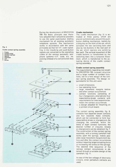
Fig. 6<br />
Cradle contact spring assembly<br />
1. Frame<br />
2. Contact strip<br />
3. Contact springs<br />
4. Spacer<br />
5. Camshaft<br />
6. Lid<br />
7. Screw<br />
During the development of ERICOFON<br />
700 the basic principle was therefore<br />
adopted that it should be possible<br />
to use the same push-button dialling<br />
mechanism for all existing automatic<br />
<strong>telephone</strong> systems. The mechanism<br />
works in accordance with the same<br />
principles as that for V.F. code signalling.<br />
In the impulsing unit push-button<br />
signals are converted to the signalling<br />
codes of the various automatic <strong>telephone</strong><br />
systems—V.F. code, d.c. impulsing<br />
(instead of a conventional dial)<br />
etc.<br />
Cradle mechanism<br />
The cradle mechanism (fig. 5) is activated<br />
at three points, which are<br />
placed symmetrically around the pushbutton<br />
dialling mechanism, namely by<br />
a long key on the front of the <strong>set</strong>, which<br />
activates the two switching bars and<br />
also by two buttons in the rear part of<br />
the <strong>set</strong>, which operate one switching<br />
bar each. The vertical movement of the<br />
cradle buttons is transformed by the<br />
switching bars into a torsional movement,<br />
which is transferred to the actuating<br />
device of the cradle contact<br />
spring assembly.<br />
Cradle contact spring assembly<br />
The requirements regarding low weight<br />
for ERICOFON 700, compact structure<br />
and a large number of contact functions,<br />
led to a new design of the contact<br />
spring assembly. The design requirements<br />
for this unit were:<br />
— small dimensions<br />
— low operating force<br />
—• large movement margins before<br />
and after contact occurrences<br />
— contact functions consisting of<br />
four changeovers, alternatively four<br />
make-before-break contacts with<br />
requirements for time sequence between<br />
the contact occurrences<br />
— a design adapted for mounting on<br />
a printed circuit board.<br />
The contact spring assembly, fig. 6,<br />
contains four separate break contacts<br />
and four separate make contacts,<br />
which can be connected to form four<br />
make-before-break or changeovers. By<br />
changing the camshaft, within the<br />
limits of eight contact functions, the<br />
desired number of closures, breaks<br />
or changeovers can be obtained, fig. 7.<br />
The construction of the contact spring<br />
assembly, with a turning camshaft that<br />
works upon the springs, makes possible<br />
large movement margins both before<br />
and after the contact occurrences<br />
without requiring largeractuating force<br />
or increasing the stress on the springs.<br />
The desired time sequence of the<br />
various contact occurrences is obtained<br />
through a suitable design of the<br />
camshaft, fig. 11.<br />
In view of the low voltage of <strong>electronic</strong><br />
circuits, silver palladium contacts are<br />
used.


