

DISCAERATOR - Operator Manual - McConnel
DISCAERATOR - Operator Manual - McConnel
DISCAERATOR - Operator Manual - McConnel

You also want an ePaper? Increase the reach of your titles
YUMPU automatically turns print PDFs into web optimized ePapers that Google loves.
Publication 588<br />
March 2009<br />
Part No. 41571.88<br />
Revision 29.06.11<br />
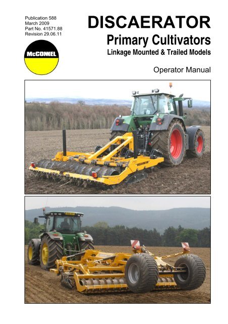
<strong>DISCAERATOR</strong><br />
Primary Cultivators<br />
Linkage Mounted & Trailed Models<br />
<strong>Operator</strong> <strong>Manual</strong>
IMPORTANT<br />
VERIFICATION OF WARRANTY REGISTRATION<br />
DEALER WARRANTY INFORMATION & REGISTRATION VERIFICATION<br />
It is imperative that the selling dealer registers this machine with <strong>McConnel</strong> Limited before<br />
delivery to the end user – failure to do so may affect the validity of the machine warranty.<br />
To register machines go to the <strong>McConnel</strong> Limited web site at www.mcconnel.com, log<br />
onto ‘Dealer Inside’ and select the ‘Machine Registration button’ which can be found in<br />
the Service Section of the site. Confirm to the customer that the machine has been<br />
registered in the section below.<br />
Should you experience any problems registering a machine in this manner please contact<br />
the <strong>McConnel</strong> Service Department on 01584 875848.<br />
Registration Verification<br />
Dealer Name: ……………………..…………………………………………………………….<br />
Dealer Address: …….………………………………………………………………………….<br />
Customer Name: ……………………..…………………………………………………………<br />
Date of Warranty Registration: ……/……/...…… Dealer Signature: ………………..……<br />
NOTE TO CUSTOMER / OWNER<br />
Please ensure that the above section above has been completed and signed by the selling<br />
dealer to verify that your machine has been registered with <strong>McConnel</strong> Limited.<br />
IMPORTANT: During the initial ‘bedding in’ period of a new machine it is the customer’s responsibility<br />
to regularly inspect all nuts, bolts and hose connections for tightness and re-tighten if required. New<br />
hydraulic connections occasionally weep small amounts of oil as the seals and joints settle in – where<br />
this occurs it can be cured by re-tightening the connection – refer to torque settings chart below. The<br />
tasks stated above should be performed on an hourly basis during the first day of work and at least<br />
daily thereafter as part of the machines general maintenance procedure.<br />
TORQUE SETTINGS FOR HYDRAULIC FITTINGS<br />
HYDRAULIC HOSE ENDS<br />
PORT ADAPTORS WITH BONDED SEALS<br />
BSP Setting Metric BSP Setting Metric<br />
1/4” 18 Nm 19 mm 1/4” 34 Nm 19 mm<br />
3/8” 31 Nm 22 mm 3/8” 47 Nm 22 mm<br />
1/2” 49 Nm 27 mm 1/2” 102 Nm 27 mm<br />
5/8” 60 Nm 30 mm 5/8” 122 Nm 30 mm<br />
3/4” 80 Nm 32 mm 3/4” 149 Nm 32 mm<br />
1” 125 Nm 41 mm 1” 203 Nm 41 mm<br />
1.1/4” 190 Nm 50 mm 1.1/4” 305 Nm 50 mm<br />
1.1/2” 250 Nm 55 mm 1.1/2” 305 Nm 55 mm<br />
2” 420 Nm 70 mm 2” 400 Nm 70 mm
WARRANTY POLICY<br />
WARRANTY REGISTRATION<br />
All machines must be registered, by the selling dealer with <strong>McConnel</strong> Ltd, before delivery to the end<br />
user. On receipt of the goods it is the buyer’s responsibility to check that the Verification of Warranty<br />
Registration in the <strong>Operator</strong>’s <strong>Manual</strong> has been completed by the selling dealer.<br />
1. LIMITED WARRANTIES<br />
1.01. All machines supplied by <strong>McConnel</strong> Limited are warranted to be free from defects in material<br />
and workmanship from the date of sale to the original purchaser for a period of 12 months,<br />
unless a different period is specified.<br />
1.02. All spare parts supplied by <strong>McConnel</strong> Limited are warranted to be free from defects in material<br />
and workmanship from the date of sale to the original purchaser for a period of 6 months.<br />
1.03. The manufacturer will replace or repair for the purchaser any part or parts found, upon<br />
examination at its factory, to be defective under normal use and service due to defects in<br />
material or workmanship. Returned parts must be complete and unexamined.<br />
1.04. This warranty does not apply to any part of the goods, which has been subjected to improper or<br />
abnormal use, negligence, alteration, modification, fitment of non-genuine parts, accident<br />
damage, or damage resulting from contact with overhead power lines, damage caused by<br />
foreign objects (e.g. stones, iron, material other than vegetation), failure due to lack of<br />
maintenance, use of incorrect oil or lubricants, contamination of the oil, or which has served its<br />
normal life. This warranty does not apply to any expendable items such as blades, flails, flap<br />
kits, skids, soil engaging parts, shields, guards, wear pads or pneumatic tyres.<br />
1.05. Temporary repairs and consequential loss - i.e. oil, downtime and associated parts are<br />
specifically excluded from the warranty.<br />
1.06. Warranty on hoses is limited to 12 months and does not include hoses which have suffered<br />
external damage. Only complete hoses may be returned under warranty, any which have been<br />
cut or repaired will be rejected.<br />
1.07. Machines must be repaired immediately a problem arises. Continued use of the machine after a<br />
problem has occurred can result in further component failures, for which <strong>McConnel</strong> Ltd cannot<br />
be held liable, and may have safety implications.<br />
1.08. Except as provided herein, no employee, agent, dealer or other person is authorised to give any<br />
warranties of any nature on behalf of <strong>McConnel</strong> Ltd.<br />
1.09. For machine warranty periods in excess of 12 months the following additional exclusions shall<br />
apply:<br />
1) Hoses, external seals, exposed pipes and hydraulic tank breathers.<br />
2) Filters.<br />
3) Rubber mountings.<br />
4) External electric wiring.<br />
1.10. All service work, particularly filter changes, must be carried out in accordance with the<br />
manufacturer’s service schedule. Failure to comply will invalidate the warranty. In the event of a<br />
claim, proof of the service work being carried out may be required.<br />
NB Warranty cover will be invalid if any non-genuine parts have been fitted or used. Use of<br />
non-genuine parts may seriously affect the machine’s performance and safety. <strong>McConnel</strong> Ltd<br />
cannot be held responsible for any failures or safety implications that arise due to the use of<br />
non-genuine parts.
2. REMEDIES AND PROCEDURES<br />
2.01. The warranty is not effective unless the Selling Dealer registers the machine, via the <strong>McConnel</strong><br />
web site and confirms the registration to the purchaser by completing the confirmation form in<br />
the operator’s manual.<br />
2.02. Any fault must be reported to an authorised <strong>McConnel</strong> dealer as soon as it occurs. Continued<br />
use of a machine, after a fault has occurred, can result in further component failure for which<br />
<strong>McConnel</strong> Ltd cannot be held liable.<br />
2.03. Repairs should be undertaken within two days of the failure. Claims submitted for repairs<br />
undertaken more than 2 weeks after a failure has occurred, or 2 days after the parts were<br />
supplied will be rejected, unless the delay has been authorised by <strong>McConnel</strong> Ltd.<br />
2.04. All claims must be submitted, by an authorised <strong>McConnel</strong> Service Dealer, within 30 days of the<br />
date of repair.<br />
2.05. Following examination of the claim and parts the manufacture will pay, at their discretion, for<br />
any valid claim the cost of any parts and an appropriate labour allowance if applicable.<br />
2.06. The submission of a claim is not a guarantee of payment.<br />
2.07. Any decision reached by <strong>McConnel</strong> Ltd. is final.<br />
3. LIMITATION OF LIABILITY<br />
3.01. The manufacturer disclaims any express (except as set forth herein) and implied warranties<br />
with respect to the goods including, but not limited to, merchantability and fitness for a particular<br />
purpose.<br />
3.02. The manufacturer makes no warranty as to the design, capability, capacity or suitability for use<br />
of the goods.<br />
3.03. Except as provided herein, the manufacturer shall have no liability or responsibility to the<br />
purchaser or any other person or entity with respect to any liability, loss, or damage caused or<br />
alleged to be caused directly or indirectly by the goods including, but not limited to, any indirect,<br />
special, consequential, or incidental damages resulting from the use or operation of the goods<br />
or any breach of this warranty. Notwithstanding the above limitations and warranties, the<br />
manufacturer’s liability hereunder for damages incurred by the purchaser or others shall not<br />
exceed the price of the goods.<br />
3.04. No action arising out of any claimed breach of this warranty or transactions under this warranty<br />
may be brought more than one (1) year after the cause of the action has occurred.<br />
4. MISCELLANEOUS<br />
4.01. The manufacturer may waive compliance with any of the terms of this limited warranty, but no<br />
waiver of any terms shall be deemed to be a waiver of any other term.<br />
4.02. If any provision of this limited warranty shall violate any applicable law and is held to be<br />
unenforceable, then the invalidity of such provision shall not invalidate any other provisions<br />
herein.<br />
4.03. Applicable law may provide rights and benefits to the purchaser in addition to those provided<br />
herein.
DECLARATION OF CONFORMITY<br />
Conforming to EU Machinery Directive 2006/42/EC<br />
We,<br />
McCONNEL LIMITED, Temeside Works, Ludlow, Shropshire SY8 1JL, UK<br />
Hereby declare that:<br />
The Product; Tractor Mounted / Trailed Primary Cultivator<br />
Product Code; SH32<br />
Serial No. & Date ………………………………… Type …………………………<br />
Manufactured in; United Kingdom<br />
Complies with the required provisions of the Machinery Directive 2006/42/EC<br />
The machinery directive is supported by the following harmonized standards;<br />
BS EN ISO 14121-1 (2007) Safety of machinery - Risk assessment, Part 1:<br />
Principles Part 2: practical guide and examples of methods.<br />
BS EN ISO 12100-1 (2010) Safety of machinery - Part 1: Basic terminology and<br />
methodology Part 2: Technical principles.<br />
BS EN 349(1993)+ A1 (2008) Safety of machinery - Minimum distances to avoid the<br />
entrapment with human body parts.<br />
BS EN 953 (1998) Safety of machinery - Guards General requirements for the<br />
design and construction of fixed and movable guards.<br />
BS EN 982(1996)+ A1 (2008) Safety requirements for fluid power systems and their<br />
components. Hydraulics<br />
McCONNEL LIMITED operates an ISO 9001:2008 quality management system,<br />
certificate number: FM25970.<br />
This system is continually assessed by the;<br />
British Standards Institution (BSI), Beech House, Milton Keynes, MK14 6ES, UK<br />
BSI is accredited by UK Accreditation Service, accreditation number: UKAS 003.<br />
The EC declaration only applies if the machine stated above is used in<br />
accordance with the operating instructions.<br />
Signed …………………................ Responsible Person<br />
on behalf of McCONNEL LIMITED<br />
Status: General Manager Date: May 2011
LIST OF CONTENTS<br />
General Information 2<br />
Features 3<br />
Introduction 4<br />
Specifications 5<br />
Component Location & Identification 6<br />
Safety Information 8<br />
Tractor Requirements 9<br />
Handling the Machine 10<br />
Attachment to Tractor 12<br />
Operation – Linkage Mounted Machines 13<br />
Operation – Trailed Machines 15<br />
Points, Legs & Discs 20<br />
Maintenance 30<br />
1
GENERAL INFORMATION<br />
Read this manual before fitting or operating the machine. Whenever any doubt exists<br />
contact your dealer or the <strong>McConnel</strong> Service Department for assistance.<br />
Use only ‘<strong>McConnel</strong> Genuine Parts’ on <strong>McConnel</strong> equipment and machinery<br />
DEFINITIONS - The following definitions apply throughout this manual:<br />
WARNING:<br />
An operating procedure, technique etc., which can result in personal injury or loss of life if<br />
not observed carefully.<br />
CAUTION:<br />
An operating procedure, technique etc., which can result in the damage of either machine<br />
or equipment if not observed carefully.<br />
NOTE:<br />
An operating procedure, technique etc., which is considered essential to emphasise.<br />
LEFT AND RIGHT HAND:<br />
This term is applicable to the machine when fitted to the tractor and viewed from the rear.<br />
This also applies to tractor references.<br />
Note: The illustrations in this manual are for instructional purposes only and may on occasion not<br />
show some components in their entirety. In some instances an illustration may appear slightly<br />
different to that of your particular model but the general procedure will be the same. E&OA.<br />
MACHINE & DEALER INFORMATION<br />
Record the Serial Number of your machine on this page and always quote this number when<br />
ordering parts. Whenever information concerning the machine is requested remember also to state<br />
the make and model of tractor to which the machine is fitted.<br />
Machine Serial Number:<br />
Machine Model details:<br />
Dealer Name:<br />
Dealer Address:<br />
Dealer Telephone No:<br />
Dealer Email Address:<br />
Installation Date:<br />
2
FEATURES<br />
Discaerator 3000<br />
3-point linkage mounted<br />
2.95M working width<br />
30” breakback protected legs<br />
Choice of mechanical or Auto-Reset breakback protection<br />
Height adjustable legs<br />
Choice of replaceable points<br />
Replaceable shins<br />
Choice of height adjustable rollers<br />
‘4 lives’ shear bars used on mechanical breakback models<br />
Rear lighting kit<br />
Discaerator 4000<br />
Trailed<br />
4.0M working widths<br />
Folding wings for transportation and storage<br />
30” breakback protected legs<br />
Choice of mechanical or Auto-Reset breakback protection<br />
Height adjustable legs<br />
Hydraulically adjustable leg frame<br />
Choice of replaceable points<br />
Replaceable shins<br />
Choice of height adjustable rollers<br />
‘4 lives’ shear bars used on mechanical breakback models<br />
Rear lighting kit<br />
3
INTRODUCTION<br />
<strong>McConnel</strong> Discaerators are primary cultivators designed specifically for one-pass seedbed<br />
preparation. The Discaerator 3000 model is a linkage mounted 3.0m machine and the<br />
4000 model is a tractor trailed machines with working width of 4.0m.<br />
The frames of the machines carry ‘breakback protected’ 30” legs each fitted with<br />
replaceable wear points that lift and loosen the soil beneath the surface while 2 rows of<br />
concave serrated discs set at opposing angles follow behind to chop, mix and cultivate the<br />
loosened surface. The process is finalised by a rear mounted, height adjusting roller(s)<br />
available in a variety of types. The ‘breakback protection system’ is available on all models<br />
in 2 specific options; mechanical or auto-reset.<br />
4
SPECIFICATIONS<br />
Discaerator 3000 Model<br />
Tractor Attachment<br />
3-point linkage (CAT.3)<br />
Tractor HP Requirement<br />
160+ (5 leg builds) / 180+ (7 leg builds)<br />
Number of Legs 5 or 7<br />
Leg Depth Adjustment<br />
35mm increments (Pin adjustment)<br />
Gas Strut Pre-charge<br />
100Bar<br />
Accumulator Pre-charge*<br />
50Bar (*Hydraulic leg models only)<br />
Accumulator By-pass Valve Pressure* 40Bar (*Hydraulic leg models only)<br />
Number of Discs 17<br />
Disc Diameter/Type<br />
508mm Concave & Serrated<br />
Disc Angle<br />
15° (opposed)<br />
Disc Configuration – First Row<br />
6 discs @ 500mm spacing<br />
Disc Configuration – Second Row<br />
11 discs @ 250mm spacing<br />
Working Width 2.95m<br />
Transport Width 3.0m<br />
Transport Height 1.65m<br />
Weight - 5 Leg c/w Ridge Packer Roller 2450Kg (Mechanical) / 2600Kg (Hydraulic)<br />
Weight - 7 Leg c/w Ridge Packer Roller 2700Kg (Mechanical) / 2850Kg (Hydraulic)<br />
Leg Shins<br />
Euroshins (replaceable)<br />
Points<br />
Longlife (replaceable) / Delta (replaceable)<br />
Roller Options:<br />
Standard Packer Roller<br />
Ø600mm<br />
Ridge Packer Roller<br />
Ø600mm<br />
Ridge Packer Roller (large)<br />
Ø800mm<br />
Guttler Roller<br />
Ø600mm<br />
Discaerator 4000 Model<br />
Tractor Attachment<br />
Trailed<br />
Tractor HP Requirement<br />
250+ (7 leg builds)<br />
Number of Legs 7 or 9<br />
Leg Depth Adjustment<br />
35mm increments (Pin adjustment)<br />
Gas Strut Pre-charge<br />
100Bar<br />
Number of Discs 26<br />
Disc Diameter/Type<br />
508mm Concave & Serrated<br />
Disc Angle<br />
15° (opposed)<br />
Disc Configuration – First Row<br />
9 discs @ 500mm spacing<br />
Disc Configuration – Second Row<br />
17 discs @ 250mm spacing<br />
Working Width 4.0m<br />
Transport Width 2.85m<br />
Transport Height -<br />
Weight - 9 Leg c/w Ridge Packer Roller<br />
6900Kg (Mechanical)<br />
Leg Shins<br />
Euroshins (replaceable)<br />
Points<br />
Longlife (replaceable) / Delta (replaceable)<br />
Roller Options:<br />
Standard Packer Roller -<br />
Ridge Packer Roller<br />
Ø600mm<br />
Ridge Packer Roller (large)<br />
Ø800mm<br />
Guttler Roller -<br />
5
COMPONENT LOCATION & IDENTIFICATION – Linkage Mounted Models<br />
McCONNEL <strong>DISCAERATOR</strong> 3000<br />
(Early auto-reset leg version illustrated)<br />
A) Mainframe<br />
B) Lower attachment positions<br />
C) Top link attachment position<br />
D) Parking/Stand legs<br />
E) Rear Roller<br />
F) Leg Assembly<br />
G) Shank<br />
H) Wear Shin<br />
I ) Point<br />
J) Breakaway Ram<br />
K) Accumulator (fitted to early builds only)<br />
L) Single Disc<br />
M) Double Disc<br />
N) Roller height adjustment points.<br />
O) Side Guard<br />
P) Literature Holder<br />
Q) Rear Lights<br />
6
COMPONENT LOCATION & IDENTIFICATION – Trailed Models<br />
McCONNEL <strong>DISCAERATOR</strong> 4000<br />
(Mechanical leg version illustrated)<br />
A) Centre Frame<br />
B) Folding Wings<br />
C) Tow Bar<br />
D) Rear Axle & Wheels<br />
E) Rear Roller<br />
F) Leg Assembly<br />
G) Shank<br />
H) Wear Shin<br />
I ) Point<br />
J) Single Disc<br />
K) Double Disc<br />
L) Side Guard<br />
M) Transport Locking Mechanism<br />
N) Wing Rams<br />
O) Depth Adjustment Rams<br />
P) Frame Height Rams<br />
Q) Ram Locks (Stops)<br />
R) Rear Lights<br />
S) Hose Stowage<br />
7
SAFETY SECTION<br />
This machine has the potential to be extremely dangerous, it is therefore imperative that<br />
both owner and operator of the machine reads and understands the following section to<br />
ensure they are fully aware of the dangers that do, or may exist, and their responsibilities<br />
surrounding the use and operation of the machine.<br />
When the machine is not in use it should be lowered to rest on the ground. In the event of<br />
any fault being detected with the machine’s operation it must be stopped immediately and<br />
not used again until the fault has been corrected by a qualified technician.<br />
▲ ALWAYS ensure all operators have read and understood the operation and safety<br />
information in the manual before using the machine.<br />
▲ ALWAYS inspect the work area for possible dangers or risk before starting work.<br />
▲ ALWAYS ensure all guards are in place and are kept in good condition – they are there<br />
for your protection and the safety of others.<br />
▲ ALWAYS keep clear of any moving or rotating components.<br />
▲ ALWAYS ensure that nuts holding the shanks to the machine frame are on the<br />
underside.<br />
▲ ALWAYS stop a working machine when other people enter a work area and only<br />
restart when the area is clear of any risk.<br />
▲ ALWAYS wear protective eye shields when striking points.<br />
▲ ALWAYS be alert – if any help is being given during the coupling or uncoupling of<br />
machines or any other equipment ensure the assistant is kept clear of risk of<br />
entrapment.<br />
▲ NEVER wear loose or flapping clothing near a working machine<br />
▲ NEVER permit anyone to ride on the machine, whether in transport or in work.<br />
▲ NEVER approach a working machine or attempt any kind of maintenance on a working<br />
machine.<br />
▲ NEVER work under a machine that is unsupported or raised on the tractors hydraulic<br />
lift – always use suitable substantial supports placed under the machine on a firm level<br />
work area.<br />
▲ NEVER allow bystanders near a working machine – ensure they remain at a safe<br />
distance from the machine.<br />
▲ NEVER permit children to play on a machine even when removed from the tractor and<br />
stored.<br />
8
TRACTOR REQUIREMENTS<br />
Tractor Power Requirements<br />
It is impossible to give any hard and fast figures on horsepower requirements as<br />
ground conditions can vary enormously. Figures quoted in the specification section are<br />
advisory only and may therefore vary depending on specific circumstances and<br />
conditions.<br />
Front End Weight<br />
It may be found to advantageous to apply front-end weight to some smaller and medium<br />
powered tractors. The amount of weight necessary can only be determined by local<br />
circumstances. It should be borne in mind with linkage mounted machines; any tendency<br />
of the tractor to rise on the front end will produce a corresponding lowering of hitch points,<br />
in doing so the angle of penetration of the shanks is further increased.<br />
Tractor Linkage – Linkage Mounted Models only<br />
It is essential that only the correct linkage arms for each particular tractor are used with the<br />
Discaerator. The arms have been properly matched with the horsepower of the tractor and<br />
should be more than ‘just’ adequate. There are no features on the Discaerator to offer<br />
protection against the failure of unmatched, repaired, badly worn, weak or below category<br />
tractor linkage.<br />
Failure of either of the tractor's draft links can cause the tractor to run away from one<br />
end of the implement or in the case of the top link, the implement to tip, risking damage<br />
to the machine and/or tractor.<br />
Under no circumstances should tractors operate in tandem in order to gain extra traction. It<br />
is far more practicable to make two or three passes over the ground with one tractor while<br />
increasing the depth on each pass.<br />
Stabilizers – Linkage Mounted Models only<br />
The implement must be capable of some side-to-side movement in relation to the tractor<br />
therefore stabilizer chains or sway bars must be adjusted to allow for this. They should<br />
however be tightened up to prevent side sway when travelling on the highway. In field<br />
operations stabilizer bars that hold the implement rigid should not be used.<br />
Draft Control – Linkage Mounted Models only<br />
Use of draft control is beneficial to traction in reducing wheel slip thereby also reducing<br />
tyre wear and saving fuel. Refer to individual tractors instruction book for detailed guidance<br />
on the best location for top link fitting.<br />
For mounting the cultivator on linkage behind crawler tractors, the draft links should be<br />
allowed to 'float' - provision for this is usually made in the hydraulic control valve.<br />
Do not use position control for regulation of depth. This should be done with the aid of<br />
the rear roller.<br />
9
HANDLING THE MACHINE – Linkage Mounted Machines<br />
WARNING!<br />
Read the information stated below before attempting to lift the machine using<br />
overhead lifting gear – failure to observe this advice may result in personal injury<br />
and/or damage to the machine.<br />
The machine should only be raised or lifted using suitable overhead lifting equipment with<br />
a minimum capacity of 3500kg SWL. It is recommended that 2 flat belt slings are used<br />
rather than chains which can cause surface damage to the machine. The lifting slings used<br />
should be 3 metres in length, capable of lifting minimum 3000kg and conform to BS 3481<br />
standard. Straps made from woven material should be inspected prior to use to ensure<br />
they are free from cuts, excessive wear or fraying. Protect slings from sharp-edged loads<br />
using sacking or similar padding.<br />
Lifting Points<br />
The slings should be looped under each of the two central box sections of the machine as<br />
shown below;<br />
LOOP SLINGS HERE<br />
It is vital that all lifts are performed<br />
vertically as any sideways pull tends<br />
to overload the edges of the belt with<br />
potential risk of either tearing them or<br />
moving them over possible rough<br />
edges that risk cutting them.<br />
WARNING:<br />
Ensure during the lifting procedures that the area is clear of obstacles and<br />
people and onlookers are kept at a safe distance from the machine at all times.<br />
10
HANDLING THE MACHINE – Trailed Machines<br />
WARNING!<br />
Read the information stated below before handling the machine – failure to<br />
observe this advice may result in personal injury and/or damage to the machine.<br />
As trailed models are axle and wheel mounted all major handling of the machine can be<br />
performed using a tractor or similar suitable vehicle. Always ensure the vehicle used is<br />
capable of towing the machines weight and that it is connected directly onto the tow hitch<br />
and not via chains or ropes.<br />
The lifting hooks on the top of the machine are primarily for use by the manufacturer<br />
during fabrication and assembly. These hooks may be used as a lifting point to raise one<br />
or other end of the unit if required but must never be used to lift the whole machine clear of<br />
the ground.<br />
Any form of raising the machine must only be performed on a firm level site using suitable<br />
equipment with a minimum lifting capability well in excess of the total weight being raised;<br />
wheels must be chocked front and rear before raising the machine and bystanders should<br />
be kept at a safe distance. Once raised the machine must be supported with blocks or<br />
suitable stands before attempting any maintenance or repairs. Never work under a raised<br />
machine that has not been safely and suitably supported.<br />
11
ATTACHMENT TO TRACTOR<br />
Attachment - Linkage Mounted Models<br />
Attachment of the machine should always be performed on a firm level site.<br />
Remove linkage pins from machines lower linkage points.<br />
Reverse the tractor squarely up to the machine until the tractor links align within the<br />
machines lower linkage points.<br />
Attach tractor links to lower linkage points with the pins supplied and secure with lock<br />
pins.<br />
Fit top link between tractor and machines upper linkage position using pins and lock<br />
pins.<br />
Raise the machine on the tractors linkage.<br />
Remove pins from parking legs, raise to highest position and refit pins.<br />
Adjust top link to bring the uprights of the frame into the vertical position.<br />
Fit and adjust check chains and/or stabiliser bars to centralize the machine on the<br />
tractor before locking tight in position for transport (*).<br />
(*) NOTE: For transport check chains and/or stabiliser bars must be tightened to prevent<br />
sideways sway of the machine during transportation. For work check chains and/or<br />
stabiliser bars should be slackened off to allow some degree of movement.<br />
Attachment - Trailed Models<br />
Attachment of the machine should always be performed on a firm level site.<br />
Reverse tractor squarely up to the front of the machine with the tow hitch inline and<br />
directly in front of the machines towing eye.<br />
Connect machine hoses to tractor’s external service points.<br />
Operate machine hydraulics to adjust tow bar to correct height for connection.<br />
Reverse tractor, connect hitch and secure.<br />
Operate height rams to raise frame to a height that gives suitable ground clearance for<br />
safe transportation.<br />
Swivel ‘stop tabs’ onto the ram rods of the height rams to support them at the desired<br />
height, and bring the rams down to rest on them.<br />
Connect rear lighting plug to tractor’s electrical output socket.<br />
The machine is now ready for transportation to the work site.<br />
NOTE: Where a trailed machine is used in conjunction with a crawler tractor equipped with<br />
a swinging drawbar, the drawbar should be used in the ‘locked’ mode for transport and set<br />
into swinging mode for working the machine; this will reduce sideways forces on the legs<br />
of the machine when manoeuvring in work.<br />
12
OPERATION – Linkage Mounted Machines<br />
Depth Adjustment & Regulation<br />
The overall working depth (Legs & Discs) is determined and regulated by the height at<br />
which the rear roller is set. A selection of holes in the roller bracket attachment point on<br />
each side the rear of the frame allows for a choice of height settings at which to set the<br />
roller. After selecting the desired height the ‘dog legged’ roller brackets are locked in<br />
position with the pins and lynch pins provided. Pin position ‘A’ indicated in the illustration<br />
below regulates the upper height and pin position ‘B’ the lower height. Ensure at all times<br />
that matching hole positions are selected on each side of the machine.<br />
Early model illustrated<br />
NOTE: It is advisable during transportation of the machine that the roller is ‘locked tight’ in<br />
position to avoid risk of the roller bouncing when travelling over rough terrain – this will<br />
reduce stress on components and increase stability of the carrying vehicle.<br />
13
Leg Depth Adjustment<br />
The working depth of each leg can be individually adjusted allowing them the ability to<br />
working higher or lower in relation to the discs and roller. By changing the height position<br />
of the shanks within the leg assembly the working depth can be adjusted in 35mm<br />
increments; this gives a variety of height adjustments. The shanks are held in position in<br />
the leg assemblies with pins and lynch pins.<br />
Depth Control<br />
To achieve maximum depth with a lower draft requirement it is possible where necessary<br />
to make more than one pass over the ground increasing the depth each time.<br />
Alternatively, some shanks can be removed.<br />
Calibration marks are cast into the sides of the shanks; centimetres on one side and<br />
inches on the other to assist the operator in maintaining more precise depth control.<br />
These are approximate calibrations and, obviously, will vary as the points wear.<br />
In setting the depth, it may be an advantage to set the rear roller high before pulling the<br />
points into the earth to the depth required, the roller can then be lowered to set and<br />
maintain the required depth.<br />
Machine Operation (Linkage Mounted Machines)<br />
Important note relating to early machines fitted with Hydraulic Accumulators; on initial<br />
installation, or after re-attachment to the tractor, the hose system from the tractor spool<br />
valve must be pressurized – details for performing this procedure are stated in the section<br />
entitled ‘Hydraulic Breakback System’.<br />
At the start of work the machine should be raised just clear of the ground, begin forward<br />
movement and lower the machine gradually into the earth on the tractors hydraulics whilst<br />
retaining forward momentum. When the roller settles on the surface the working depth has<br />
been reached and forward movement can continue at optimum speed for the job. On<br />
approaching the end of the pass the machine should be gradually raised on the tractor<br />
hydraulics so it is clear of the ground when the run is complete. Reduce speed and keep<br />
the machine raised for turning on the headland. Re-start the next pass as before.<br />
Speed<br />
When first putting the Discaerator into operation it is suggested that the tractor's forward<br />
speed be limited to less than 3mph (5kph). This can gradually be increased to find the<br />
optimum speed as experience with the machine is gained.<br />
14
OPERATION – Trailed Machines<br />
Moving into Work Position<br />
Moving the machine from transport to work position is performed by extending the wing<br />
rams to move the wings from the vertical transport position to the horizontal work position.<br />
For additional safety during transport the wings are secured in the vertical position by<br />
hydraulically operated latches, these latches automatically release on operation of the<br />
wing rams.<br />
WARNING! Ensure there is sufficient space around the machine before lowering<br />
the wings. Keep bystanders at a safe distance from the machine during all<br />
movements and operations.<br />
TRANSPORT POSITION<br />
A) Wing Rams<br />
B) Hydraulic Latch<br />
WORK POSITION<br />
Moving into Transport Position<br />
With leg frame raised to its highest position retract the wing rams (A) to move the machine<br />
from work position to transport position, safety latches (B) will automatically engage and<br />
lock to secure the wings when fully raised.<br />
15
Machine Height<br />
Operation of rams 1 & 2 adjust the height of the machines main frame, the rams are interconnected<br />
and work in tandem. NOTE: Ensure that ram stops are ‘swivelled’ off the rams<br />
before operation. Retracting the rams will lower the machine, extending the rams will raise<br />
the machine.<br />
Leg Working Depth - Hydraulic Height Adjustment of Legs<br />
For quick and easy adjustment of leg depth the parallel under-frame onto which the legs<br />
are mounted can be moved up or down hydraulically by operation of rams 3. Once the<br />
height has been set the rams must be locked by swivelling the ‘ram stops’ into position<br />
over the ram rods of each ram, ensure a matching number of stop tabs are used on each<br />
ram. The leg depth settings operate independent to the working depth of the discs.<br />
Leg Working Depth – Shank Adjustment<br />
Additional adjustments to the working<br />
depth of the legs can be made by<br />
manually changing the height position<br />
of the shanks within the leg assembly,<br />
the working depth can be adjusted in<br />
increments of 35mm giving a variety<br />
of height adjustments; the shanks are<br />
held in position in the leg assemblies<br />
with pins and lynch pins.<br />
(Auto-Reset type leg illustrated)<br />
16
Lowering Machine for Work<br />
The machine is lowered into work by retracting rams 1 & 2, when the tools contact the<br />
ground and resistance is sensed oil flow to ram 1 will be diverted to ram 2 which will then<br />
raise the rear axle and wheels clear of the ground.<br />
Disc Depth Adjustment<br />
Adjust the working depth of the discs by setting the height of the rear rollers; a selection of<br />
holes in the roller bracket attachment points, (indicated 4 below) allows for a choice of<br />
height settings at which to set the roller. After selecting the desired height the ‘dog legged’<br />
roller brackets are locked in position with the pins and lynch pins provided. Ensure that the<br />
hole positions selected for the roller height are identical both side to side and roller to<br />
roller. The holes are elongated to allow for a modicum of roller ‘float’.<br />
Setting of the roller height is best performed at the work site; draw the machine into the<br />
ground sufficient only to take the weight off the roller. Remove the height locking pins from<br />
each side of both roller arms before drawing the machine forward into the ground to the<br />
required working depth of the discs. Replace the roller height locking pins.<br />
17
Ram Stops<br />
Hydraulic rams on the machine that are subject to intense forces are equipped with ram<br />
stops; these can be positioned over the ram rod to physically ‘lock’ the cylinder at a<br />
specified point of extension, this not only strengthens the unit but also protects the ram<br />
and the hydraulic circuit. Early models use shaped steel tabs mounted adjacent to the ram<br />
which can be individually swivelled into position as required, whereas later models are<br />
supplied with a quantity of a ‘sprung clasp’ type.<br />
It is vital that ram stops are always fitted in position and the cylinders brought into contact<br />
with them on all relevant rams during machine operations and work. The required number<br />
of ram stops utilised can be varied depending on the particular work setup of the machine.<br />
For the hydraulically operated leg frame the same number of ram stops must be used on<br />
all 4 rams.<br />
Rams Stops on early models are mounted adjacent to the ram and swivel over the ram rod to ‘lock’ the cylinder.<br />
◄ Late models are supplied with ‘Sprung Clasp’ type Ram Stops.<br />
CAUTION!<br />
‘Ram Stops’ MUST be used to lock all applicable rams<br />
when working the machine – failure to observe this<br />
may result in damage to the machine.<br />
Variable Flow Control (Frame Lifting Rams)<br />
The hydraulic circuit for raising and lowering the<br />
machine incorporates variable flow valves linked to<br />
the front and rear rams; this allows the operator to<br />
adjust and fine tune the rate of oil flow to each of the<br />
rams to achieve parallel raising and lowering of the<br />
machine. Alternately, they can be adjusted and set to<br />
raise and lower the machine at an angle of the<br />
operators own preference.<br />
The valves, which feature an incremental scale, are<br />
adjusted by rotating the knob to either increase or<br />
reduce the flow rate to its particular ram, a grubscrew<br />
located in the knob can then be tightened to lock and<br />
secure it in position.<br />
Variable Flow Valve ►<br />
18
Machine Operation (Trailed Machines)<br />
Important note relating to early machines fitted with Hydraulic Accumulators; on initial<br />
installation, or after re-attachment to the tractor, the hose system from the tractor spool<br />
valve must be pressurized – details for performing this procedure are stated in the section<br />
entitled ‘Hydraulic Breakback System’.<br />
At the start of work the machine should be folded out into the work position and the<br />
required number of ‘ram stop tabs’ located onto the front frame lifting ram to hold the<br />
machine parallel when working in the ground – the number of tabs selected will vary<br />
depending on the particular setup of the individual machine.<br />
With the machine raised just clear of the ground, begin forward movement and gradually<br />
lower the machine into the earth whilst retaining forward momentum, the rear axle and<br />
wheels will automatically rise off the ground into their work position. When the roller settles<br />
on the surface the working depth has been reached and forward movement can continue<br />
at optimum speed for the job.<br />
On approaching the end of the pass gradually lift the machine out of work and up onto the<br />
wheels which will have automatically lowered into position thus allowing the machine to be<br />
turned.<br />
Reduce speed and keep the machine raised for turning on the headland. Re-start the next<br />
pass as before.<br />
CAUTION!<br />
Always raise the machine clear of the ground before attempting excessive turning<br />
or manoeuvres. Do not lower the machine into the ground whilst turning the unit.<br />
Speed<br />
When first putting the Discaerator into operation it is suggested that the tractor's forward<br />
speed be limited to less than 3mph (5kph). This can gradually be increased to find the<br />
optimum speed as experience with the machine is gained.<br />
19
Point Types<br />
Narrow points (Longlife Points)<br />
These are the normal choice for deep cultivation;<br />
the points will lift and shatter the soil structure with<br />
low draft and minimum mixing.<br />
Longlife Point<br />
Wide points (Delta Points)<br />
Wide points will break up a bigger area of ground<br />
and can therefore be spaced further apart;<br />
particularly useful for shallow cultivations.<br />
Delta Point<br />
Point Fitment<br />
The legs of the Discaerator use <strong>McConnel</strong> ‘slipper’ type points and are held in position with<br />
the wear shin. For fitment, the point is slid onto the shank and angled downwards to allow<br />
the toe of the wear shin to locate in the upper rear recess of the point – the shin may<br />
require ‘tapping’ into position to ensure a tight fit is achieved – the top of the shin is then<br />
secured on the shank with its fixing bracket, nut, and bolt.<br />
Breakback Protection Systems<br />
There are 2 types of breakback protection systems available for the Discaerator; these<br />
are Mechanical Breakback or Auto-Reset Breakback.<br />
NOTE: Early Auto-Reset machines utilised hydraulic accumulators and rams to provide<br />
breakback - from late 2010 onwards this system is superseded by self-contained gas<br />
struts.<br />
20
Mechanical Breakback System<br />
This system works on a shear bar method where a<br />
contact force with an object in excess of a<br />
measured limit will shear the locking bar of the leg<br />
allowing it freedom to pivot backwards and<br />
upwards, thus protecting major components from<br />
damage. Each shear bar has a total of 4 ‘lives’<br />
before a replacement will be required.<br />
The ‘4 Lives’ Shear Bar (Part No. 22520.54)<br />
NOTE: It is important when replacing shear bars that genuine <strong>McConnel</strong> replacements (Part No. 22520.54) are<br />
used as these are specially designed to shear under a pre-determined force. Use of non-genuine parts will<br />
risk expensive damage to the machine and/or tractor. Under no circumstances should the shear bolt be<br />
replaced by a bolt or a metal rod.<br />
Hydraulic Auto-Reset Breakback System (Early Machines)<br />
This system provides protection via hydraulic rams and<br />
accumulators; each leg is held in the work position by a<br />
hydraulic ram pressurized by pre-charged accumulators.<br />
When an object is struck producing a force in excess of a<br />
measured limit, the oil in the rams is forced back into the<br />
accumulators allowing the leg to breakback. Once the<br />
obstruction has been passed the accumulators will return the<br />
oil to re-pressurize the ram which then automatically returns<br />
the leg into the work position.<br />
DANGER! Keep clear of hydraulic legs when they are<br />
in the breakback position, residual pressure in the<br />
system may cause them to move without warning.<br />
Pressurising the Hose System<br />
The hose system from the tractor spool valve should be pressurised to 30-40BAR, an<br />
inline pressure gauge is fitted for both measuring and checking of the pressure. Pressurise<br />
the system by operation of the tractor spool valve until the correct pressure is reached, the<br />
spool valve must be set to<br />
minimum flow during this<br />
procedure to allow control of the<br />
flow rate into the system and<br />
also prevent the relief valve from<br />
being ‘overwhelmed’ with oil.<br />
Once the correct pressure is<br />
achieved the tractor spool valve<br />
should be returned to the<br />
neutral position.<br />
The pressure should always be<br />
checked prior to work and at<br />
regular intervals thereafter to<br />
ensure pressure remains within<br />
the specified limits.<br />
21
Shanks<br />
Shanks are made from extremely tough abrasive resistant steel and are subjected to a<br />
special heat treatment during manufacture. Do not attempt to hard face or otherwise weld<br />
the shank as this will destroy the shank’s properties. Owners are reminded that no<br />
warranty can be entertained on shanks that show evidence of welding.<br />
Shin guards, which can be supplied as an option, are made of special hard steel that will<br />
readily accept hard-face welding reinforcement.<br />
CAUTION! Do not attempt to hard face or otherwise weld the shanks - this will<br />
destroy the shank’s properties.<br />
Disc Working Depth<br />
The maximum working depth of the discs should not exceed 125mm (5”), working the<br />
discs at any depth greater than this will risk component damage. Always check the roller<br />
height is correctly set to ensure the discs cannot work at a depth in excess of this figure.<br />
22
Leg Positions – 3.0M Linkage Mounted Machines<br />
The legs of the machine are located on the front toolbars of the machine, the number of<br />
legs fitted will dictate their specific positions; the diagrams below show the positioning of<br />
the legs for each of the builds.<br />
5 Leg Builds<br />
7 Leg Builds<br />
23
Disc Positions – 3.0M Linkage Mounted Machines<br />
The machine uses 2 opposed rows of concave serrated discs which are located on the<br />
rear toolbars of the machine, the first row consists of 6 single discs positioned at 500mm<br />
spacing and the second row has 11 discs (5 double assemblies and 1 single) positioned at<br />
250mm spacing. The diagrams below show the dimensions required to correctly position<br />
the disc assemblies for correct spacing of the discs on specific machine builds.<br />
Machines WGC 1064900 to 1064919 inclusive<br />
Machines WGC 1064800 to 1064819 inclusive<br />
24
Leg Positions – 4.0M Trailed Machines<br />
7 Leg Builds<br />
9 Leg Builds<br />
25
Disc Positions – 4.0M Trailed Machines<br />
26
Working Depth<br />
The depth to which the Discaerator can best be used depends entirely on soil type and<br />
moisture content; the combination of these factors produces a critical depth, below this<br />
depth less soil is loosened and the tractor draught force is considerably greater. Down to<br />
the critical depth the breakout pattern is similar to figure 1. Below the critical depth figure<br />
2 applies. This can often be recognised from the surface but is very clearly seen by<br />
digging the profile.<br />
Figure 1 is the pattern produced by the narrow points and figure 3 is the pattern of the<br />
wide points – the wide points produce a much greater loosened area.<br />
Figure 4 shows the wide point working below the critical depth. This critical depth with<br />
the wide points may be lower than for the narrow points.<br />
The reason for this critical depth is that in for example figure 3 the soil has been<br />
loosened upwards because that is the direction of least resistance. In figure 4 the<br />
resistance to upwards movement is greater and it is easier for the soil to compact<br />
sideways than to loosen upwards. The very small amount of loosened soil at the top of<br />
the tine is because the loosening has been done by only the width of the shank. The<br />
sides of the compacted channel may be smeared and it is obvious that this is a very<br />
detrimental condition in which to leave the soil.<br />
27
Tine Spacing<br />
The tine spacing is related to the working depth for each type of point. With the narrow<br />
points the spacing should be 1.2 - 1.5 times the depth. This gives the least draught<br />
force and most even surface finish with complete break up of the soil profile (Fig.5).<br />
Figure 6 shows the same tines too far apart giving incomplete break up. With the wide<br />
points the spacing can be 2 - 2.2 times the working depth (Fig.7).<br />
Shallow Leading Tines<br />
Draught force can be reduced and the amount of soil loosened increased by using<br />
shallow tines in front of long ones. The 460mm shanks should be mounted to each side<br />
of the 610mm shank and not directly in front. Figure 8 shows an ideal setup.<br />
28
Re-compaction<br />
Loosened soil is extremely prone to re-compaction by subsequent traffic especially in wet<br />
conditions when loosening can be achieved by using wide points and shallow leading tines<br />
but any re-compaction will be more severe than the original problem. For this reason it is<br />
not a good idea to use two passes in different directions but to try to combine the two in<br />
one pass with for example shallow leading tines.<br />
If power is inadequate to cover the full width of the toolbar it is better to remove the<br />
shanks in the middle of the frame, which will leave an undisturbed strip of ground in the<br />
centre. On the return bout across the field the tractor wheels should be positioned on the<br />
unmoved strip to complete the cultivation on a straddle and overlap principle.<br />
29
MAINTENANCE<br />
Service and Maintenance<br />
Apart from regular lubrication of the roller assembly greasers, and ram greasers on<br />
models with hydraulic breakback legs, maintenance of the machine is limited to general<br />
cleaning and regular checking of the points and shin fixings for tightness.<br />
All lubrication points should be greased on a daily basis prior to work and before storage<br />
of the machine.<br />
Grease Daily<br />
Linkage Mounted Model illustrated<br />
Roller Grease Points (bracket pivot pin & end bearings)<br />
Hydraulic System (Hydraulic Breakback Models only)<br />
The hydraulic systems for both the 5 and 7 leg hydraulic breakback models comprise of<br />
single acting rams plumbed into three hose runs. The circuit is primed at the factory prior<br />
to delivery of the machine and will only require bleeding when hydraulic components are<br />
replaced.<br />
Bleeding the Hydraulic System<br />
Before attempting to bleed the system the oil safety note below should be read and the<br />
advice strictly adhered to.<br />
The 3 rams located at the ends of the hose runs are fitted with end caps, these will be the<br />
2 outer rams and the centre ram. With the supply hoses attached to the tractor, loosen the<br />
end caps of the 3 rams – do not loosen too much, ½ turn should be sufficient to allow the<br />
air to escape. Start the oil flow and observe the end caps, when oil begins to escape from<br />
the end caps, stop the flow and re-tighten the end caps.<br />
NOTE: Suitable containers should be used to catch any oil that escapes from the system –<br />
dispose of oil as advised by the manufacturer.<br />
Oil Safety<br />
Always wear suitable eye, hand and body protection when working with<br />
hydraulic oils – refer to the oil manufacturers’ safety information for further<br />
details and advice.<br />
Escaping oil under pressure is extremely dangerous – never check for leaks<br />
with your hand, use a piece of cardboard or similar material held at arms length.<br />
30
Accumulators<br />
Machines with hydraulic breakaway utilise tandem accumulators that are pre-charged with<br />
nitrogen when they leave the factory. Valves are located on the top of the accumulator<br />
cylinders for charging purposes only – do not open the valves or release the pressure;<br />
re-charging the accumulators requires the correct use of specialised equipment and must<br />
only be performed by the manufacturer or dealers qualified in this subject.<br />
Gas Struts<br />
Later version auto-reset machines are equipped with Nitrogen filled Gas Struts; these are<br />
factory pre-charged to 100Bar and will not require any intervention or maintenance by the<br />
operator. The filling valve located on the base of the strut must not be opened or interfered<br />
with under any circumstances – any adjustments or maintenance to this component must<br />
only be carried out by specialists or the manufacturer.<br />
31
<strong>McConnel</strong> Limited, Temeside Works, Ludlow, Shropshire SY8 1JL. England.<br />
Telephone: 01584 873131. Facsimile: 01584 876463. www.mcconnel.com


