Ascent 450 BL Park Glider PNP - E-flite
Ascent 450 BL Park Glider PNP - E-flite
Ascent 450 BL Park Glider PNP - E-flite

You also want an ePaper? Increase the reach of your titles
YUMPU automatically turns print PDFs into web optimized ePapers that Google loves.
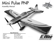
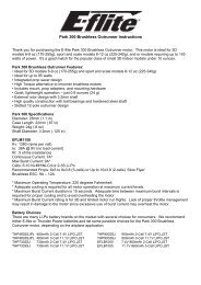
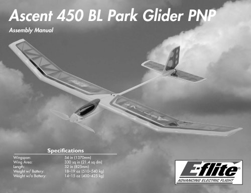
<strong>Ascent</strong> <strong>450</strong> <strong>BL</strong> <strong>Park</strong> <strong>Glider</strong> <strong>PNP</strong><br />
Assembly Manual<br />
Specifications<br />
Wingspan:<br />
54 in (1370mm)<br />
Wing Area:<br />
330 sq in (21.4 sq dm)<br />
Length:<br />
32 in (825mm)<br />
Weight w/ Battery:<br />
18–19 oz (510–540 kg)<br />
Weight w/o Battery: 14–15 oz (400–425 kg)
Table of Contents<br />
Specifications...................................................................... 1<br />
Introduction......................................................................... 2<br />
Using the Manual................................................................ 2<br />
Contents of Kit/Parts Layout................................................. 3<br />
Battery and Charger Selection.............................................. 3<br />
Covering Colors................................................................... 3<br />
Required Radio Equipment................................................... 3<br />
Required Tools and Adhesives............................................... 3<br />
Optional Accessories........................................................... 4<br />
Notes Regarding Servos and ESC......................................... 4<br />
Note on Lithium Polymer Batteries......................................... 4<br />
Warning............................................................................. 4<br />
Warranty Information........................................................... 4<br />
Safety, Precautions, and Warnings........................................ 6<br />
Wing Assembly................................................................... 7<br />
Stabilizer/Elevator Installation.............................................. 8<br />
Fin/Rudder Installation....................................................... 11<br />
Receiver Installation............................................................ 15<br />
Control Throws.................................................................. 17<br />
Center of Gravity............................................................... 17<br />
Range Test Your Radio........................................................ 18<br />
Instructions for Disposal of WEEE by<br />
Users in the European Union.................................... 18<br />
Preflight............................................................................. 18<br />
Glide Testing Your <strong>Ascent</strong> <strong>PNP</strong>............................................ 19<br />
Thermal Soaring................................................................ 20<br />
In-Flight Adjustments for Performance and Conditions.......... 23<br />
2008 Official AMA National Model Aircraft Safety Code.... 25<br />
Introduction<br />
Thank you for purchasing the <strong>Ascent</strong> <strong>450</strong> <strong>BL</strong> <strong>Park</strong> <strong>Glider</strong>.<br />
E-<strong>flite</strong>’s <strong>Ascent</strong> offers the modeler a <strong>PNP</strong> (Plug and Play) electric<br />
park glider that is pre-built to a high level of craftsmanship. It<br />
is unique in that it comes with the electric motor and folding<br />
propeller installed, complete with two sub micro servos<br />
and brushless 22 Amp ESC, saving a significant amount of<br />
construction time.<br />
The precovered and trimmed <strong>Ascent</strong> is a high-quality <strong>450</strong><br />
outrunner-powered park glider that can be flight ready in just<br />
a few evenings. The world of electric-powered park gliders<br />
is extremely challenging and rewarding. It is your skill and<br />
knowledge of the surrounding atmosphere, combined with the<br />
design capabilities of your model, that will result in your ability<br />
to defy the laws of gravity and produce flights of unbelievable<br />
distance and duration.<br />
With the electric motor, you can climb 300–500 feet (thermal<br />
hunting altitude) many times, resulting in flight times of up to<br />
an hour or more as you soar from thermal to thermal. We have<br />
included sections on "Thermal Soaring" and "Flight Trimming<br />
for Performance and Conditions" to help you achieve the most<br />
enjoyment from your <strong>Ascent</strong>. We believe you will have many<br />
enjoyable hours of challenging and rewarding flight. Happy<br />
thermal hunting!<br />
Using the Manual<br />
This manual is divided into sections to help make assembly<br />
easier to understand, and to provide breaks between each major<br />
section. In addition, check boxes have been placed next to each<br />
step to keep track of each step completed. Steps with a single<br />
circle () are performed once, while steps with two circles ( )<br />
indicate that the step will require repeating, such as for a right or<br />
left wing panel, two servos, etc.<br />
Remember to take your time and follow the directions.<br />
2 E-<strong>flite</strong> <strong>Ascent</strong> <strong>PNP</strong> Assembly Manual
Contents of Kit/Parts Layout<br />
Replacement Parts<br />
EFL2701 Wing Set<br />
EFL2702 Fuselage<br />
EFL2703 Tail Set<br />
EFL2704 Canopy<br />
EFL2705 Wing Tube<br />
Battery and Charger Selection<br />
EFLB12503S 1250mAh 3S 11.1V 20C LiPo, 13GA EC3<br />
EFLC3005 Celectra 1- to 3-cell Li-Po Charger<br />
EFLC505 1–5S Balancing Li-Po Charger<br />
Covering Colors<br />
HANU973 Lite White<br />
HANU954 Transparent Blue<br />
HANU964 Lite Clear<br />
HANU881 Silver<br />
Required Radio Equipment<br />
You will need a minimum 4-channel transmitter and micro<br />
receiver. We recommend the crystal-free, interference-free<br />
Spektrum DX6i 2.4GHz DSM ® 6-channel system, which includes<br />
a micro receiver.<br />
Complete Radio System<br />
SPM6600 DX6i DSM 6CH Radio System<br />
Or<br />
SPM6000<br />
Or<br />
SPM6100E<br />
AR6000 DSM 6-Channel <strong>Park</strong> Flyer Receiver<br />
(DX6, DX6i and DX7)<br />
AR6100E DSM2 Microlite 6-Channel Receiver,<br />
Air (DX6i and DX7 users only)<br />
Required Tools and Adhesives<br />
Tools & Equipment<br />
Ball driver: 3/32-inch<br />
Phillips screwdriver: #1<br />
Mixing sticks<br />
Ruler<br />
Hobby knife<br />
Rubbing alcohol<br />
Sandpaper<br />
Adhesives<br />
Medium CA<br />
6-Minute Epoxy (HAN8000)<br />
Felt-tipped pen<br />
Painter's tape<br />
Mixing cup<br />
Square<br />
#11 blades<br />
Paper towels<br />
Threadlock<br />
E-<strong>flite</strong> <strong>Ascent</strong> <strong>PNP</strong> Assembly Manual<br />
3
EFLA110<br />
Optional Accessories<br />
Power Meter<br />
Notes Regarding Servos and ESC<br />
WARNING: Use of servos other than those we recommend may<br />
overload the BEC of the recommended Electronic Speed Control<br />
(ESC). We suggest the use of only the servos we recommend<br />
when utilizing the recommended ESC’s BEC, or the use of a<br />
separate BEC (like the UBEC) or receiver battery pack when using<br />
other servos.<br />
Note on Lithium Polymer Batteries<br />
Lithium Polymer batteries are significantly more<br />
volatile than alkaline or Ni-Cd/Ni-MH batteries used<br />
in RC applications. All manufacturer’s instructions<br />
and warnings must be followed closely. Mishandling<br />
of Li-Po batteries can result in fire. Always follow the<br />
manufacturer’s instructions when disposing of Lithium<br />
Polymer batteries.<br />
Warning<br />
An RC aircraft is not a toy! If misused, it can cause serious bodily<br />
harm and damage to property. Fly only in open areas, preferably<br />
at AMA (Academy of Model Aeronautics) approved flying sites,<br />
following all instructions included with your radio.<br />
Keep loose items that can get entangled in the propeller away<br />
from the prop, including loose clothing, or other objects such as<br />
pencils and screwdrivers. Especially keep your hands away from<br />
the propeller.<br />
Warranty Period<br />
Warranty Information<br />
Horizon Hobby, Inc., (Horizon) warranties that the Products purchased<br />
(the “Product”) will be free from defects in materials and workmanship<br />
at the date of purchase by the Purchaser.<br />
Limited Warranty<br />
(a) This warranty is limited to the original Purchaser ("Purchaser") and<br />
is not transferable. REPAIR OR REPLACEMENT AS PROVIDED UNDER<br />
THIS WARRANTY IS THE EXCLUSIVE REMEDY OF THE PURCHASER.<br />
This warranty covers only those Products purchased from an<br />
authorized Horizon dealer. Third party transactions are not covered<br />
by this warranty. Proof of purchase is required for warranty claims.<br />
Further, Horizon reserves the right to change or modify this warranty<br />
without notice and disclaims all other warranties, express or implied.<br />
(b) Limitations- HORIZON MAKES NO WARRANTY OR<br />
REPRESENTATION, EXPRESS OR IMPLIED, ABOUT NON-<br />
INFRINGEMENT, MERCHANTABILITY OR FITNESS FOR A<br />
PARTICULAR PURPOSE OF THE PRODUCT. THE PURCHASER<br />
ACKNOWLEDGES THAT THEY ALONE HAVE DETERMINED THAT<br />
THE PRODUCT WILL SUITA<strong>BL</strong>Y MEET THE REQUIREMENTS OF THE<br />
PURCHASER’S INTENDED USE.<br />
(c) Purchaser Remedy- Horizon's sole obligation hereunder<br />
shall be that Horizon will, at its option, (i) repair or (ii) replace, any<br />
Product determined by Horizon to be defective. In the event of a<br />
defect, these are the Purchaser's exclusive remedies. Horizon reserves<br />
the right to inspect any and all equipment involved in a warranty<br />
claim. Repair or replacement decisions are at the sole discretion of<br />
Horizon. This warranty does not cover cosmetic damage or damage<br />
due to acts of God, accident, misuse, abuse, negligence, commercial<br />
use, or modification of or to any part of the Product. This warranty<br />
does not cover damage due to improper installation, operation,<br />
maintenance, or attempted repair by anyone other than Horizon.<br />
Return of any goods by Purchaser must be approved in writing by<br />
Horizon before shipment.<br />
4 E-<strong>flite</strong> <strong>Ascent</strong> <strong>PNP</strong> Assembly Manual
Damage Limits<br />
HORIZON SHALL NOT BE LIA<strong>BL</strong>E FOR SPECIAL, INDIRECT OR<br />
CONSEQUENTIAL DAMAGES, LOSS OF PROFITS OR PRODUCTION<br />
OR COMMERCIAL LOSS IN ANY WAY CONNECTED WITH THE<br />
PRODUCT, WHETHER SUCH CLAIM IS BASED IN CONTRACT,<br />
WARRANTY, NEGLIGENCE, OR STRICT LIABILITY. Further, in no<br />
event shall the liability of Horizon exceed the individual price of the<br />
Product on which liability is asserted. As Horizon has no control over<br />
use, setup, final assembly, modification or misuse, no liability shall be<br />
assumed nor accepted for any resulting damage or injury. By the act<br />
of use, setup or assembly, the user accepts all resulting liability.<br />
If you as the Purchaser or user are not prepared to accept the liability<br />
associated with the use of this Product, you are advised to return this<br />
Product immediately in new and unused condition to the place of<br />
purchase.<br />
Law: These Terms are governed by Illinois law (without regard to<br />
conflict of law principals).<br />
Safety Precautions<br />
This is a sophisticated hobby Product and not a toy. It must be<br />
operated with caution and common sense and requires some basic<br />
mechanical ability. Failure to operate this Product in a safe and<br />
responsible manner could result in injury or damage to the Product or<br />
other property. This Product is not intended for use by children without<br />
direct adult supervision. The Product manual contains instructions for<br />
safety, operation and maintenance. It is essential to read and follow<br />
all the instructions and warnings in the manual, prior to assembly,<br />
setup or use, in order to operate correctly and avoid damage or<br />
injury.<br />
Questions, Assistance, and Repairs<br />
Your local hobby store and/or place of purchase cannot provide<br />
warranty support or repair. Once assembly, setup or use of the<br />
Product has been started, you must contact Horizon directly. This will<br />
enable Horizon to better answer your questions and service you in the<br />
event that you may need any assistance. For questions or assistance,<br />
please direct your email to productsupport@horizonhobby.com, or call<br />
877.504.0233 toll free to speak to a service technician.<br />
Inspection or Repairs<br />
If this Product needs to be inspected or repaired, please call for a<br />
Return Merchandise Authorization (RMA). Pack the Product securely<br />
using a shipping carton. Please note that original boxes may be<br />
included, but are not designed to withstand the rigors of shipping<br />
without additional protection. Ship via a carrier that provides tracking<br />
and insurance for lost or damaged parcels, as Horizon is not<br />
responsible for merchandise until it arrives and is accepted<br />
at our facility. A Service Repair Request is available at www.<br />
horizonhobby.com on the “Support” tab. If you do not have internet<br />
access, please include a letter with your complete name, street<br />
address, email address and phone number where you can be reached<br />
during business days, your RMA number, a list of the included items,<br />
method of payment for any non-warranty expenses and a brief<br />
summary of the problem. Your original sales receipt must also be<br />
included for warranty consideration. Be sure your name, address, and<br />
RMA number are clearly written on the outside of the shipping carton.<br />
Warranty Inspection and Repairs<br />
To receive warranty service, you must include your original<br />
sales receipt verifying the proof-of-purchase date. Provided warranty<br />
conditions have been met, your Product will be repaired or replaced<br />
free of charge. Repair or replacement decisions are at the sole<br />
discretion of Horizon Hobby.<br />
E-<strong>flite</strong> <strong>Ascent</strong> <strong>PNP</strong> Assembly Manual<br />
5
Non-Warranty Repairs<br />
Should your repair not be covered by warranty the repair<br />
will be completed and payment will be required without<br />
notification or estimate of the expense unless the expense<br />
exceeds 50% of the retail purchase cost. By submitting the<br />
item for repair you are agreeing to payment of the repair without<br />
notification. Repair estimates are available upon request. You must<br />
include this request with your repair. Non-warranty repair estimates<br />
will be billed a minimum of ½ hour of labor. In addition you will be<br />
billed for return freight. Please advise us of your preferred method<br />
of payment. Horizon accepts money orders and cashiers checks, as<br />
well as Visa, MasterCard, American Express, and Discover cards.<br />
If you choose to pay by credit card, please include your credit card<br />
number and expiration date. Any repair left unpaid or unclaimed<br />
after 90 days will be considered abandoned and will be disposed of<br />
accordingly. Please note: non-warranty repair is only available<br />
on electronics and model engines.<br />
Electronics and engines requiring inspection or repair should be<br />
shipped to the following address:<br />
Horizon Service Center<br />
4105 Fieldstone Road<br />
Champaign, Illinois 61822<br />
All other Products requiring warranty inspection or repair should be<br />
shipped to the following address:<br />
Horizon Product Support<br />
4105 Fieldstone Road<br />
Champaign, Illinois 61822<br />
Please call 877-504-0233 with any questions or concerns<br />
regarding this product or warranty.<br />
Safety, Precautions, and Warnings<br />
As the user of this product, you are solely responsible for<br />
operating it in a manner that does not endanger yourself<br />
and others or result in damage to the product or the property<br />
of others.<br />
Carefully follow the directions and warnings for this and any<br />
optional support equipment (chargers, rechargeable battery<br />
packs, etc.) that you use.<br />
This model is controlled by a radio signal that is subject to<br />
interference from many sources outside your control. This<br />
interference can cause momentary loss of control so it is<br />
necessary to always keep a safe distance in all directions around<br />
your model, as this margin will help to avoid collisions or injury.<br />
• Always operate your model in an open area away from cars,<br />
traffic, or people.<br />
• Avoid operating your model in the street where injury or<br />
damage can occur.<br />
• Never operate the model out into the street or populated areas<br />
for any reason.<br />
• Never operate your model with low transmitter batteries.<br />
• Carefully follow the directions and warnings for this and any<br />
optional support equipment (chargers, rechargeable battery<br />
packs, etc.) that you use.<br />
• Keep all chemicals, small parts and anything electrical out of<br />
the reach of children.<br />
• Moisture causes damage to electronics. Avoid water exposure<br />
to all equipment not specifically designed and protected for<br />
this purpose.<br />
6 E-<strong>flite</strong> <strong>Ascent</strong> <strong>PNP</strong> Assembly Manual
Wing Assembly<br />
Required Parts<br />
Fuselage<br />
Wing panel (right and left)<br />
Aluminum wing tube #4 washer (2)<br />
4-40 x 1/2-inch socket head screw (2)<br />
Required Tools and Adhesives<br />
Ball driver: 3/32-inch<br />
<br />
1. Locate the aluminum wing tube and slide it into the<br />
hole in the wing root of one of the wing panels. The tube<br />
will slide in roughly half of its length.<br />
<br />
2. Slide the remaining wing panel onto the tube. The two<br />
wing panels will fit tightly together.<br />
<br />
3. Slide the dowels at the leading edge into the holes in<br />
the fuselage as shown.<br />
E-<strong>flite</strong> <strong>Ascent</strong> <strong>PNP</strong> Assembly Manual<br />
7
4. The wing will fit tight against the fuselage when<br />
installed.<br />
Stabilizer/Elevator Installation<br />
Required Parts<br />
Fuselage w/wing assembly<br />
Stabilizer<br />
Required Tools and Adhesives<br />
Ruler<br />
Felt-tipped pen<br />
Sandpaper<br />
Painter's tape<br />
6-minute epoxy<br />
Mixing stick<br />
Paper towel<br />
Mixing cup<br />
Rubbing alcohol<br />
Hobby knife w/new #11 blade<br />
<br />
1. Locate the horizontal stabilizer. Use a ruler to<br />
determine the center of the stabilizer. Use a felt-tipped<br />
pen to mark the center of the stabilizer.<br />
<br />
5. Use two 4-40 x 1/2-inch socket head screws and two<br />
#4 washers to secure the wing to the fuselage. Use a<br />
3/32-inch ball driver to tighten the screws.<br />
8 E-<strong>flite</strong> <strong>Ascent</strong> <strong>PNP</strong> Assembly Manual
2. Mark the center of the tail boom inside the boom using<br />
a felt-tipped pen.<br />
<br />
4. With the wing mounted to the fuselage, use a long<br />
ruler to measure the distance from the wing tip to the<br />
stabilizer tip as shown in the drawing. Carefully adjust<br />
the stabilizer until both measurements are equal.<br />
a<br />
a<br />
<br />
3. Use painter's tape to secure the stabilizer to<br />
the fuselage.<br />
E-<strong>flite</strong> <strong>Ascent</strong> <strong>PNP</strong> Assembly Manual<br />
9
5. Use a felt-tipped pen to transfer the outline of the<br />
fuselage onto the top of the stabilizer.<br />
Important: Use light pressure when cutting the covering<br />
to prevent cutting into the stabilizer. Cutting too deep will<br />
weaken the stabilizer and could cause it to fail in flight.<br />
<br />
7. Reposition the stabilizer and connect the bend from the<br />
elevator pushrod to the elevator control horn. The wire<br />
will enter the horn from the side closest to the fuselage.<br />
<br />
6. Remove the stabilizer from the fuselage. Use a hobby<br />
knife with a new #11 blade to remove the covering from<br />
inside the lines drawn in the previous step.<br />
10 E-<strong>flite</strong> <strong>Ascent</strong> <strong>PNP</strong> Assembly Manual
8. Step back and view the airframe from roughly 8-10<br />
feet (2-3 meters) to check the alignment of the stabilizer<br />
to the wing. If they are not parallel to each other, lightly<br />
sand the fuselage where the stabilizer mounts to correct<br />
the alignment.<br />
Required Parts<br />
Fuselage<br />
Skid<br />
Fin/Rudder Installation<br />
Required Tools and Adhesives<br />
Felt-tipped pen<br />
Painter's tape<br />
Mixing cup<br />
Hobby knife<br />
Sandpaper<br />
Paper towels<br />
<br />
Fin/rudder<br />
6-minute epoxy<br />
Square<br />
Mixing stick<br />
Medium CA<br />
Rubbing alcohol<br />
1. Check the fit of the fin to the fuselage. It should slide<br />
into the fuselage so the hinge line of the fin/rudder<br />
aligned with the hinge line from the stabilizer/elevator.<br />
<br />
9. Use 6-minute epoxy to glue the stabilizer to the<br />
fuselage. Use painter's tape to keep the stabilizer tight<br />
against the fuselage until the epoxy fully cures. You may<br />
use rubbing alcohol and paper towels to clean up any<br />
epoxy that has squeezed out during assembly.<br />
E-<strong>flite</strong> <strong>Ascent</strong> <strong>PNP</strong> Assembly Manual<br />
11
2. Use a felt-tipped pen to transfer the edge of the<br />
fuselage onto the bottom of the fin.<br />
<br />
4. Use sandpaper to remove the paint from the top of the<br />
fuselage. This is necessary to provide a bonding surface<br />
between the fin and fuselage.<br />
<br />
3. Use a felt-tipped pen to trace the outline of the fin on<br />
the top of the fuselage.<br />
Hint: Use tape to outline the area to sand to prevent<br />
removing paint from the surrounding area.<br />
12 E-<strong>flite</strong> <strong>Ascent</strong> <strong>PNP</strong> Assembly Manual
5. Use a hobby knife with a new #11 blade to remove<br />
the covering from the bottom of the fin.<br />
<br />
6. Reposition the fin and connect the rudder pushrod<br />
to the rudder control horn. The bend will enter the horn<br />
from the side of the horn closest to the stabilizer. You will<br />
need to put a small bend in the pushrod wire to connect<br />
it to the rudder.<br />
Important: Use light pressure when cutting the covering<br />
to prevent cutting into the fin. Cutting too deep will<br />
weaken the fin and could cause it to fail in flight.<br />
<br />
7. Use a square to check the alignment between the<br />
stabilizer and fin.<br />
E-<strong>flite</strong> <strong>Ascent</strong> <strong>PNP</strong> Assembly Manual<br />
13
8. Use 6-minute epoxy to glue the fin to the fuselage.<br />
<br />
10. Use a felt-tipped pen to trace the outline of the of the<br />
skid on the bottom of the stabilizer.<br />
<br />
9. Use painter's tape to keep the fin in position and<br />
square to the stabilizer while the epoxy cures. You may<br />
use rubbing alcohol and paper towels to clean up any<br />
squeeze out during this procedure.<br />
<br />
11. Use a hobby knife with a new #11 blade to<br />
remove the covering from inside the lines drawn in<br />
the previous step.<br />
14 E-<strong>flite</strong> <strong>Ascent</strong> <strong>PNP</strong> Assembly Manual
12. Use medium CA to glue the skid to the bottom of<br />
the stabilizer.<br />
Required Parts<br />
Receiver<br />
Motor battery<br />
Required Tools and Adhesives<br />
Phillips screwdriver: #1<br />
<br />
Receiver Installation<br />
Hook and loop tape<br />
Fuselage assembly<br />
1. Use a #1 Phillips screwdriver to remove the two screws<br />
that secure the canopy to the fuselage.<br />
E-<strong>flite</strong> <strong>Ascent</strong> <strong>PNP</strong> Assembly Manual<br />
15
2. Plug the elevator servo, rudder servo and speed<br />
control leads into the appropriate ports of the receiver.<br />
On a model that uses rudder and elevator control, it is<br />
common to plug the rudder servo into the aileron port.<br />
<br />
4. Install the motor battery inside the fuselage. Place<br />
the hook and loop tape on the battery and battery tray<br />
to keep the battery from moving forward or backward<br />
in the fuselage. The battery installation is completed by<br />
securing the battery with the hook and loop strap that is<br />
pre-installed in the fuselage.<br />
<br />
3. Use the supplied hook and loop tape to attach the<br />
receiver inside the fuselage.<br />
<br />
5. Turn on the radio and check the operation of the<br />
servos. Center the rudder stick and trim. After centering<br />
the rudder, use a #1 Phillips screwdriver to tighten<br />
the screw that secures the rudder pushrod wire. Once<br />
complete with the rudder, check the elevator centering as<br />
well.<br />
16 E-<strong>flite</strong> <strong>Ascent</strong> <strong>PNP</strong> Assembly Manual
Control Throws<br />
1. Turn on the transmitter and receiver of your <strong>Ascent</strong><br />
<strong>450</strong> <strong>BL</strong> <strong>Park</strong> <strong>Glider</strong> <strong>PNP</strong> ® . Check the movement of the<br />
rudder using the transmitter. When the stick is moved<br />
right, the rudder should also move right. Reverse the<br />
direction of the servo at the transmitter if necessary.<br />
2. Check the movement of the elevator with the radio<br />
system. Moving the elevator stick down will make the<br />
airplane elevator move up.<br />
3. Use a ruler to adjust the throw of the elevator and<br />
rudder. Adjust the position of the pushrod at the control<br />
horn to achieve the following measurements when<br />
moving the sticks to their endpoints.<br />
Note: Measurements are taken at the widest point<br />
on the surface.<br />
Elevator<br />
Center of Gravity<br />
An important part of preparing the aircraft for flight is properly<br />
balancing the model.<br />
Caution: Do not inadvertently skip this step!<br />
The recommended Center of Gravity (CG) location for<br />
the <strong>Ascent</strong> <strong>450</strong> <strong>BL</strong> <strong>Park</strong> <strong>Glider</strong> <strong>PNP</strong> is 1–1 1 /2-inch (25–38mm)<br />
back from the leading edge of the wing. Mark the location of the<br />
CG on the bottom of the wing.<br />
Please balance your model while it is upright with the<br />
battery installed. With the model upright, lift the model at<br />
the marks using your fingertips, or use a commercially available<br />
balancing stand. The model will rest level or slightly nose down<br />
when balanced correctly. Adjust the position of the motor battery,<br />
or add weight to the nose or tail if necessary to achieve the<br />
correct CG. Please understand that if you use a different Li-Po<br />
battery than the one included, you need to rebalance the model<br />
to verify the Center of Gravity.<br />
Low Rate: 5/8-inch (16mm) (Up/Down)<br />
High Rate: 1-inch (25mm) (Up/Down)<br />
Rudder<br />
1 1 /2-inch (38mm) (Right/Left)<br />
These are general guidelines measured from our own flight tests.<br />
You can experiment with higher rates to match your preferred<br />
style of flying.<br />
1<br />
1–1 / 2-inch<br />
(25–38mm)<br />
After the first flights, the CG position can be adjusted for your<br />
personal preference.<br />
E-<strong>flite</strong> <strong>Ascent</strong> <strong>PNP</strong> Assembly Manual<br />
17
Range Test Your Radio<br />
1. Please consult your radio instructions for complete<br />
range testing instructions.<br />
2. Double-check that all controls (aileron, elevator, rudder<br />
and throttle) move in the correct direction.<br />
3. Be sure that your transmitter batteries are fully<br />
charged, per the instructions included with your radio.<br />
Instructions for Disposal of WEEE by<br />
Users in the European Union<br />
This product must not be disposed of with other waste. Instead, it<br />
is the user’s responsibility to dispose of their waste equipment by<br />
handing it over to a designated collection point for the recycling<br />
of waste electrical and electronic equipment. The separate<br />
collection and recycling of your waste equipment at the time of<br />
disposal will help to conserve natural resources and ensure that<br />
it is recycled in a manner that protects human health and the<br />
environment. For more information about where you can drop<br />
off your waste equipment for recycling, please contact your local<br />
city office, your household waste disposal service or where you<br />
purchased the product.<br />
Check Your Radio<br />
Preflight<br />
Before going to the field, be sure that your batteries are fully<br />
charged per the instructions included with your radio. Charge<br />
both the transmitter and receiver pack for your airplane. Use the<br />
recommended charger supplied with your particular radio system,<br />
following the instructions provided with the radio. In most cases,<br />
the radio should be charged the night before going out flying.<br />
Before each flying session, be sure to range check your radio.<br />
See your radio manual for the recommended range and<br />
instructions for your radio system. Each radio manufacturer<br />
specifies different procedures for their radio systems. Next, start<br />
the motor. With the model securely anchored, check the range<br />
again. The range test should not be significantly affected. If it is,<br />
don’t attempt to fly! Have your radio equipment checked out by<br />
the manufacturer.<br />
Note: Keep loose items that can get entangled in<br />
the propeller away from the prop. These include<br />
loose clothing, or other objects such as pencils and<br />
screwdrivers. Especially keep your hands away from<br />
the propeller.<br />
Double-check that all controls (aileron, elevator, rudder and<br />
throttle) move in the correct direction.<br />
Check the radio installation and make sure all the control<br />
surfaces are moving correctly (i.e. the correct direction and with<br />
the recommended throws). Test run the motor and make sure<br />
it transitions smoothly from off to full throttle and back. Also<br />
ensure the engine is installed according to the manufacturer’s<br />
instructions, and it will operate consistently.<br />
Check all the control horns, servo horns, and clevises to make<br />
sure they are secure and in good condition. Replace any items<br />
that would be considered questionable. Failure of any of these<br />
components in flight would mean the loss of your aircraft.<br />
18 E-<strong>flite</strong> <strong>Ascent</strong> <strong>PNP</strong> Assembly Manual
Glide Testing Your <strong>Ascent</strong> <strong>PNP</strong><br />
We strongly recommend that before you fly your new <strong>Ascent</strong>,<br />
you first perform a test glide. Pick a flat spot that has soft, tall<br />
grass and is free from obstructions. You first want to check out the<br />
<strong>Ascent</strong>’s performance but also check your performance as a pilot.<br />
It also allows you to make corrections to any building or control<br />
defects that may have been overlooked. The test glide should be<br />
done with an assistant on a calm day.<br />
<br />
<br />
<br />
<br />
Hint: A good time during the day is very early in the<br />
morning or at dusk when the wind is calm. You want to<br />
be able to concentrate on what the model is doing, and<br />
have time to think about what you're doing. We will<br />
assume you have an assistant during the following steps.<br />
1. Range check your radio system and check the control<br />
throws. Make sure the control surfaces move in the<br />
proper direction.<br />
2. Have the assistant hold the <strong>Ascent</strong> under the wing<br />
near the CG and run forward until they can sense the<br />
wing developing lift. Don't release the glider yet. See if<br />
the model wants to lift. If not, add a bit of up elevator<br />
trim and try again.<br />
3. This step may take some practice on the part of your<br />
assistant. What you want them to do now is run forward,<br />
but a bit faster, with the nose of the plane pointed at the<br />
horizon with the wings level (not nose down or nose up).<br />
Then thrust the <strong>Ascent</strong> forward in a line straight toward<br />
the horizon and release it.<br />
4. When the assistant releases the model, watch it<br />
carefully. A properly trimmed aircraft will fly straight,<br />
gliding to a smooth landing about 50 feet away. If the<br />
<strong>Ascent</strong> pitches nose down, the CG is too far back and<br />
you have a nose-heavy condition. Remove some weight<br />
from the nose. If the <strong>Ascent</strong> pitches nose up sharply, and<br />
<br />
<br />
<br />
<br />
stalls, you have a tail-heavy condition (the CG is too far<br />
forward), and you need to remove weight from the tail or<br />
move the battery and receiver further forward.<br />
5. Turns to the left or right after launch can be adjusted<br />
through the use of right or left rudder trim.<br />
Important: Make any trim adjustments in small<br />
increments. Large changes can result in abrupt turns,<br />
causing tip stalls and loss of control.<br />
6. If you have to make large trim adjustments on your<br />
transmitter, you may have other problems, such as warps.<br />
Check the wings, elevator, and rudder to make sure there<br />
are no warps in the airframe. Make sure the wings are<br />
aligned and mounted properly on the fuselage. When<br />
you have the <strong>Ascent</strong> trimmed and the CG adjusted so<br />
it glides properly in a "hands off" manner, return your<br />
transmitter trim switches to their neutral position, then<br />
make the appropriate mechanical linkage corrections to<br />
return the control surfaces to their test glide positions.<br />
7. After you have made the necessary corrections, glide<br />
test the model again to make sure it is trimmed properly<br />
with the transmitter trims in neutral.<br />
8. You are now ready to launch under power. Hold the<br />
fuselage under the wing with the model powered up.<br />
Apply half throttle and gently toss the model into the<br />
wind at a slight nose up attitude. The model will fly out<br />
strongly and you will be able to climb to altitude in a<br />
very short time. Moving the throttle stick to idle (or cutoff)<br />
you will find the prop will stop spinning and fold against<br />
the fuselage. You are now ready to hunt for thermals and<br />
enjoy the calm air.<br />
E-<strong>flite</strong> <strong>Ascent</strong> <strong>PNP</strong> Assembly Manual<br />
19
Thermal Soaring<br />
A key component to soaring is the air mass the park glider flies<br />
in. Also, there is an energy source producing lift, either a warm<br />
air thermal (thermal lift), or the wind rising as it meets an obstacle<br />
such as a hill or a line of mountains (ridge lift). We will limit our<br />
discussion to describing thermal soaring.<br />
We will be using the electric motor to launch our park glider<br />
to altitude. Once at altitude we shut down the motor and the<br />
park glider will soar, eventually to return to earth until we use<br />
the motor to climb again. How then does a park glider stay<br />
aloft for long periods of time and travel long distances Some<br />
force has to provide sufficient lift to overcome gravity when the<br />
motor is not used.<br />
One such force is the thermal. The thermal is simply a column<br />
of rising warm air. Warm air is lighter (less dense) than cooler<br />
air and thus rises. The term "differential heating" is used to<br />
describe the generation of thermals. Descending cool air is<br />
known as "sink."<br />
Balloonists, to launch and fly their hot air balloons, use the<br />
principle of warm vs. cool air. They create and trap warm air<br />
inside the balloon envelope, and the warm air displaces the cool<br />
air, causing the balloon to inflate and rise until air begins to<br />
cool inside the envelope. The balloonist simply uses a propane<br />
heater to warm the air again, causing the balloon rises again or<br />
maintains its altitude.<br />
Nature generates thermals by the sun heating darker ground<br />
or objects more than lighter colored surfaces. The dark object<br />
absorbs the sun's heat becoming warm and thus warming the air<br />
above it.<br />
For a thermal to be formed, the sun (or a heat source such as a<br />
hot metal roof, factory, etc.) will heat the ground or surrounding<br />
air in one location faster or warmer than the surrounding air.<br />
The warm ground will warm the air above it and cause the air to<br />
begin to rise. Rising warm air can take on the form of a column<br />
or a funnel. Usually the part of the thermal near the ground is<br />
small and expands outward as it rises in altitude.<br />
Since the warming of air is usually a much smaller area than<br />
the total area, the thermal updraft will be faster than the cooler<br />
downdraft motion of air. This cooler downdraft of air is referred<br />
to as "sink" and causes glider flights to be of a much shorter<br />
duration as the lift generated by the wing is overcome by the<br />
downward motion of the air.<br />
To stay aloft one's task is to move from one thermal to another,<br />
utilizing the lift created by rising warm air. In level flight, a glider<br />
continuously descends in relation to the surrounding air. The only<br />
way to sustain flight in a glider beyond the sink time in still air<br />
(without a motor) is to fly in an air mass that is rising at a rate<br />
greater than the sink rate of the glider.<br />
Thermals usually cannot be seen. (An exception is a "dust<br />
devil—a small thermal that has picked up dust making it<br />
visible.) One can sometimes "feel" the presence of a thermal.<br />
A breath of air in an otherwise calm spot indicates the presence<br />
of a thermal. A shift in the wind (in a light breeze) probably<br />
indicates airflow into a thermal. And one can watch for the<br />
graceful soaring of birds, such as hawks and eagles to locate<br />
the presence of thermals.<br />
20 E-<strong>flite</strong> <strong>Ascent</strong> <strong>PNP</strong> Assembly Manual
Sometimes the wind will cause the thermal to bend or break,<br />
causing a warm air bubble that slowly travels downwind as it<br />
rises. Thermals can vary in strength, rising at speeds of a few<br />
hundred to over a thousand feet per minute.<br />
Thermal Form (Column)<br />
As you are flying your <strong>Ascent</strong>, watch it carefully. If you were in a<br />
full-size glider, you would be able to feel the "bump" of entering<br />
a thermal. Now you must depend on signs the glider gives as it<br />
approaches or enters a thermal.<br />
When the <strong>Ascent</strong> flies near a thermal that is rising, the wing<br />
closest to the thermal will also try to rise, causing the aircraft to<br />
"rock" slightly. The nearness of a thermal will cause the glider to<br />
"turn away" without any control input from the pilot.<br />
Executing a 270-degree turn<br />
There are several ways of entering a thermal. One is to continue<br />
the thermal-induced turn for 270 degrees. If the thermal is on<br />
your right, turn left for 270 degrees and enter at a right angle to<br />
the original flight path.<br />
Thermal Form (Bubble)<br />
E-<strong>flite</strong> <strong>Ascent</strong> <strong>PNP</strong> Assembly Manual<br />
21
Executing a 180-degree turn<br />
The second method is to make a wide 180-degree turn back<br />
into the thermal.<br />
Flying the Core of a Thermal<br />
Once in the thermal, you will need to try to stay in the center of<br />
the lift. Slow down by increasing the up elevator "trim" until the<br />
park glider is just above stall (minimum sink) speed. Make easy<br />
banking turns to find the area of highest lift (thermal core). When<br />
you have found the core of lift, tighten the turns to stay within the<br />
core of highest lift.<br />
As you gain experience, you will find it easier to locate thermals<br />
and track their progress.<br />
22 E-<strong>flite</strong> <strong>Ascent</strong> <strong>PNP</strong> Assembly Manual
• Pitch Attitude<br />
In-Flight Adjustments for<br />
Performance and Conditions<br />
• Minimum Sink Speed<br />
• Maximum Lift/Drag (L/D) Speed<br />
Pitch Attitude<br />
To determine the <strong>Ascent</strong>’s airspeed, you will have to watch<br />
carefully for its pitch attitude. Pitch attitude can best be described<br />
as the amount (degree) the nose of the aircraft is above or below<br />
a line relative to the horizon. The angle of attack term is used to<br />
describe the angle between the chord (width) of the wing and the<br />
direction the wing moves through the air.<br />
• Best Penetration Speed<br />
Once the fundamentals of launch, trim, and control of the <strong>Ascent</strong><br />
are learned, it's time to consider getting the most out of its ability<br />
to perform. To do that, you must learn how to trim your <strong>Ascent</strong> for<br />
maximum performance, whatever the current conditions are at the<br />
time. The key to trimming for maximum performance is to become<br />
knowledgeable of three key speeds: minimum sink, maximum lift/<br />
drag (L/D), and best penetration.<br />
These three speeds are what we call airspeeds, not ground<br />
speeds (the aircraft's speed across the ground). Thus the airspeed<br />
of the plane is relative to the air mass surrounding it.<br />
Longitudinal<br />
Axis<br />
Pitch<br />
Attitude<br />
Line Relative to Horizon<br />
Horizon<br />
Nose<br />
Center of<br />
Gravity<br />
E-<strong>flite</strong> <strong>Ascent</strong> <strong>PNP</strong> Assembly Manual<br />
23
Minimum Sink Speed<br />
In our discussion of thermals, we know sink is the cooler air<br />
moving downward to replace the warm air that is rising.<br />
Minimum sink speed is the speed at which a park glider loses<br />
altitude most slowly. As the term then implies, minimum sink<br />
speed gives the glider the maximum amount of time aloft from a<br />
given altitude. This is the speed to fly at when you are circling in<br />
thermals, or whenever you need the maximum lift the glider can<br />
produce. The pitch attitude will appear to be more nose-up.<br />
To determine what this speed is for your <strong>Ascent</strong>, fly it at a slow<br />
speed, slowing down until it just stalls, then trim it to fly at a<br />
speed just above where it begins to stall. Observe the pitch<br />
attitude at this speed. You will need to practice flying at this speed<br />
without stalling so you can come back to it whenever you want to<br />
when you are in a thermal or trying to maintain maximum lift.<br />
Maximum Lift/Drag (L/D) Speed<br />
This is the speed at which you can fly the maximum distance<br />
for a given altitude. It's used when you move from one thermal<br />
to another, or when you need to cover the maximum distance<br />
over ground. This will be a moderately faster airspeed than the<br />
minimum sink speed. You will have to experiment by starting from<br />
the minimum sink speed and add small amounts of down trim<br />
to increase speed slightly. This is the speed the <strong>Ascent</strong> performs<br />
the best for duration, and the speed at which you will do most<br />
of your flying. It will take practice until you are familiar with<br />
the <strong>Ascent</strong>'s attitude at this speed. Remember you will be flying<br />
slightly faster, at a lower pitch attitude as compared to minimum<br />
sink speed.<br />
Best Penetration Speed<br />
This is the speed at which the <strong>Ascent</strong> will travel forward against<br />
the wind or a thermal, as far and as quickly as possible. This<br />
speed will vary with the conditions, such as windy situations or<br />
very strong thermals. You will want to use this speed to escape<br />
from very strong lift (or sink). This speed has a more pronounced<br />
nose down appearance, which will vary with the conditions<br />
encountered. It will also not be a consistent attitude, but vary with<br />
the strength and direction of the lift/sink or wind.<br />
Once you have learned to launch and control your <strong>Ascent</strong> in a<br />
consistent manner, you will want to then proceed with practicing<br />
these three speeds. Remember these are trim speeds, so you<br />
will be using your trim lever to obtain them. For maximum<br />
performance, remember to use trim sparingly, don't depend on<br />
the stick, as you will only impart small movements that result in<br />
drag and battery drain.<br />
Practice Smooth Control Inputs and Use the Trim lever. (Remember<br />
you trimmed the <strong>Ascent</strong> in the first flights, and then set the<br />
mechanical linkages to reflect the trim imparted. You then set your<br />
trim levers back to neutral. Now you know why we performed<br />
that procedure, to allow you to use the trim lever for in-flight trim<br />
to better control flight performance.)<br />
There are other things that can be done to bring the performance<br />
level of your <strong>Ascent</strong> to its absolute best. However, they should<br />
not be attempted until you have become proficient in the launch,<br />
control, and trim of your model.<br />
The more you learn how to trim your <strong>Ascent</strong> for optimum<br />
performance, the more fun you can have chasing thermals!<br />
24 E-<strong>flite</strong> <strong>Ascent</strong> <strong>PNP</strong> Assembly Manual
2008 Official AMA National<br />
Model Aircraft Safety Code<br />
GENERAL<br />
1) I will not fly my model aircraft in sanctioned events, air shows<br />
or model flying demonstrations until it has been proven to be<br />
airworthy by having been previously, successfully flight tested.<br />
2) I will not fly my model higher than approximately 400 feet within 3<br />
miles of an airport without notifying the airport operator. I will give<br />
right-of-way and avoid flying in the proximity of full-scale aircraft.<br />
Where necessary, an observer shall be utilized to supervise flying<br />
to avoid having models fly in the proximity of full-scale aircraft.<br />
3) Where established, I will abide by the safety rules for the flying<br />
site I use, and I will not willfully or deliberately fly my models in a<br />
careless, reckless and/or dangerous manner.<br />
4) The maximum takeoff weight of a model is 55 pounds, except<br />
models flown under Experimental Aircraft rules.<br />
5) I will not fly my model unless it is identified with my name and<br />
address or AMA number on or in the model. (This does not apply<br />
to models while being flown indoors.)<br />
6) I will not operate models with metal-bladed propellers or with<br />
gaseous boosts, in which gases other than air enter their internal<br />
combustion engine(s); nor will I operate models with extremely<br />
hazardous fuels such as those containing tetranitromethane or<br />
hydrazine.<br />
RADIO CONTROL<br />
1) I will have completed a successful radio equipment ground range<br />
check before the first flight of a new or repaired model.<br />
2) I will not fly my model aircraft in the presence of spectators until I<br />
become a qualified flier, unless assisted by an experienced helper.<br />
3) At all flying sites a straight or curved line(s) must be established<br />
in front of which all flying takes place with the other side for<br />
spectators. Only personnel involved with flying the aircraft are<br />
allowed at or in front of the flight line. Intentional flying behind the<br />
flight line is prohibited.<br />
4) I will operate my model using only radio control frequencies<br />
currently allowed by the Federal Communications Commission.<br />
(Only properly licensed Amateurs are authorized to operate<br />
equipment on Amateur Band frequencies.)<br />
5) Flying sites separated by three miles or more are considered safe<br />
from site-to-site interference, even when both sites use the same<br />
frequencies. Any circumstances under three miles separation<br />
require a frequency management arrangement, which may be<br />
either an allocation of specific frequencies for each site or testing<br />
to determine that freedom from interference exists. Allocation plans<br />
or interference test reports shall be signed by the parties involved<br />
and provided to AMA Headquarters.<br />
Documents of agreement and reports may exist between (1) two<br />
or more AMA Chartered Clubs, (2) AMA clubs and individual<br />
AMA members not associated with AMA Clubs, or (3) two or<br />
more individual AMA members.<br />
6) For Combat, distance between combat engagement line<br />
and spectator line will be 500 feet per cubic inch of engine<br />
displacement. (Example: .40 engine = 200 feet.); electric motors<br />
will be based on equivalent combustion engine size. Additional<br />
safety requirements will be per the RC Combat section of the<br />
current Competition Regulations.<br />
7) At air shows or model flying demonstrations, a single straight line<br />
must be established, one side of which is for flying, with the other<br />
side for spectators.<br />
8) With the exception of events flown under AMA Competition rules,<br />
after launch, except for pilots or helpers being used, no powered<br />
model may be flown closer than 25 feet to any person.<br />
9) Under no circumstances may a pilot or other person touch a<br />
powered model in flight.<br />
E-<strong>flite</strong> <strong>Ascent</strong> <strong>PNP</strong> Assembly Manual<br />
25
26 E-<strong>flite</strong> <strong>Ascent</strong> <strong>PNP</strong> Assembly Manual
E-<strong>flite</strong> <strong>Ascent</strong> <strong>PNP</strong> Assembly Manual<br />
27
13398<br />
© 2008 Horizon Hobby, Inc.<br />
4105 Fieldstone Road<br />
Champaign, Illinois 61822<br />
(877) 504-0233<br />
horizonhobby.com<br />
E-<strong>flite</strong>RC.com