MANUAL rev 01 2005 eng LCA-D.pdf - Vetek Scales
MANUAL rev 01 2005 eng LCA-D.pdf - Vetek Scales
MANUAL rev 01 2005 eng LCA-D.pdf - Vetek Scales

Create successful ePaper yourself
Turn your PDF publications into a flip-book with our unique Google optimized e-Paper software.
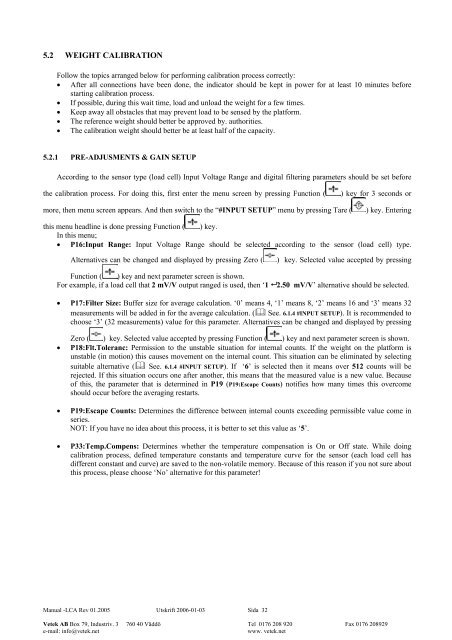
5.2 WEIGHT CALIBRATION<br />
Follow the topics arranged below for performing calibration process correctly:<br />
• After all connections have been done, the indicator should be kept in power for at least 10 minutes before<br />
starting calibration process.<br />
• If possible, during this wait time, load and unload the weight for a few times.<br />
• Keep away all obstacles that may p<strong>rev</strong>ent load to be sensed by the platform.<br />
• The reference weight should better be approved by. authorities.<br />
• The calibration weight should better be at least half of the capacity.<br />
5.2.1 PRE-ADJUSMENTS & GAIN SETUP<br />
According to the sensor type (load cell) Input Voltage Range and digital filtering parameters should be set before<br />
the calibration process. For doing this, first enter the menu screen by pressing Function (<br />
) key for 3 seconds or<br />
more, then menu screen appears. And then switch to the “#INPUT SETUP” menu by pressing Tare (<br />
) key. Entering<br />
this menu headline is done pressing Function ( ) key.<br />
In this menu;<br />
• P16:Input Range: Input Voltage Range should be selected according to the sensor (load cell) type.<br />
Alternatives can be changed and displayed by pressing Zero (<br />
) key. Selected value accepted by pressing<br />
Function ( ) key and next parameter screen is shown.<br />
For example, if a load cell that 2 mV/V output ranged is used, then ‘1 2.50 mV/V’ alternative should be selected.<br />
• P17:Filter Size: Buffer size for average calculation. ‘0’ means 4, ‘1’ means 8, ‘2’ means 16 and ‘3’ means 32<br />
measurements will be added in for the average calculation. ( See. 6.1.4 #INPUT SETUP). It is recommended to<br />
choose ‘3’ (32 measurements) value for this parameter. Alternatives can be changed and displayed by pressing<br />
Zero ( ) key. Selected value accepted by pressing Function ( ) key and next parameter screen is shown.<br />
• P18:Flt.Toleranc: Permission to the unstable situation for internal counts. If the weight on the platform is<br />
unstable (in motion) this causes movement on the internal count. This situation can be eliminated by selecting<br />
suitable alternative ( See. 6.1.4 #INPUT SETUP). If ‘6’ is selected then it means over 512 counts will be<br />
rejected. If this situation occurs one after another, this means that the measured value is a new value. Because<br />
of this, the parameter that is determined in P19 (P19:Escape Counts) notifies how many times this overcome<br />
should occur before the averaging restarts.<br />
• P19:Escape Counts: Determines the difference between internal counts exceeding permissible value come in<br />
series.<br />
NOT: If you have no idea about this process, it is better to set this value as ‘5’.<br />
• P33:Temp.Compens: Determines whether the temperature compensation is On or Off state. While doing<br />
calibration process, defined temperature constants and temperature curve for the sensor (each load cell has<br />
different constant and curve) are saved to the non-volatile memory. Because of this reason if you not sure about<br />
this process, please choose ‘No’ alternative for this parameter!<br />
Manual -<strong>LCA</strong> Rev <strong>01</strong>.<strong>2005</strong> Utskrift 2006-<strong>01</strong>-03 Sida 32<br />
<strong>Vetek</strong> AB Box 79, Industriv. 3 760 40 Väddö Tel <strong>01</strong>76 208 920 Fax <strong>01</strong>76 208929<br />
e-mail: info@vetek.net<br />
www. vetek.net