Download floresville-master-plan-draft.pdf - Wilson County News
Download floresville-master-plan-draft.pdf - Wilson County News
Download floresville-master-plan-draft.pdf - Wilson County News

Create successful ePaper yourself
Turn your PDF publications into a flip-book with our unique Google optimized e-Paper software.
CITY OF FLORESVILLE MASTER PLAN<br />
many of the <strong>plan</strong>ts constructed throughout the area at the time it was originally permitted and built. Its<br />
primary features are influent screening, an oxidation ditch, two clarifiers, a chlorine contact basin, and<br />
sludge dewatering equipment.<br />
Location and Discharge Point<br />
The existing wastewater treatment <strong>plan</strong>t is located on Goliad Road at the intersection with Standish St.<br />
The <strong>plan</strong>t discharges into the Lodi Branch of the San Antonio River adjacent to the <strong>plan</strong>t site and from<br />
there flows approximately two-thirds of a mile into the Segment 1911 of the San Antonio River Basin.<br />
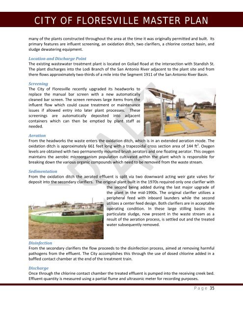
Screening<br />
The City of Floresville recently upgraded its headworks to<br />
replace the manual bar screen with a new automatically<br />
cleaned bar screen. The screen removes large items from the<br />
influent flow which could cause treatment or maintenance<br />
issues if allowed entry into later <strong>plan</strong>t processes. These<br />
screenings are automatically deposited into adjacent<br />
containers which can then be emptied by <strong>plan</strong>t staff as<br />
needed.<br />
Aeration<br />
From the headworks the waste enters the oxidation ditch, which is in an extended aeration mode. The<br />
oxidation ditch is approximately 661 feet long with a trapezoidal cross section area of 144 ft 2 . Oxygen<br />
levels are obtained with two permanently mounted brush aerators and one floating aerator. This oxygen<br />
maintains the aerobic microorganism population cultivated within the <strong>plan</strong>t which is responsible for<br />
breaking down the various organic compounds which need to be removed from the waste stream.<br />
Sedimentation<br />
From the oxidation ditch the aerated effluent is split via two downward acting weir gate valves for<br />
deposit into the secondary clarifiers. The original <strong>plan</strong>t built in the 1970s required only one clarifier with<br />
the second being added during the last major upgrade of<br />
the <strong>plan</strong>t in the mid-1990s. The original clarifier utilizes a<br />
peripheral feed with inboard launders while the second<br />
utilizes a center feed design. Both clarifiers are in acceptable<br />
operating condition. In these large stilling basins the<br />
particulate sludge, now present in the waste stream as a<br />
result of the aeration process, is settled out and the treated<br />
water subsequently removed.<br />
Disinfection<br />
From the secondary clarifiers the flow proceeds to the disinfection process, aimed at removing harmful<br />
pathogens from the effluent. The City accomplishes this through the use of dosed chlorine added in a<br />
baffled contact chamber at the end of the treatment train.<br />
Discharge<br />
Once through the chlorine contact chamber the treated effluent is pumped into the receiving creek bed.<br />
Effluent quantity is measured using a partial flume and ultrasonic meter for recording purposes.<br />
Page 35