ASSEMBLY INSTRUCTIONS
ASSEMBLY INSTRUCTIONS
ASSEMBLY INSTRUCTIONS

You also want an ePaper? Increase the reach of your titles
YUMPU automatically turns print PDFs into web optimized ePapers that Google loves.
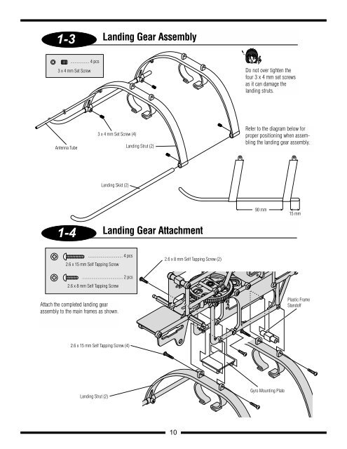
1-3<br />
Antenna Tube<br />
1-4<br />
.................. 4 pcs<br />
3 x 4 mm Set Screw<br />
3 x 4 mm Set Screw (4)<br />
Landing Skid (2)<br />
................................. 4 pcs<br />
2.6 x 15 mm Self Tapping Screw<br />
....................................... 2 pcs<br />
2.6 x 8 mm Self Tapping Screw<br />
Attach the completed landing gear<br />
assembly to the main frames as shown.<br />
2.6 x 15 mm Self Tapping Screw (4)<br />
Landing Strut (2)<br />
Landing Gear Assembly<br />
Landing Strut (2)<br />
Landing Gear Attachment<br />
2.6 x 8 mm Self Tapping Screw (2)<br />
10<br />
Do not over tighten the<br />
four 3 x 4 mm set screws<br />
as it can damage the<br />
landing struts.<br />
Refer to the diagram below for<br />
proper positioning when assembling<br />
the landing gear assembly.<br />
90 mm<br />
Gyro Mounting Plate<br />
15 mm<br />
Plastic Frame<br />
Standoff