ASSEMBLY INSTRUCTIONS
ASSEMBLY INSTRUCTIONS
ASSEMBLY INSTRUCTIONS

Create successful ePaper yourself
Turn your PDF publications into a flip-book with our unique Google optimized e-Paper software.
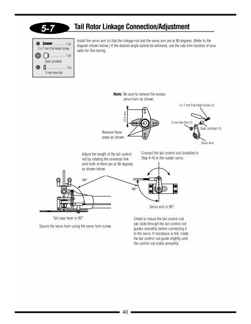
5-7<br />
............... 1 pc<br />
2 x 7 mm Flat Head Screw<br />
................... 1 pc<br />
Steel Jointball<br />
........................ 1 pc<br />
2 mm Hex Nut<br />
Tail case lever is 90°.<br />
Tail Rotor Linkage Connection/Adjustment<br />
Install the servo arm so that the linkage rod and the servo arm are at 90 degrees. (Refer to the<br />
diagram shown below.) If the desired angle cannot be achieved, use the sub-trim function of your<br />
radio for fine tuning.<br />
90°<br />
12.5 mm<br />
Adjust the length of the tail control<br />
rod by rotating the universal link<br />
until both of them are at 90 degrees<br />
as shown below.<br />
Secure the servo horn using the servo horn screw.<br />
Note: Be sure to remove the excess<br />
servo horn as shown.<br />
Remove these<br />
areas as shown.<br />
40<br />
90°<br />
Servo arm is 90°.<br />
2 x 7 mm Flat Head Screw (1)<br />
2 mm Hex Nut (1)<br />
Connect the tail control rod (installed in<br />
Step 4-4) to the rudder servo.<br />
Check to insure the tail control rod<br />
can slide through the tail control rod<br />
guides smoothly before connecting it<br />
to the servo. If resistance is felt, rotate<br />
the tail control rod guide slightly until<br />
the control rod slides smoothly.<br />
Steel Jointball (1)<br />
Servo Arm