ASSEMBLY INSTRUCTIONS
ASSEMBLY INSTRUCTIONS
ASSEMBLY INSTRUCTIONS

Create successful ePaper yourself
Turn your PDF publications into a flip-book with our unique Google optimized e-Paper software.
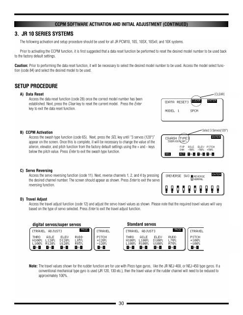
3. JR 10 SERIES SYSTEMS<br />
CCPM SOFTWARE ACTIVATION AND INITIAL ADJUSTMENT (CONTINUED)<br />
The following activation and setup procedure should be used for all JR PCM10, 10S, 10SX, 10SxII, and 10X systems.<br />
Prior to activating the CCPM function, it is first suggested that a data reset function be performed to reset the desired model number to be used back<br />
to the factory default settings.<br />
Caution: Prior to performing the data reset function, it will be necessary to select the desired model number to be used. Access the model select function<br />
(code 84) and select the desired model to be used.<br />
SETUP PROCEDURE<br />
A) Data Reset<br />
Access the data reset function (code 28) once the correct model number has been<br />
established. Next, press the Clear key to reset the current model. Press the Enter<br />
key to exit the data reset function.<br />
B) CCPM Activation<br />
Access the swash type function (code 65). Next, press the SEL key until “3 servos (120°)”<br />
appear on the screen. Once this is complete, it will be necessary to change the value of the<br />
aileron, elevator, and pitch function from the factory default settings using the + and - keys<br />
below the pitch value. Press Enter to exit the swash type function.<br />
C) Servo Reversing<br />
Access the servo reversing function (code 11). Next, reverse channels 1, 2, and 4 by pressing<br />
the desired channel number. The screen should appear as shown. Press Enter to exit the servo<br />
reversing function.<br />
D) Travel Adjust<br />
Access the travel adjust function (code 12) and adjust the servo travel values as shown. Please note that the required travel values will vary<br />
based on the type of servo selected. Press Enter to exit the travel adjust function.<br />
digital servos/super servos Standard servos<br />
[TRAVEL ADJUST]<br />
THRO<br />
H100%<br />
L100%<br />
AILE<br />
L120%<br />
R120%<br />
ELEV<br />
D120%<br />
U120%<br />
RUDD<br />
L85%<br />
R85%<br />
+ CL – + CL – + CL – + CL –<br />
PAGE<br />
Note: The travel values shown for the rudder function are for use with Piezo type gyros, like the JR NEJ-400, or NEJ-450 type gyros. If a<br />
conventional mechanical type gyro is used (JR 120, 130 etc.), then the travel value of the rudder channel will need to be reduced to<br />
approximately 100%.<br />
30<br />
[DATA RESET]<br />
[TRAVELADJUST] [TRAVEL ADJUST]<br />
PITCH<br />
+120%<br />
THRO<br />
H100%<br />
L100%<br />
AILE<br />
L100%<br />
R100%<br />
ELEV<br />
D100%<br />
U100%<br />
RUDD<br />
L70%<br />
R70%<br />
-120%<br />
+ CL – + CL –<br />
+ CL – + CL – + CL – + CL –<br />
MODEL 1 SPCM<br />
CLEAR ENTER<br />
[SWASH TYPE]<br />
3SERVOS(120•)<br />
FXP<br />
[NH<br />
AILE<br />
-50%<br />
ELEV<br />
-50%<br />
PITCH<br />
+50%<br />
SEL ACT + CL – + CL – + CL –<br />
[REVERSE SW] REVERSE<br />
NORMAL<br />
ENTER<br />
ENTER<br />
1 2 3 4 5 6 7 8 9 10<br />
PAGE<br />
[TRAVEL ADJUST]<br />
PITCH<br />
+100%<br />
[CLEAR]<br />
Select 3 Servos(120°)<br />
-100%<br />
+ CL – + CL – + CL –