ASSEMBLY INSTRUCTIONS
ASSEMBLY INSTRUCTIONS
ASSEMBLY INSTRUCTIONS

You also want an ePaper? Increase the reach of your titles
YUMPU automatically turns print PDFs into web optimized ePapers that Google loves.
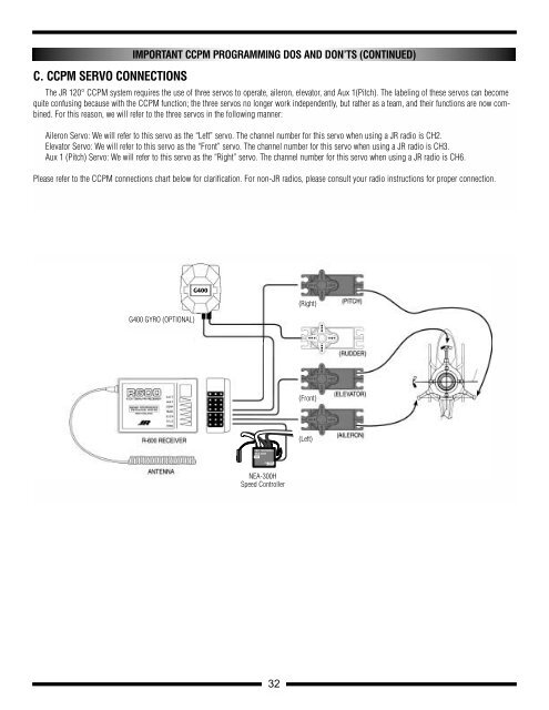
C. CCPM SERVO CONNECTIONS<br />
5-1<br />
IMPORTANT CCPM PROGRAMMING DOS AND DON’TS (CONTINUED)<br />
The JR 120° CCPM system requires the use of three servos to operate, aileron, elevator, and Aux 1(Pitch). The labeling of these servos can become<br />
quite confusing because with the CCPM function; the three servos no longer work independently, but rather as a team, and their functions are now combined.<br />
For this reason, we will refer to the three servos in the following manner:<br />
Aileron Servo: We will refer to this servo as the “Left” servo. The channel number for this servo when using a JR radio is CH2.<br />
Elevator Servo: We will refer to this servo as the “Front” servo. The channel number for this servo when using a JR radio is CH3.<br />
Aux 1 (Pitch) Servo: We will refer to this servo as the “Right” servo. The channel number for this servo when using a JR radio is CH6.<br />
Please refer to the CCPM connections chart below for clarification. For non-JR radios, please consult your radio instructions for proper connection.<br />
G400 GYRO (OPTIONAL)<br />
G400<br />
NEA-300H<br />
Speed Controller<br />
32<br />
(Right)<br />
(Front)<br />
(Left)