ASSEMBLY INSTRUCTIONS
ASSEMBLY INSTRUCTIONS
ASSEMBLY INSTRUCTIONS

Create successful ePaper yourself
Turn your PDF publications into a flip-book with our unique Google optimized e-Paper software.
6-5<br />
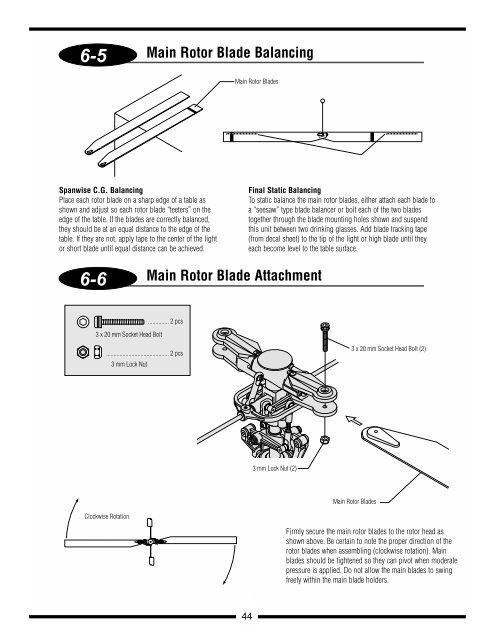
Spanwise C.G. Balancing<br />
Place each rotor blade on a sharp edge of a table as<br />
shown and adjust so each rotor blade “teeters” on the<br />
edge of the table. If the blades are correctly balanced,<br />
they should be at an equal distance to the edge of the<br />
table. If they are not, apply tape to the center of the light<br />
or short blade until equal distance can be achieved.<br />
6-6<br />
3 x 20 mm Socket Head Bolt<br />
3 mm Lock Nut<br />
.............. 2 pcs<br />
.......................................... 2 pcs<br />
Clockwise Rotation<br />
Main Rotor Blade Balancing<br />
Main Rotor Blades<br />
Main Rotor Blade Attachment<br />
Final Static Balancing<br />
To static balance the main rotor blades, either attach each blade to<br />
a “seesaw” type blade balancer or bolt each of the two blades<br />
together through the blade mounting holes shown and suspend<br />
this unit between two drinking glasses. Add blade tracking tape<br />
(from decal sheet) to the tip of the light or high blade until they<br />
each become level to the table surface.<br />
44<br />
3 mm Lock Nut (2)<br />
3 x 20 mm Socket Head Bolt (2)<br />
Main Rotor Blades<br />
Firmly secure the main rotor blades to the rotor head as<br />
shown above. Be certain to note the proper direction of the<br />
rotor blades when assembling (clockwise rotation). Main<br />
blades should be tightened so they can pivot when moderate<br />
pressure is applied. Do not allow the main blades to swing<br />
freely within the main blade holders.