


You also want an ePaper? Increase the reach of your titles
YUMPU automatically turns print PDFs into web optimized ePapers that Google loves.
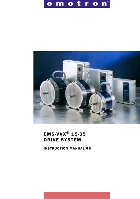
<strong>EMS</strong>-<strong>VVX</strong> ® <strong>15</strong>-<strong>35</strong><br />
DRIVE SYSTEM<br />
INSTRUCTION MANUAL <strong>GB</strong>
Valid for the following models:<br />
<strong>EMS</strong>-<strong>VVX</strong> <strong>15</strong>S<br />
<strong>EMS</strong>-<strong>VVX</strong> <strong>15</strong>E<br />
<strong>EMS</strong>-<strong>VVX</strong> 25S<br />
<strong>EMS</strong>-<strong>VVX</strong> 25E<br />
<strong>EMS</strong>-<strong>VVX</strong> <strong>35</strong>S<br />
<strong>EMS</strong>-<strong>VVX</strong> <strong>35</strong>E<br />
Software version R1<br />
The product is protected as follows:<br />
Patents: US 4 868 478; EP 0 285 637; SE 8604308-0;<br />
US 5 3<strong>15</strong> 224; EP 0 507 8<strong>35</strong>; SE 9002217-9;<br />
SE 9902821-9<br />
Registered design: DE 400 05 393.4.<br />
Registered designs pending:<br />
SE 992 196; US 29/124 164<br />
Document number: 01-2<strong>15</strong>7-01<br />
Edition: <strong>r2a</strong><br />
Date of publication: 18 November 2002<br />
© Copyright <strong>Emotron</strong> AB 2002<br />
<strong>Emotron</strong> AB reserves the right to change without warning<br />
specifications in the text and in illustrations. The contents of<br />
this document may not be copied without the permission of<br />
<strong>Emotron</strong> AB.<br />
2
SAFETY REGULATIONS<br />
During installation<br />
• Read the instruction manual completely before installation<br />
and commissioning.<br />
• The installation must be carried out by qualified personnel.<br />
• General conditions and regulations for the installation and<br />
operation of electrical machinery must be observed.<br />
• Measures to protect against personal injury and damage to the<br />
machine must be taken following local rules and regulations.<br />
• The drive system <strong>EMS</strong>-<strong>VVX</strong> is intended for permanent<br />
installation.<br />
• Cables may not be connected or disconnected while the supply<br />
voltage is on.<br />
• Check that the equipment is correctly connected before it is<br />
taken into use, see the instructions in the chapter on Mounting/Connection.<br />
• Faults that arise due to faulty installation or operation are not<br />
covered by the guarantee.<br />
During operation<br />
• Measurement in the control unit during operation may only<br />
take place at the connection terminal blocks. NOTE! Great<br />
care must be taken.<br />
• The units may not be opened or disassembled during operation.<br />
During disassembly and scrapping<br />
• The housing of the control unit is made from aluminium and<br />
steel. The material must be handled and recycled following<br />
the relevant laws.<br />
• The circuit board contains small amounts of tin and lead,<br />
which must be handled and recycled in accordance with the<br />
relevant laws.<br />
• The motor is made from copper, plastic, aluminium and iron.<br />
These materials must be handled and recycled in accordance<br />
with the relevant laws.<br />
3
CONTENTS<br />
1. DESCRIPTION......................................................... 5<br />
1.1 Introduction ................................................................... 5<br />
1.2 Product range .................................................................5<br />
1.3 Operating indicators / built-in functions............................6<br />
2. MOUNTING/CONNECTION..................................... 10<br />
2.1 Mounting ......................................................................10<br />
2.2 Connection....................................................................11<br />
3. MAINTENANCE/TROUBLESHOOTING..................... 19<br />
4. TECHNICAL DATA................................................. 22<br />
4.1 Choice of size of drive system and belt pulley .................26<br />
4.2 Accessories and documentation ....................................27<br />
4
1. DESCRIPTION<br />
1.1 Introduction<br />
<strong>EMS</strong>-<strong>VVX</strong>® <strong>15</strong>-<strong>35</strong> is a series of speed controlled drive systems<br />
specially designed for driving rotary heat exchangers. The drive<br />
systems consist of a motor and its associated control unit.<br />
<strong>EMS</strong>-<strong>VVX</strong> <strong>15</strong>-<strong>35</strong> completely replaces drive systems <strong>EMS</strong>-<br />
<strong>VVX</strong> 1, 2-4N, 2-4N/ET and 2-4EM.<br />
The new <strong>EMS</strong>-<strong>VVX</strong> drive systems are based, like their predecessors,<br />
on switched reluctance (SR) motors. These motors make<br />
it possible to drive heat exchanger rotors up to 3.5 metres in<br />
diameter without gears.<br />
1.2 Product range<br />
<strong>EMS</strong>-<strong>VVX</strong> is available in three sizes for rotors up to around 3.5<br />
m. They come in sizes <strong>15</strong>, 25 and <strong>35</strong>.<br />
The control unit is available in two versions, S and E, where<br />
Model E has an extra circuit board for increased functionality.<br />
Built-in functions included in the Model S are:<br />
• Automatic purging operation.<br />
• Rotation monitor with external rotation sensor.<br />
• Alarm relay.<br />
• Test switch.<br />
• Priority switch/defrosting.<br />
• Heat recovery on cooling with external differential thermostat.<br />
In addition to the functions included in Model S, the Model E<br />
includes:<br />
• Speed of rotation display — the speed of the rotor in rpm.<br />
• Analogue output signal 0—10 V/0—20 mA proportional to the<br />
speed of rotation of the motor.<br />
• Heat recovery on cooling with external temperature sensors.<br />
• Input for potentiometer with low resistance, 100 Ohm to<br />
5 kOhm.<br />
• Prepared for serial communication.<br />
DESCRIPTION 5
1.3 Operating indicators / built-in<br />
functions<br />
Two LEDs, one red and one green, are used on the Model S for<br />
indication, while the Model E has an LED display as follows:<br />
Table 1 Operating indication — Model S.<br />
Green<br />
Red<br />
Slow flashing — Purging mode/Low control signal.<br />
Rapid flashing — Operation, the motor rotates continuously.<br />
Lit for two seconds — Magnet passing rotation sensor.<br />
Lit or flashing LED indicates alarm. Indicates overvoltage<br />
or under-voltage, rotation alarm, overload or<br />
internal fault, see also the chapter on troubleshooting.<br />
Table 2<br />
Operating indication — Model E<br />
The speed of the rotor in rpm. At start a speed is displayed<br />
according to the gear ratio rotor/motor = 1:25.<br />
After 2 pulses from the rotation monitor, the correct<br />
speed of rotation of the rotor is displayed. Range 0.2—99<br />
rpm.<br />
Purging mode. Low control signal.<br />
Lit for two seconds when the magnet passes the rotation<br />
sensor.<br />
Summer operation/heat recovery on cooling, shown<br />
when the temperature of the output air is lower than the<br />
ambient temperature, (the voltage between terminals 51<br />
and 53 is higher than that between terminals 51 and<br />
52.).<br />
DIP switch (4) is set for operation without a separate<br />
rotation sensor (rotation monitor).<br />
An alarm is indicated by the letter F followed by a<br />
number. Over-voltage and under-voltage, rotation alarm,<br />
overload and internal fault are indicated by different numbers.<br />
See also the chapter on troubleshooting.<br />
6 DESCRIPTION
Automatic purging mode / holding torque<br />
When the control signal is low,
Rotation monitor (DIP switch 4)<br />
The rotation monitor checks that the heat exchanger rotor is<br />
rotating. A magnet mounted on the periphery of the rotor passes<br />
a rotation sensor once per revolution.<br />
If, for example, the belt fails and the rotor stops rotating, the<br />
pulses cease and an alarm is given. However, the motor does not<br />
stop, it keeps rotating even if an alarm is given that the rotor rotation<br />
has stopped. If it is desired that the motor should stop on all<br />
types of alarm, including that given by the rotation monitor, the<br />
supply power can be externally interlocked when an alarm is<br />
given by the <strong>EMS</strong>-<strong>VVX</strong> control unit. The time period before<br />
the alarm is given is 20 minutes at minimum rotation speed and<br />
24 seconds at maximum rotation speed. The rotation monitor is<br />
also active when the system is in purging mode. In this case, the<br />
time period before the alarm is given is approximately 8 hours.<br />
The magnet and rotation sensor must be ordered separately.<br />
Test switch<br />
The control unit is equipped with a test switch, placed under the<br />
cover between terminals 37 and 41. When this switch is in the<br />
“ON” position, the motor soft-starts and the speed increases to<br />
the maximum, independently of other signal sources. When in<br />
the “OFF” position (down), the test switch is not operational.<br />
The test switch can also be used to run the motor at maximum<br />
speed if, for example, an external control signal is available.<br />
8 DESCRIPTION
Protection of the control unit<br />
The control unit is protected by monitoring for both overvoltage<br />
and under-voltage. If the supply voltage goes over or<br />
under the allowed limits, the control unit is disconnected and the<br />
motor stops. The motor starts again automatically when the<br />
supply voltage returns to its normal value.<br />
The control unit has built-in motor protection that protects<br />
against overloading, and external motor protection is not<br />
required. Power supply to the motor is cut in the event of overload.<br />
In order to restart the drive system, the supply voltage to<br />
the control unit should be temporarily disconnected for at least 5<br />
seconds.<br />
Built-in short circuit protection protects against short circuits<br />
between the phases of the motor and between the phases and<br />
earth.<br />
Table 3<br />
Protection and alarm functions<br />
Protective<br />
function<br />
Supply fault,<br />
over-voltage<br />
Supply fault,<br />
under-voltage<br />
Pre-alarm,<br />
rotation<br />
monitor<br />
Rotation<br />
monitor<br />
Pre-alarm,<br />
motor protection/overload<br />
Motor protection/overload<br />
Short circuit<br />
External alarm<br />
with alarm relay<br />
Immediately<br />
No<br />
Within 24 sec.<br />
(max. speed) to<br />
8 h (purging)<br />
No<br />
Immediately<br />
Restart<br />
Automatic<br />
Motor not<br />
stopped<br />
The system<br />
tries to reset<br />
three times<br />
Manual, disconnect<br />
and<br />
reconnect<br />
power supply<br />
Alarm reset<br />
Automatic<br />
Manual, disconnect<br />
and<br />
reconnect<br />
power supply<br />
DESCRIPTION 9
2. MOUNTING/CONNECTION<br />
2.1 Mounting<br />
Both the motor and the control unit are usually mounted in the<br />
heat exchanger housing. In this way, they do not occupy any<br />
space outside of the heat exchanger housing and are well<br />
protected during transport. Furthermore, it is often advantageous<br />
from the point of view of interference (EMC) to place the motor<br />
and control unit in the rotor housing. The motor is usually<br />
mounted on a sprung motor support when a V-belt is used. In<br />
this way, problems arising if non-circular rotors are used can be<br />
prevented. Vibration dampers should be mounted between the<br />
motor and the motor support so that any vibration from the<br />
motor is not transmitted to the rotor housing.<br />
Control unit<br />
Motor<br />
10-F08<br />
Fig. 1<br />
Rotor and drive system.<br />
10 MOUNTING/CONNECTION
Sensor for rotation monitor<br />
The magnet for the rotation sensor is screwed onto the periphery<br />
of the heat exchanger. If the rotor cover is magnetic, the magnet<br />
must be insulated from the cover. The rotation sensor is mounted<br />
such that the magnet passes at a distance of 5—8 mm, see below.<br />
Magnet<br />
Heat exchanger rotor<br />
Rotation sensor<br />
5-8 mm<br />
Fig. 2<br />
Mounting of the rotation sensor.<br />
2.2 Connection<br />
WARNING! Residual voltage remains for up to 1 minute<br />
after disconnection of the supply voltage.<br />
The motor is delivered with a fixed connected motor cable to<br />
simplify installation of the drive system. The length of the cable is<br />
2.0 m for <strong>EMS</strong>-<strong>VVX</strong> <strong>15</strong>M and 2.5 m for <strong>EMS</strong>-<strong>VVX</strong> 25M and<br />
<strong>EMS</strong>-<strong>VVX</strong> <strong>35</strong>M. The motor cable cannot be extended because<br />
this could interfere with the electronic tachometer that is built<br />
into the system.<br />
An external slow-blow fuse rated at 10 A must always be<br />
installed. The drive system does not contain a fuse. Electronic<br />
motor protection is built into the control unit, and monitors the<br />
motor at all times. The control unit is protected from short<br />
circuit within the motor.<br />
MOUNTING/CONNECTION 11
A safety switch is to be installed between the mains supply and<br />
the control unit. An alarm for loss of power is given if the mains<br />
supply is disconnected.<br />
WARNING! No switch is allowed between the motor and<br />
the control unit.<br />
When switching off<br />
When it is desired to switch off the heat exchanger, for example<br />
at night, this can be done using a relay connected in series with<br />
the control signal. This relay interrupts the signal to control signal<br />
terminal number 33. In this way, no alarm about interruption of<br />
power supply is given. The control signal can of course also be<br />
reduced to its minimum value, in order to achieve the same<br />
result. If the control signal is low or absent the drive system<br />
switches to purging mode.<br />
Recommendations with respect to EMC<br />
In order to fulfil the European EMC Directive 89/336/ECC<br />
regarding electromagnetic compatibility, the following<br />
precautions must be taken:<br />
• The motor cable must be mounted as close to the heat<br />
exchanger housing as possible. If the cable is too long, the<br />
excess should be collected together in the form of, for example,<br />
a figure “8”. The area enclosed by the cable should be as<br />
small as possible. Electrical tape or cable ties can be used to<br />
achieve this.<br />
WRONG<br />
RIGHT<br />
Fig. 3<br />
Excess motor cable should be arranged such that the area enclosed is as<br />
small as possible.<br />
12 MOUNTING/CONNECTION
Special EMC couplings/glans are not necessary.<br />
An EMC filter is built into all <strong>EMS</strong>-<strong>VVX</strong> models.<br />
Priority switch / defrosting / manual control<br />
A preselected speed of rotation can be specified by a potentialfree<br />
connection between the priority inputs 34—<strong>35</strong>. When<br />
terminal 34 is connected to terminal <strong>35</strong>, the speed of rotation is<br />
determined by the priority potentiometer, which is located next<br />
to the DIP switches in the control unit. The priority switch has<br />
higher priority than the summer/winter switch (only available on<br />
Model E) and the control signal.<br />
The switch can be used, for example, when cleaning the<br />
rotor, defrosting using an external differential pressostat or for<br />
manual control of the speed of rotation.<br />
Manual control using a 10 kOhm potentiometer<br />
It is simple to control the drive<br />
system manually using a 10<br />
kOhm potentiometer connected<br />
as shown in the figure.<br />
33<br />
Control unit<br />
34<br />
10 kOhm<br />
37<br />
MOUNTING/CONNECTION 13
8<br />
I U<br />
J1<br />
51<br />
52 53 54 55 56 57 58<br />
ON<br />
1 2 3456 78<br />
ON<br />
L N 1 2 3 4 5 6 31 32 33 34 <strong>35</strong> 36 37 41 42 43<br />
Extra circuit board<br />
in the Model E<br />
with LED display,<br />
E-terminals 51—58<br />
and jumper J1.<br />
10-F05<br />
1 2 34 5 6 7<br />
No.<br />
Designation<br />
1 Supply terminal<br />
2 Motor terminal<br />
3 Priority potentiometer<br />
4 Control signal terminal<br />
5 DIP switch<br />
6 Test switch<br />
7 Alarm terminal<br />
8 Operating indicator for Model S, two LEDS<br />
Fig. 4<br />
Location of terminals, etc<br />
14 MOUNTING/CONNECTION
Extra circuit board<br />
in model E<br />
I U<br />
J1<br />
51 52 53 54 55 56 57 58<br />
Heat recovery on cooling<br />
51-52 incoming air sensor<br />
51-53 exhaust air sensor<br />
Potentiometer<br />
control<br />
Analogue output signal<br />
0-10V/20mA<br />
Models Modell S and E<br />
Alarm relay 42—<br />
43 closed on<br />
alarm<br />
L N<br />
1 2 3 4 5 6<br />
31 32 33 34 <strong>35</strong> 36 37<br />
41 42 43<br />
Safety switch<br />
L N<br />
10-F11<br />
M<br />
Rotation<br />
sensor<br />
Heat recovery<br />
on cooling<br />
Priority switch<br />
Control signal<br />
10-F11<br />
Fig. 5<br />
Wiring diagram<br />
Choice of maximum speed<br />
The maximum speed can be limited to 80% (200 rpm) or 60%<br />
(<strong>15</strong>0 rpm). This function is primarily intended for use with<br />
rotors smaller than 1.3 m, when it is desired to limit the speed of<br />
rotation and/or when using larger belt pulleys.<br />
MOUNTING/CONNECTION <strong>15</strong>
Setting DIP switches<br />
Control signal<br />
Speed controller<br />
0-10 V<br />
10 kOhm<br />
ON<br />
1 2 3<br />
V-belt<br />
ON<br />
5<br />
ON<br />
2-10V Other belts<br />
ON<br />
1 2 3<br />
5<br />
ON<br />
0-20V Direction of rotation<br />
1 2 3<br />
4-20mA<br />
ON<br />
Clockwise<br />
ON<br />
1 2 3<br />
6<br />
0-20mA<br />
ON<br />
Anti-clockwise<br />
ON<br />
1 2 3<br />
6<br />
Rotation monitor<br />
ON<br />
YES 100%<br />
Maximum speed<br />
ON<br />
4<br />
7 8<br />
ON<br />
NO 80%<br />
4<br />
ON<br />
7 8<br />
60%<br />
ON<br />
7 8<br />
WARNING! Disconnect the voltage supply before<br />
changing the DIP switch settings.<br />
16 MOUNTING/CONNECTION
Speed controller<br />
DIP switch 5 on the control unit can be used to select between<br />
two speed controllers. One controller provides gentler operation<br />
and is used if resilient belts such as round belts, flat belts and<br />
resilient V-belts are fitted. In this case DIP switch 5 should be set<br />
“OFF”. The other controller is faster and stiffer, and is intended<br />
for use with stiff belts. In this case DIP switch 5 should be set<br />
“ON”.<br />
If the stiffer controller is not adequate for smooth operation<br />
when the max. speed is set to 100%, an even stiffer and faster<br />
controller can be selected by setting DIP switches 5 and 7 “ON”<br />
and setting DIP switch 8 “OFF”.<br />
ON<br />
5 7 8<br />
Parallel connection<br />
If several rotary heat exchangers are to be used in parallel using<br />
one control signal or sensor, each heat exchanger rotor must be<br />
equipped with its own drive system (motor and control unit).<br />
The control signal is connected to the first drive system<br />
according to the instructions for connection. The other control<br />
units are connected by connecting terminals 33 and 34 of the<br />
other control units to terminals 33 and 34, respectively, on the<br />
first control unit.<br />
The DIP switches on the first control unit are set as described<br />
in “Setting DIP switches”. DIP switch 1 and DIP switch 3 on the<br />
other control units are set as described in “Setting DIP switches”,<br />
while DIP switch 2 is always set as described below:<br />
ON<br />
2<br />
The control units give individual alarms. The alarm outputs can<br />
be connected in parallel or in series in order to obtain a collective<br />
alarm.<br />
Model E can also use the analogue output signal in order to<br />
control other drive systems. Terminals 54(-) and 55(+) are connected<br />
to terminals 34(—) and 33(+), respectively. The DIP<br />
switches on all control units are set as described in “Setting DIP<br />
switches”.<br />
MOUNTING/CONNECTION 17
Heat recovery on cooling — summer/winter switch<br />
Heat recovery on cooling refers to the mode of operation when<br />
the incoming air temperature exceeds the exhaust air<br />
temperature. By driving the rotary heat exchanger at maximum<br />
speed, a cooling effect is achieved on the incoming air. The heat<br />
recovery on cooling function is most simply obtained by using an<br />
external regulator which has this function built-in. <strong>EMS</strong>-<strong>VVX</strong> is<br />
then controlled by a control signal, e.g. 0—10 V.<br />
If for example, an external regulator is already installed, you<br />
can obtain the heat recovery on cooling function by directly connecting<br />
a separate differential thermostat to <strong>EMS</strong>-<strong>VVX</strong>, terminals<br />
36—37<br />
Model E has a built-in differential thermostat. This makes it<br />
possible to connect two NTC sensors of resistance 2000 Ohm<br />
(for example EGL 511), one in the incoming air duct and one in<br />
the exhaust air duct, directly to <strong>EMS</strong>-<strong>VVX</strong>, terminals 51—53. If<br />
the exhaust air is colder than the incoming air, the rotor rotates at<br />
its maximum speed, and cooling is recovered. If the exhaust air is<br />
warmer than the incoming air (as is normally the case) the speed<br />
is controlled by the control signal, and heat is recovered.<br />
Analogue output signal (only available on Model E)<br />
The output signal, 0—20 mA or 0—10 V, is proportional to the<br />
speed of the motor. Maximum value, 20 mA or 10 V, is always<br />
obtained at the selected max. speed (60, 80 or 100% of the<br />
motor’s maximum rpm). The choice between the 0—20 mA<br />
output signal and the 0—10 V output signal is made with jumper<br />
J1 positioned behind the control terminals 51—58.<br />
Potentiometer with low resistance, 100 Ohm to 5 kOhm<br />
(only available on Model E)<br />
When control is provided by a potentiometer with a total<br />
resistance value between 100 Ohm and 5 kOhm, the three leads<br />
are connected to terminals 56—58. DIP switches 1—3 are set in the<br />
same way as for a control signal of 0—10 V.<br />
18 MOUNTING/CONNECTION
3. MAINTENANCE/TROUBLESHOOTING<br />
WARNING! Residual voltage remains for up to 1 minute<br />
after disconnection of the supply voltage. The test switch<br />
and the DIP switches may only be adjusted when the<br />
supply voltage has been disconnected.<br />
Maintenance<br />
The motor and the controller do not normally require any maintenance.<br />
However, it should be regularly checked that the cabling<br />
is not damaged and that all fixing screws are securely tightened.<br />
Motor diagnosis<br />
Disconnect the supply voltage. Disconnect the motor cables from<br />
the control unit. Measure the motor resistance between 1—2, 3—4<br />
and 5—6. The values should be:<br />
<strong>15</strong>M: 30—90 Ohm; 25M: 5—<strong>15</strong> Ohm; <strong>35</strong>M: 5—<strong>15</strong> Ohm<br />
The resistance should not differ by more than 5 Ohm between<br />
the phases for <strong>15</strong>M, and by no more than 2 Ohm for 25M/<strong>35</strong>M.<br />
Also check the insulation resistance between 1—3, 1—5, 3—5,<br />
1—earth, 3—earth and 5—earth.<br />
Troubleshooting<br />
Check that the equipment has been correctly installed, i.e. that<br />
the cables are properly stripped, that there are no loose cables,<br />
etc., and check that the DIP switches are correctly set.<br />
It is always possible to test run the drive system using the<br />
TEST switch located under the cover next to terminal 37, see<br />
Fig. 4. The switch has two fixed positions, when it is in the up<br />
position, the motor accelerates to its maximum speed independent<br />
of the control signal, and when it is in the down position the<br />
rotation speed is controlled by the control signal.<br />
If the motor does not reach maximum speed or respond to<br />
the control signal, check DIP switches 1—3 and 7 and 8. If the<br />
heat exchanger rotates in the wrong direction, change the setting<br />
of DIP switch 6. Reset, vibration, noise and built-in protection<br />
are described in the chapters Description and Mounting/Connection.<br />
If the control unit is to be exchanged, the complete covered<br />
box containing the circuit boards must be exchanged.<br />
MAINTENANCE/TROUBLESHOOTING 19
Table 4<br />
Troubleshooting<br />
Green LED<br />
flashes<br />
slowly<br />
Red and<br />
green LED<br />
flash rapidly<br />
Red LED<br />
flashes<br />
rapidly<br />
Alarm indication<br />
S E Fault<br />
Red LED is lit<br />
and<br />
green LED<br />
flashes<br />
rapidly<br />
Purging/<br />
low control<br />
signal<br />
Pre-alarm<br />
rotation<br />
monitor<br />
Rotation<br />
monitor<br />
Pre-alarm,<br />
overload/<br />
motor<br />
protection<br />
Fault condition/Action required<br />
Check the <strong>EMS</strong>-<strong>VVX</strong> by running the<br />
drive system with the test switch<br />
located next to terminal 37. The<br />
motor should accelerate to its maximum<br />
speed. If the motor does accelerate<br />
to the maximum speed when the<br />
test switch is activated, the fault is<br />
external.<br />
Can 0—10 V (2—10 V) be measured<br />
between 33(+) and 34 (-)?<br />
Have + and - been swapped?<br />
The drive system has switched to a<br />
softer speed controller because the<br />
motor shaft is jerking sharply. Check<br />
that the drive belt is undamaged, and<br />
that it is correctly tensioned and not<br />
slipping on the pulley.<br />
The exchanger rotor does not rotate;<br />
check the drive belt.<br />
The rotor rotates; check that the rotation<br />
sensor is correctly mounted, see<br />
the chapter on Mounting/Connection.<br />
When the magnet passes the sensor,<br />
the green LED on Model S and the<br />
right point on Model E should light up<br />
for two seconds. If not, replace the<br />
rotation sensor.<br />
The motor protection has been activated<br />
due to excessive load. After a<br />
cool-down period of 5 minutes the system<br />
restarts automatically. If the<br />
overload protection trips 3 times<br />
within 120 minutes the drive system<br />
will be shut down, see also overload<br />
(F5).<br />
20 MAINTENANCE/TROUBLESHOOT-
Table 4<br />
Troubleshooting<br />
Red LED is lit<br />
No LED lit -<br />
Red LED<br />
flashes<br />
slowly<br />
Alarm indication<br />
S E Fault<br />
Overload/<br />
motor<br />
protection<br />
Supply voltage<br />
missing<br />
The motor protection has been activated<br />
due to excessive load. Check<br />
that the motor cables are connected<br />
correctly, see the chapter on Mounting/Connection.<br />
Check also that the<br />
rotor runs freely and that the diameters<br />
of the rotor and pulley are not too<br />
large.<br />
If the fault remains, carry out motor<br />
diagnosis. Replace the motor if it is<br />
faulty. If the fault does not lie with the<br />
motor, replace the control unit.<br />
Check that 230 VAC ±<strong>15</strong>% is connected<br />
to the supply terminal.<br />
Overvoltage The supply voltage exceeds 264 VAC.<br />
Red and<br />
green LEDs<br />
flash slowly<br />
and alternately<br />
Red and<br />
green LEDs<br />
flash rapidly<br />
and alternately<br />
Undervoltage<br />
The supply voltage lies below 196<br />
VAC.<br />
Earth fault<br />
in the motor Disconnect the supply voltage, check<br />
the connection of the motor cable and<br />
Short circuit<br />
in the<br />
motor<br />
Circuit<br />
break in<br />
the motor<br />
Fault condition/Action required<br />
check that the correct motor is connected.<br />
If the fault remains, carry out<br />
motor diagnosis.<br />
If the motor is faulty, replace it. If the<br />
fault does not lie with the motor,<br />
replace the control unit.<br />
MAINTENANCE/TROUBLESHOOTING 21
4. TECHNICAL DATA<br />
Table 5<br />
Technical data<br />
Function<br />
<strong>EMS</strong>-<strong>VVX</strong><br />
<strong>15</strong> 25 <strong>35</strong><br />
Rotation speed [rpm] 5-250<br />
Torque 1) [Nm] 1.5 4 6<br />
Output data<br />
Input data<br />
General<br />
Power [W] 40 100 160<br />
Direction of rotation Selectable<br />
Purging mode Built-in function<br />
Motor protection Built-in function<br />
Soft start and stop [s] <strong>15</strong>/<strong>15</strong> 25/25 <strong>35</strong>/<strong>35</strong><br />
Alarm output<br />
Alternating contact, max 5 A 230 VAC<br />
Supply voltage 230 VAC ±<strong>15</strong>%, 50/60 Hz<br />
Current [A] 0.7 1.3 1.7<br />
0—10 V, 2—10 V, 0—20V phase cut,<br />
Control signal 0—20 mA, 4—20 mA,<br />
10 kOhm potentiometer<br />
Protection class IP 54<br />
Weight, control unit<br />
[kg]<br />
1.7<br />
Weight, motor [kg] 5 8 11<br />
Terminals<br />
3 of Pg11 and 2 of Pg9<br />
Ambient temperature -30 - +40º C<br />
Tachometer<br />
INTRASENS ® (Electronic tachometer,<br />
tachometer cable is not needed)<br />
EMC, Emission EN 50081-1<br />
EMC, Immunity EN 50082-2<br />
1) Torque is constant over entire speed range.<br />
22 TECHNICAL DATA
The drive system’s operation using different control<br />
signals<br />
The drive system has a built-in linearity function that gives a<br />
linear relationship between the control signal and the efficiency<br />
of the heat exchanger rotor, rather than having the speed of<br />
rotation proportional to the control signal. This provides good<br />
conditions for stable temperature control.<br />
Motor speed<br />
250<br />
200<br />
<strong>15</strong>0<br />
[rpm]<br />
100%<br />
80%<br />
60%<br />
5<br />
Purging<br />
2 rev./10 min.<br />
Control<br />
signal<br />
Control signal Purging Maximum speed<br />
0-10 V 1.5 V 9.7 V<br />
2-10 V 3 V 9.7 V<br />
0-20 V 3 V 19.4 V<br />
4-20 mA 6 mA 19.4 mA<br />
0-20 mA 3 mA 19.4 mA<br />
Table 6<br />
Motor model designations<br />
Article number Designation Notes<br />
01-2160-00 <strong>EMS</strong>-<strong>VVX</strong> <strong>15</strong>M Cable 2.0 m<br />
01-2162-00 <strong>EMS</strong>-<strong>VVX</strong> 25M Cable 2.5 m<br />
01-2163-00 <strong>EMS</strong>-<strong>VVX</strong> <strong>35</strong>M Cable 2.5 m<br />
TECHNICAL DATA 23
F<br />
K1<br />
K<br />
K2<br />
FA<br />
FC<br />
FB<br />
LC<br />
HB<br />
HD<br />
H<br />
LA<br />
L<br />
10-F06<br />
Fig. 6 Motor dimensions.<br />
M<br />
HA<br />
Table 7<br />
Motor dimensions (mm)<br />
<strong>EMS</strong>-<strong>VVX</strong> F FA FB FC H HA HB HD<br />
<strong>15</strong> 88 96 10 7 56 8 119 134<br />
25 82 140 12 7 81 10 173 180<br />
<strong>35</strong> 109 140 12 7 81 10 173 180<br />
<strong>EMS</strong>-<strong>VVX</strong> K K1 K2 L LA LC M<br />
<strong>15</strong> 14j6 5h9 20 113 30 145 110<br />
25 14j6 5h9 20 114 <strong>35</strong> <strong>15</strong>2 160<br />
<strong>35</strong> 14j6 5h9 20 141 <strong>35</strong> 179 160<br />
24 TECHNICAL DATA
Table 8<br />
Control unit model designations<br />
Article number<br />
Designation<br />
01-2170-01 <strong>EMS</strong>-<strong>VVX</strong> <strong>15</strong>S<br />
01-2171-01 <strong>EMS</strong>-<strong>VVX</strong> <strong>15</strong>E<br />
01-2174-01 <strong>EMS</strong>-<strong>VVX</strong> 25S<br />
01-2175-01 <strong>EMS</strong>-<strong>VVX</strong> 25E<br />
01-2176-01 <strong>EMS</strong>-<strong>VVX</strong> <strong>35</strong>S<br />
01-2177-01 <strong>EMS</strong>-<strong>VVX</strong> <strong>35</strong>E<br />
200<br />
<strong>15</strong>0<br />
58<br />
6<br />
188<br />
29,5<br />
113<br />
10-F07<br />
Fig. 7 Control unit dimensions (mm).<br />
ø 4,5 (4x)<br />
TECHNICAL DATA 25
4.1 Choice for sizes of drive system and<br />
belt pulley<br />
Table 9<br />
Choice of size for drive system and belt pulley<br />
Rotor<br />
diameter<br />
[mm]<br />
<strong>EMS</strong>-<strong>VVX</strong><br />
model<br />
Belt pulley<br />
diameter<br />
[mm]<br />
Maximum<br />
speed of<br />
revolution<br />
[%]<br />
700 <strong>15</strong> 63 60 13.5<br />
700 <strong>15</strong> 30 100 10.7<br />
900 <strong>15</strong> 63 60 10.5<br />
900 <strong>15</strong> 40 100 11.1<br />
1100 <strong>15</strong> 63 80 11.5<br />
1100 <strong>15</strong> 50 100 11.4<br />
1300 <strong>15</strong> 71 80 10.9<br />
1300 <strong>15</strong> 63 100 12.1<br />
<strong>15</strong>00 <strong>15</strong> 71 100 11.8<br />
1700 25 80 100 11.8<br />
1900 25 80 100 10.5<br />
2100 25 100 100 11.9<br />
2300 25 100 100 10.9<br />
2500 25 100 100 10.0<br />
2700 <strong>35</strong> 118 100 10.9<br />
3100 <strong>35</strong> 140 100 11.3<br />
<strong>35</strong>00 <strong>35</strong> 140 100 10.0<br />
Rotor<br />
speed<br />
[rpm]<br />
NOTE! Higher rotor speeds than those given in the table above<br />
increase the loading and a larger drive system may be necessary.<br />
Tight rotor seals may also require the use of a larger size. Rotors that<br />
have a high capacity to absorb humidity, such as dehumidification<br />
rotors in desiccant cooling system requires a larger drive system, see<br />
separate documentation.<br />
26 TECHNICAL DATA
4.2 Accessories and documentation<br />
Table 10<br />
Accessories<br />
Article<br />
number<br />
Designation<br />
01-2184-00 Rotation sensor with magnet<br />
01-2179-00 Cable fixture for control unit <strong>15</strong>-<strong>35</strong><br />
01-2182-00 Mounting kit, expander type for motor <strong>15</strong>-<strong>35</strong><br />
01-2183-00 Mounting kit 2*M6 for motor <strong>15</strong>-<strong>35</strong><br />
01-2182-00 01-2183-00<br />
Fig. 8<br />
Mounting kits with vibration damping for motor<br />
Table 11<br />
Operating instructions<br />
Article number<br />
Designation<br />
01-2<strong>15</strong>7-00 Swedish<br />
01-2<strong>15</strong>7-01 English<br />
01-2<strong>15</strong>7-02 German<br />
01-2<strong>15</strong>7-03 Dutch<br />
01-2<strong>15</strong>7-04 Finnish<br />
01-2<strong>15</strong>7-05 Danish<br />
01-2<strong>15</strong>7-06 Norwegian<br />
TECHNICAL DATA 27
M A X I M I Z I N G<br />
U P T I M E<br />
<strong>Emotron</strong> AB<br />
Mörsaregatan 12<br />
Box 22225<br />
SE-250 24 Helsingborg<br />
Sweden<br />
Tel. +46 42 16 99 00<br />
Fax. +46 42 16 99 49<br />
www.emotron.com<br />
Document number 01-2<strong>15</strong>7-01


