

Emotron DCM Shaft Power Monitor
Emotron DCM Shaft Power Monitor
Emotron DCM Shaft Power Monitor

Create successful ePaper yourself
Turn your PDF publications into a flip-book with our unique Google optimized e-Paper software.
<strong>Emotron</strong> <strong>DCM</strong><strong>Shaft</strong> <strong>Power</strong> <strong>Monitor</strong>Data SheetEnglish
923456781The <strong>Emotron</strong> <strong>DCM</strong> is a control unit that remotely controlssubmersible pump equipment. Level sensors are not neededto initiate start and stop. The pump stops automaticallywhen it begins to snore (draw air), when the pit has beenpumped free from water. During a pumping operation, the<strong>Emotron</strong> <strong>DCM</strong> measures the length of the run period anduses this to determine the length of the rest period. Thelonger the run period, the shorter the rest period. As a resultthe run and the rest periods are continuously adapted to therate of flow.Two <strong>Emotron</strong> <strong>DCM</strong>s can be connected in parallel to controltwo submersible pumps and allow independent operationand display of monitored values. The “dual-pump <strong>DCM</strong>system” must not be installed in a pit of extremely smalldiameter or width. This will result from time to time in the<strong>DCM</strong>s failing to detect the stop/minimum level.*)Terminal covers optional.Fig. 1<strong>Emotron</strong> <strong>DCM</strong> and current transformer (CT), both for mounting on standard DIN rail 35mm.L1L2L3NExceeding 100 AmpsNumber of primary and secondary windings see Table 2L1CTM 010Max. 10 ASS StandardtransformerAutosetMax 240VACAUpto 100 AmpResetAlarmNumber of primary windings see Table 1L1High levelStopK1K1CTM xxxF1Alternativ anslutningS1 S2 Dig SGND Temp Allarm C Pump<strong>DCM</strong>L1L2L31113F1UVWThermistor PTC-+MASelection, see Manual:Digital Input connectionDig and SGND, term. 3 and 4.ThermocontactFig. 2Connection exampleNOTE: Make sure that the <strong>DCM</strong> voltage range e.g. 3x380-500 VAC matches the connected pump motor/line voltage, e.g.3x 400 V.1 CG Drives & Automation 01-5964-01r0
Table 1Motor and Current transformer less than 100 ARated motor currentChoice of current transformer and number of windings for different pump motor sizes.In order to ensure an accurate calibration of the <strong>DCM</strong>, it isessential that you use the correct CTM and apply the exactnumber of windings in accordance with the tables.CTM010 CTM025 CTM050 CTM01000.4 to 1.0 A 101.01 to 2.00 A 52.01 to 3.0 A 33.1 to 5.0 A 25.1 to 10 A 110.1 to 12.5 A 2 412.6 to 25 A 1 226 to 50 A 151 to 100 A 1Table 2Current transformer larger than 100 ARated motor currentCurrent transformers Number of windings101 to 150 A150:51++CTM0102151 to 250 A250:51++CTM0102251 to 500 A500:51++CTM0102501 to 999 A1000:51++CTM0102NOTE: The current transformer (CTMxxx) must be placed inthe same phase that is connected to terminal 9, phase L1,see Fig. 2, page 1.CG Drives & Automation 01-5964-01r0 2
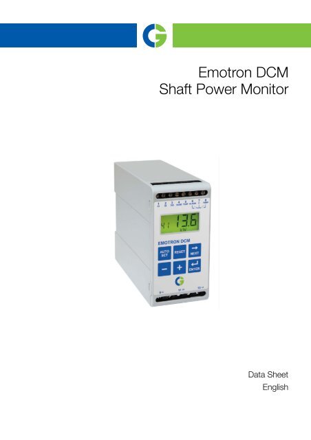
Technical Data45 x 90 x 115 mm (1.77" x 3.54" x 4.53")Dimension (WxHxD)35 mm(1.38 ’‘ )26 mm(1.02 )’‘90 mm (3.54 )’‘45 mm (1.77’‘ )115 mm (4.53 ’‘)Mounting 35 mm DIN rail 46277WeightSupply voltage (VAC)0.3 kg (10.5 oz)3x100to240,3 x 380 to 500,3 x 525 to 690 (±10%)NOTE: that these are separate voltage units; see table with order numbers on page 4.FrequencyCurrent input<strong>Power</strong> consumptionStart-up delayStop delayDigital input terminal 3Temperature input terminal 5Relay outputFuseTerminal wire sizeTerminal tightening torqueRepeatabilitypower measurement45 to 65 HzCurrent transformer CTM010, 025, 050 or 100. (If rated current >100 A, CTM010 and astandard transformer)6VA max.1to170s1to90 sFor closing contact. Internal supply 15 - 30 VDC, shortcircuitcurrent 10 - 20 mAInternal supply 15-30 VDC, short-circuit current 2 mA - 2.5 mA5 A 240 VAC Resistive. 1.5 A 240 VAC Pilot duty/AC1210 A max.Use 75ºC copper (CU) wire only. 0.2 to 4.0 mm² single core (AWG12), 0.2 to 2.5 mm²flexible core (AWG14), stripped length 8 mm (0.32").0.56 - 0.79Nm (5-7 Ib-in)±1 unit 24 h; +20ºC (+68ºF)Temperature tolerance < 0.1% / ºCOperating temperature rangeStorage temperature rangeProtection classRoHS directiveApproved to-20ºC to +50ºC (-4ºF to +122ºF)-30ºC to +80ºC (-22ºF to +176ºF)IP202002/95/ECCE (up to 690 VAC), UL and cUL (up to 600 VAC)3 CG Drives & Automation 01-5964-01r0
Ordering numbersOrdering numberDesignation01-2110-25 <strong>Emotron</strong> <strong>DCM</strong> 3x100-240 VAC01-2110-45 <strong>Emotron</strong> <strong>DCM</strong> 3x380-500 VAC01-2110-55 <strong>Emotron</strong> <strong>DCM</strong> 3x525-690 VACTechnical Data for Current TransformerType Dimensions (WxØ) Weight* MountingCTM 010 27 (35) x Ø48 mm 0.20 kg 35 mm DIN rail 46277CTM 025 27 (35) x Ø48 mm 0.20 kg 35 mm DIN rail 46277CTM 050 27 (35) x Ø48 mm 0.20 kg 35 mm DIN rail 46277CTM 100 45 (58) x Ø78 mm 0.50 kg 35 mm DIN rail 46277*)Weight including 1 m (39 inch) cable. Please note that themaximum length of the CTM cable is 1 m and this cable mustnot be extended.4. 310. 31748274235784535Fig. 3Current transformer, CTM xxx.CG Drives & Automation 01-5964-01r0 4
Accessories and documentationOrdering numberDesignation01-2471-10 Current Transformer (CT) CTM010, max. 10 A01-2471-20 Current Transformer (CT) CTM025, max. 25 A01-2471-30 Current Transformer (CT) CTM050, max. 50 A01-2471-40 Current Transformer (CT) CTM100, max. 100 A01-2368-00 Front Panel Kit 1 (2 x terminal covers included)01-4136-01 2 x Terminal covers01-5965-00 Instruction manual (Swedish)01-5965-01 Instruction manual (English)EU (European Union) specificationsEN 61000-6-3EMCEN 61000-6-2EN 61000-4-5Electrical safety EN 60947-5-1Rated insulated voltage690 VRated impulse withstand voltage 4000 VPollution degree 2Terminals 3, 4 and 5 are basic insulated from the line and relay terminals.5 CG Drives & Automation 01-5964-01r0
Window ParametersTable 3Window parameters and defaultsWindow Function Value DefaultCustom settingMasterSlave00010203040506Alarm indication. Flashes when alarm present (windowbecomes active only on alarm).Symbolflashing.Remaining time to next pump start. Standard window duringpause. When the <strong>DCM</strong> is SLAVE - - - appears.Symbolflashing and m (min) or s (second).Pumping Time (PT) since the last pump start. Displayedwhen pumping. When the <strong>DCM</strong> is MASTER and the <strong>DCM</strong>SLAVE is pumping - - - appears.Symbolflashing and m (min) or s (seconds).Pumping Time (PT) after last pump start when the pump isstarted on high-level switch. Displayed when pumping afterhigh-level switch.Symbolflashing and m (min) or s (seconds).Measured power as percentage of the <strong>DCM</strong>’s measurementrange.Symbol %.Measured line voltage.Symbol V.Measured peak power as percentage of the <strong>DCM</strong> measurementrange. Press - and + (in this window) simultaneouslyfor 3 seconds to reset the value.Symbol %.720 - 15 min.900 to 0 s0 to 90 s.15 - 720 min.12 to 999 h0 to 900 s15 - 720 min.12 to 999 h0 to 125%0 to 999 V0 to 125% 0%0708Total pumping time in hours. Press - and + (in this window)simultaneously for 3 seconds to set the value to 0.Symbol .Total number of pump starts. Press - and + (in this window)simultaneously for 3 seconds to set the value to 0.0-99999 00-99999 009Parameter lock.Symbol . Is displayed when parameter is locked.0 to 99911 Stop level. Symbol %. 0 to 125% 0%12 Snore margin. Symbol %. 0 to 125% 4%13212223Type of Auto set. Auto set when the pump is snoring (_)(No liquid in the pit).Auto set when the pump is not snoring ( - )(Liquid in the pit).Pit volume and level setting, see Fig. 11, page 23 and Fig.14, page 32. See also note on page 22. NOTE! The windowis not shown when the <strong>DCM</strong> is SLAVE.Maximum pause time.NOTE! The window is not shown when the <strong>DCM</strong> is SLAVE.Symbol .Start-up delay.Symbol .( - ) or (_) ( - )1.0 to 10.0 1.00 to 900 s15 - 720 min.1to170s600 s5sCG Drives & Automation 01-5964-01r0 6
Table 3Window parameters and defaultsWindow Function Value DefaultCustom settingMasterSlave243132Stop delay.Symbol .High temperature on pump motor or motor protectionalarm, terminal 5 (on). Turn off (OFF).Latched alarm, terminal 5 (on).Alarm not latched (OFF). Can only be used when window 31is (on).1to90son / OFFon / OFF41 Phase asymmetry permitted. OFF/ 5 to 50% 10%42515253617172Phase asymmetry latched alarm (on). Phase asymmetryalarm not latched. (OFF) Can be used when window 41 isset between 5-50%.Alarm relay (terminal 6 ALARM).NC: normally closed,NO: normally open.The window isn’t shown when <strong>DCM</strong> is MASTEROperating relay to control the pump motors contactor(terminal 8 PUMP).NC: Relay contact is closed when pump is pumping.NO: Relay contact is open when pump is pumping.Digital input for closingcontact:1 High-level switch2 External reset3 External Auto set (not usedin dual-pump system).Measured current on theterminals S1 and S2.Desired <strong>DCM</strong> function:1 Single-pump system2 Dual-pump system MASTER3 Dual-pump system SLAVE.Pump alternating:(on) Alternate by each pump cycle (OFF) The SLAVE <strong>DCM</strong>only starts when the <strong>DCM</strong> MASTER indicates a fault code.NOTE! The window is not shown when the <strong>DCM</strong> is SLAVE.on / OFFNC/NONC/NO0-70 mA2sOFFOFFOFFNONC11, 2, 3 1on/OFFOFF73Pump starts on high-level switch. (on) Both pumps start.(OFF) one pump starts.NOTE! Window is not shown when the <strong>DCM</strong> is SLAVE.on/OFFOFF99 Default settings (dEF). User adjustments mode (USr). dEF/USr dEF7 CG Drives & Automation 01-5964-01r0
CG Drives & Automation Sweden ABMörsaregatan 12Box 222 25SE-250 24 HelsingborgSwedenT +46 42 16 99 00F +46 42 16 99 49www.emotron.com / www.cgglobal.comCG Drives & Automation, 01-5964-01r0 2013-05-15


