


You also want an ePaper? Increase the reach of your titles
YUMPU automatically turns print PDFs into web optimized ePapers that Google loves.
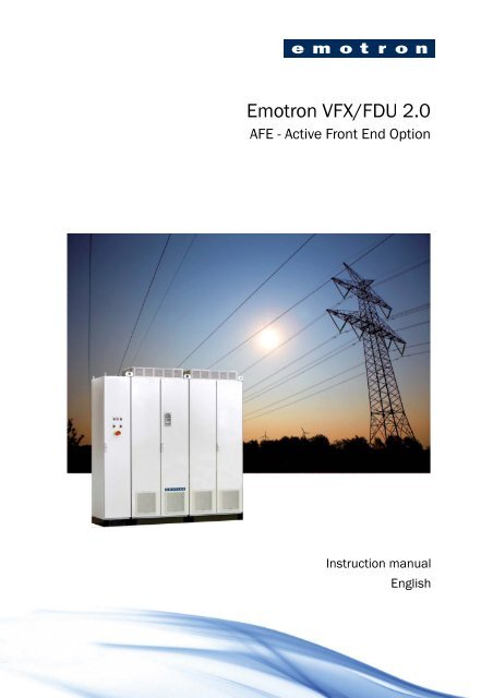
<strong>Emotron</strong> <strong>VFX</strong>/<strong>FDU</strong> <strong>2.0</strong>AFE - Active Front End OptionInstruction manualEnglish
<strong>Emotron</strong> <strong>VFX</strong>/<strong>FDU</strong> <strong>2.0</strong>AFE - Active Front End OptionInstruction manual - EnglishDocument number: 01-5076-01Edition: R1Date of release:26-10-2011© Copyright <strong>Emotron</strong> AB 2011<strong>Emotron</strong> retains the right to change specifications and illustrations in thetext, without prior notification. The contents of this document may notbe copied without the explicit permission of <strong>Emotron</strong> AB.
CondensationIf the active front end or motor inverter is moved from acold (storage) room to a room where it will be installed,condensation can occur. This can result in sensitivecomponents becoming damp. Do not connect the mainsvoltage until all visible dampness has evaporated.Incorrect connectionThe active front end or motor inverter drive is not protectedagainst incorrect connection of the mains voltage, and inparticular against connection of the mains voltage to themotor outlets U, V and W. The active front end or motorinverter can be damaged in this way.Power factor capacitors for improvingcosRemove all capacitors from the motor and the motor outlet.Precautions during AutoresetWhen the automatic reset is active, the motor will restartautomatically provided that the cause of the trip has beenremoved. If necessary take the appropriate precautions.TransportTo avoid damage, keep the active front end and motorinverter in its original packaging during transport. Thispackaging is specially designed to absorb shocks duringtransport.IT Mains supplyThe active front end can be modified for an IT mainssupply, (non-earthed neutral), please contact your supplierfor details.Heat warningBe aware of specific parts on the Active frontend and motor inverter having hightemperature.DC-link residual voltageWARNING: After switching off the mainssupply, dangerous voltage can still bepresent in the Active front end-AFR or motorinverter-AC drive. When openingtheequipment for installing and/or commissioningactivities wait at least 5 minutes. In case of malfunctiona qualified technician should check the DC-link or waitfor one hour before dismantling the AFR or AC drive forrepair.<strong>Emotron</strong> AB 01-5076-01r1
ContentsSafety InstructionsContents.......................................................... 11. Introduction..................................................... 31.1 Delivery and unpacking ............................................ 31.2 Using of the instruction manual............................... 31.3 Type code number..................................................... 31.4 Standards .................................................................. 41.5 Dismantling and scrapping....................................... 51.6 Glossary ..................................................................... 52. General description ........................................ 72.1 AC drive types............................................................ 72.2 <strong>Emotron</strong> AFR cabinet concept.................................. 92.3 <strong>Emotron</strong> AFR features............................................. 103. Mounting ...................................................... 133.1 Lifting instructions................................................... 133.2 Cabinet mounting.................................................... 144. Installation ................................................... 154.1 Before installation................................................... 154.2 Connect motor and mains...................................... 154.3 Cable specifications................................................ 169.4 I/Os and Virtual Connections [500]....................... 369.5 Logical Functions and Timers [600] ...................... 369.6 View Operation/Status [700] ................................. 369.7 View Trip Log [800] ................................................. 389.8 System Data [900].................................................. 399.9 AFR Option [O00] .................................................... 3910. Troubleshooting, Diagnoses andMaintenance ................................................ 4510.1 Trips, warnings and limits....................................... 4510.2 Trip conditions, causes and remedial action ........ 4510.3 Maintenance ........................................................... 4911. Technical Data ............................................. 5111.1 Electrical and mechanical specificationsrelated to model...................................................... 5111.2 General electrical specifications............................ 5411.3 Operation at higher temperatures ......................... 5511.4 Environmental conditions....................................... 5511.5 Control signals......................................................... 5612. Menu List ...................................................... 575. Control Connections for <strong>Emotron</strong> <strong>VFX</strong>Rand <strong>FDU</strong>L...................................................... 175.1 Terminal connections for AFR ................................ 185.2 Connecting the Control Signals.............................. 195.3 Connecting options ................................................. 206. Getting Started ............................................ 216.1 Connect the mains and motor cables.................... 216.2 Using the function keys .......................................... 216.3 Remote control........................................................ 227. EMC and Machine Directive ....................... 257.1 EMC standards........................................................ 257.2 Stop categories and emergency stop .................... 258. Operation via the Control Panel ................. 278.1 Control panels ......................................................... 278.2 General .................................................................... 278.3 The control panel .................................................... 288.4 The menu structure................................................. 318.5 Programming during operation .............................. 318.6 Editing values in a menu ........................................ 328.7 Copy current parameter to all sets ........................ 328.8 Programming example............................................ 329. Functional Description for AFR unit .......... 339.1 Preferred View [100]............................................... 339.2 Main Setup [200].................................................... 349.3 Process and Application Parameters [300] .......... 36<strong>Emotron</strong> AB 01-5076-01r1 1
2 <strong>Emotron</strong> AB 01-5076-01r1
1.5 Dismantling and scrappingThe enclosures of the drives are made from recyclablematerial as aluminium, iron and plastic. Each drive containsa number of components demanding special treatment, forexample electrolytic capacitors. The circuit boards containsmall amounts of tin and lead. Any local or nationalregulations in force for the disposal and recycling of thesematerials must be complied with.1.5.1Disposal of old electrical andelectronic equipmentThis information is applicable in the European Union andother European countries with separate collection systems.This symbol on the product or on its packaging indicatesthat this product shall be taken to the applicable collectionpoint for the recycling of electrical and electronicequipment. By ensuring this product is disposed of correctly,you will help prevent potentially negative consequences forthe environment and human health, which could otherwisebe caused by inappropriate waste handling of this product.The recycling of materials will help to conserve naturalresources. For more detailed information about recyclingthis product, please contact the local distributor of theproduct.1.6 Glossary1.6.1Abbreviations and symbolsIn this manual the following abbreviations are used:Table 2Abbreviation/symbolAFEAFRDFE<strong>VFX</strong>R<strong>FDU</strong>LAC driveVSILCL-filterTHDCPEIntUIntIntLongAbbreviationsActive front endDescriptionRegenerative active front endDiode front endRegenerative <strong>VFX</strong> driveLow harmonic <strong>FDU</strong> driveFrequency converterVoltage source inverter (motor inverter)Induction - Capacitance - Induction filterTotal harmonic distortionControl panel, the programming and presentationunit on the unitCommunication formatCommunication format (Unsigned integer)Communication format (Integer)Communication format (4 byte integer)The function cannot be changed in run mode1.6.2 DefinitionsIn this manual the following definitions for current, torqueand frequency are used:Table 3DefinitionsName Description QuantityI IN Nominal input current of AFR A RMSI NOM Nominal output current of VSI A RMSI MOT Nominal motor current A RMSP NOM Nominal power of VSI kWP MOT Motor power kWT NOM Nominal torque of motor NmT MOT Motor torque Nmf OUT Output frequency of VSI Hzf MOT Nominal frequency of motor Hzn MOT Nominal speed of motor rpmI CL Maximum output current A RMSSpeed Actual motor speed rpmTorque Actual motor torque Nm<strong>Emotron</strong> AB 01-5076-01r1 Introduction 5
2. General description<strong>Emotron</strong> AFR is a regenerative active front end (AFE) unitdesigned to be used together with <strong>Emotron</strong> motor inverters(VSIs), i.e. <strong>VFX</strong> or <strong>FDU</strong>, to comprise a complete VSI.<strong>Emotron</strong> AFR consists of an active rectifier module and aLCL-filter. The main objective of <strong>Emotron</strong> AFR is to rectifythe supply AC voltage into DC voltage to be fed to orregenerated from the VSIs. This is achieved with minimalimpact on the supply by the control of the active rectifiermodule which provides sinusoidal input currents with a verylow harmonic content, typically a THD(I) below 5%.!CAUTION!Always consult <strong>Emotron</strong> before connectingan AFR to a standard VSI.2.1 AC drive types2.1.1 Standard AC drive(ascomparison)A standard AC driveconsists of a rectifier module and aninverter module. The rectifier module (front-end) consists ofa 6-pulse diode bridge, i.e. diode front-end (DFE) while theinverter module (VSI) consists of IGBTs with anti-parallelfree wheeling diodes, see Fig. 2. The main advantages ofDFEs are the simple and robust design together with theirhigh efficiency, i.e. low losses. The main disadvantages areunidirectional power flow and the high harmonic content inthe line current, typically THD 30- 40%.Fig. 2Standard AC drive.<strong>Emotron</strong> AB 01-5076-01r1 General description 7
2.1.2 AC drive with AFR (as thisdelivery)An AFR unit is basically a VSI towards the supply (via afilter) where the IGBTs are used as an active rectifier, see Fig.3. The main advantages are inherent 4Q-operation, i.e.bi-directional power flow, and sinusoidal supply currents,i.e. low harmonics.AFR = AFE + LCL - filterVSIFig. 3VSI with AFR.The AFR unit is controlled in such a way to keep the energybetween motor and supply in balance. This is achieved bycontrolling the DC-link voltage (Udc). Other features arethe possibility for reactive power compensation and boostedDC-link voltage.8 General description <strong>Emotron</strong> AB 01-5076-01r1
2.2 <strong>Emotron</strong> AFR cabinet concept2.2.1 Single drive applicationsThe <strong>Emotron</strong> regenerative AC drive, i.e. <strong>VFX</strong>R, iscomprised by an AFR unit, i.e. AFE and filters, and a VSI,i.e. <strong>Emotron</strong> <strong>VFX</strong> or <strong>FDU</strong>. The concept is designed as acabinet solution, see Fig. 4 ,CBSBSCBFig. 4Single drive in cabinetwhere• Cabinet - IP54 cabinet with door fans• Q1 - Circuit breaker• K1 - Main contactor• RFI - EMC filter• LCL - LCL filter• F2 - MCB(Miniature circuit breaker)for pre-chargecircuit• AFE - <strong>Emotron</strong> AFE module with 24V standby supplyboardand integrated pre-charge circuit (K2,D2,R2)• AFR - <strong>Emotron</strong> AFE and filters• VSI - DC-voltage fed VSI module, i.e. <strong>Emotron</strong> <strong>VFX</strong> or<strong>FDU</strong>• CB - Control board• SBS - Standby supply board• Lo - Output coil2.2.2 Common DC-bus applicationsFor common DC-bus applications, the cabinet will containonly the AFR part of Fig. 4, i.e. all except the VSI & Lo.<strong>Emotron</strong> AB 01-5076-01r1 General description 9
2.3 <strong>Emotron</strong> AFR features2.3.1 Power-up and DC-link chargingPower up and charge control of the <strong>Emotron</strong> AFR andDC-link (U dc ) is handled via the dedicated control board(CB) relays 1 and 3, where Charge contactor (K2) control isfixed to CB Relay1 and Main contactor (K1) is fixed to CBRelay3.Typical charge time is 3-5s and an additional delay after K1activation of 1s is added before Run (or Auto ID) commandis acknowledged.Fig. 5UdcUdc,refUdc PICB DI1: RunCB DI1: EnableCB Re 1: Charge (K2)CB Re 2: Option (OK)CB Re 3: Main (K1)DC-link voltage (U dc ) charge control.Optional signal Running OK, i.e. U dc under control, issignaled via default CB Relay2 selection ‘Option’ and ispreferably used to enable the VSIs in order to interlock theAFR and VSIs. Typical time delay is
12 General description <strong>Emotron</strong> AB 01-5076-01r1
RITTALRITTALRITTALRITTALRITTAL3. MountingThis chapter describes how to mount the AC drive.Before mounting it is recommended that the installation isplanned first.• Be sure that the AC drive suits the mounting location.• The mounting site must support the weight of the ACdrive.• Will the AC drive continuously withstand vibrationsand/or shocks?• Check ambient conditions, ratings, required cooling airflow, compatibility of the motor, etc.• Know how the AC drive will be lifted and transported.Lifting eyesA°3.1 Lifting instructionsThe easiest way to move or lift the equipment is to use thelifting eyes on top of the cabinet, see Fig. 7.When lifting, be carful not to damage the air outlets.Note: To prevent personal risks and any damage to theunit during lifting, it is advised to use the lifting eyes ontop of the equipment.Air outlet21Lifting eyeFig. 8Remove the roof unit and use the lifting eyes to liftsingle unit 600mm and 900mm.Single cabinet drives can be lifted/transported safely using theeyebolts supplied and lifting cables/chains as inillustration Fig. 8 above.Depending on the cable/chain angle A (in Fig. 8),following loads are permitted:Cable/chain angle APermitted load45 ° 4 800 N60 ° 6 400 N90 ° 13 600NRegarding lifting instructions for other cabinet sizes, pleasecontact <strong>Emotron</strong>.Fig. 7Use the lifting eyes.<strong>Emotron</strong> AB 01-5076-01r1 Mounting 13
3.1.1 CoolingTable below shows the minimum free space required aroundthe AFR and/or VSI cabinets in order to guarantee adequatecooling. Because the fans blow the air from the bottom to thetop it is advisable not to position an air inlet immediatelyabove an air outlet.The following minimum separation between two cabinets ora cabinet and a non-dissipating wall must be maintained.Valid if free space on opposite side.3.2.2 Mounting schemesNOTE: When a cabinet is placed between two walls, aminimum distance at each side of 200 mm must bemaintained.3.2 Cabinet mounting3.2.1 CoolingIf the AFR or VSI is installed in a cabinet, the rate of airflowsupplied by the cooling fans must be taken intoconsideration. Frame sizes are listed in chapter 11.1 page 51.Table 5Flow rates cooling fansFrame Model Flow rate [m 3 /hour]E46 175 510F46 250F69* 175800G46 375 1020H46 500H69* 3751600I46 750I69* 5002400J46 1000J69* 6503200K46 1500K69* 10004800Fig. 9 <strong>VFX</strong>R/<strong>FDU</strong>L46: Model 146 to 250*Preliminary data.NOTE: For the models 1000 to 1500 the mentionedamount of air flow should be divided equally over the twocabinets.Fig. 10 <strong>VFX</strong>R/<strong>FDU</strong>L46: Model 300 to 50014 Mounting <strong>Emotron</strong> AB 01-5076-01r1
4. InstallationThe description of installation in this chapter complies withthe EMC standards and the Machine Directive.Select cable type and screening according to the EMCrequirements valid for the environment where the AFR andVSI is installed.!CAUTION!Allways consult <strong>Emotron</strong> before connectingan AFR to a standard AC drive.4.1 Before installationRead the following checklist and prepare for yourapplication before installation.• Local or remote control.• Functions used.• Suitable AFR and VSI size in proportion to the motor/application.• Mount separately supplied option boards according tothe instructions in the appropriate option manual.If the AFR and AC drive is temporarily stored before beingconnected, please check the technical data for environmentalconditions. If the AFR and VSIis moved from a cold storageroom to the room where it is to be installed, condensationcan occur on it. Allow the AFR and VSI to become fullyacclimatised and wait until any visible condensation hasevaporated before connecting the mains voltage.4.2 Connect motor and mains4.2.1 Single drivesAFEVSIBlankpanelControlpanel forAFEMains connectionMotor connectionL1, L2, L3 U, V, WFig. 11 Connecting motor and mains cables for<strong>VFX</strong>R/<strong>FDU</strong>L46 - 146 to 250Table 6L1,L2,L3PEU, V, WDC-,DC+Mains and motor connectionMains supply, 3 -phaseSafety earth (protective earth)Motor earthMotor output, 3-phaseDC-linkconnections (optional)<strong>Emotron</strong> AB 01-5076-01r1 Installation 15
5. Control Connections for <strong>Emotron</strong> <strong>VFX</strong>R and <strong>FDU</strong>LFig. 13 shows typical control signal connections required forbasic functionality. For more detailed information, seedrawings in cabinet and instruction manual for<strong>Emotron</strong> <strong>VFX</strong>, chapter “Control connections”.WARNING!Always switch off the mains voltage and waitat least 7 minutes to allow the DC capacitorsto discharge before connecting the controlsignals or changing position of any switches. If theoption External supply is used, switch of the mains tothe option. This is done to prevent damage on thecontrol board.<strong>VFX</strong>R/<strong>FDU</strong>Lcustomer terminalsRelay 3Main contactorDigIn 2RunRDigIn 8ResetDigOut 2OperationRelay 1Charge relayDigOut 1OptionEnableDigIn 3ResetDigIn 3EnableDigOut 2LZOffDigIn 724 VStart0VSpeedReference4-20 mA+Fig. 13 Recommended control signals<strong>Emotron</strong> AB 01-5076-01r1 Control Connections for <strong>Emotron</strong> <strong>VFX</strong>R and <strong>FDU</strong>L 17
5.1 Terminal connections forAFRThe terminal strip for connecting the control signals isaccessible after opening the front doorThe table describes the default functions for the signals. Theinputs and outputs are programmable for other functions asdescribed in chapter 9. page 33. For signal specificationsrefer to chapter 11. page 51.For VSI, refer to instruction manual for <strong>Emotron</strong> <strong>FDU</strong> or<strong>VFX</strong>.NOTE: The maximum total combined current for outputs11, 20 and 21 is 100mA.Table 8Control signals for AFRTerminal Name Function (Default)Outputs1 +10 V +10 VDC supply voltage6 -10 V -10 VDC supply voltage7 Common Signal ground11 +24 V +24 VDC supply voltage12 Common Signal ground15 Common Signal groundDigital inputs8 DigIn 1 RunL (reverse)9 DigIn 2 RunR (forward)10 DigIn 3 Enable16 DigIn 4 Off17 DigIn 5 Off18 DigIn 6 Off19 DigIn 7 Off22 DigIn 8 RESETDigital outputs20 DigOut 1Option(Active when AFR is running)21 DigOut 2 LZ (Trip pulse of 1s)Analogue inputs2 AnIn 1 Process Ref3 AnIn 2 Off4 AnIn 3Dedicated for supply voltagemeasurement option.5 AnIn 4Dedicated for supply voltagemeasurement option.Analogue outputs13 AnOut 1 0 to nominal current14 AnOut 2 0 to max torqueRelay outputs31 N/C 1Relay 1 output32 COM 1 Dedicated for Charge33 N/O 1contactor K2.41 N/C 2Relay 2 output42 COM 2 Option (Active when the AFR is43 N/O 2running).51 COM 3 Relay 3 output52 N/O 3 Dedicated for Main contactor K1NOTE: N/C is opened when the relay is active and N/O isclosed when the relay is active.18 Control Connections for <strong>Emotron</strong> <strong>VFX</strong>R and <strong>FDU</strong>L <strong>Emotron</strong> AB 01-5076-01r1
RITTALRITTALRITTALRITTALRITTALRITTALRITTALRITTAL5.2 Connecting the ControlSignals5.2.1 CablesThe standard control signal connections are suitable forstranded flexible wire up to 1.5 mm 2 and for solid wire up to2.5 mm 2 .Control signalsconnectionScreeningconnectionMain switch Q1Fig. 14 Connecting the control signals <strong>VFX</strong>R/<strong>FDU</strong>L46 -146to 250.Control signalsconnectionScreeningconnectionMain switch Q1Fig. 15 Connecting control signal <strong>VFX</strong>R/<strong>FDU</strong>L46-300 to500.L2L1MotorMotorNOTE: The screening of control signal cables isnecessary to comply with the immunity levels given inthe EMC Directive (it reduces the noise level).NOTE: Control cables must be separated from motor andmains cables.5.2.2 Types of control signalsAlways make a distinction between the different types ofsignals. Because the different types of signals can adverselyaffect each other, use a separate cable for each type. This isoften more practical because, for example, the cable from apressure sensor may be connected directly to the motorinverter.We can distinguish between the following types of controlsignals:Analogue inputsVoltage or current signals, (0-10 V, 0/4-20 mA) normallyused as control signals for speed, torque and PID feedbacksignals.Analogue outputsVoltage or current signals, (0-10 V, 0/4-20 mA) whichchange slowly or only occasionally in value. In general, theseare control or measurement signals.DigitalVoltage or current signals (0-10 V, 0-24 V, 0/4-20 mA)which can have only two values (high or low) and onlyoccasionally change in value.DataUsually voltage signals (0-5 V, 0-10 V) which change rapidlyand at a high frequency, generally data signals such asRS232, RS485, Profibus, etc.RelayRelay contacts (0-250 VAC) can switch highly inductiveloads (auxiliary relay, lamp, valve, brake, etc.).SignaltypeMaximum wire size Tighteningtorque0.5 NmAnalogue Rigid cable:Digital0.14-2.5 mm 2Flexible cable:Data 0.14-1.5 mm 2Relay 0.25-1.5 mm 2Cable with ferrule:Cable typeScreenedScreenedScreenedNot screenedExample:The relay output from a motor inverter which controls anauxiliary relay can, at the moment of switching, form asource of interference (emission) for a measurement signalfrom, for example, a pressure sensor. Therefore it is advisedto separate wiring and screening to reduce disturbances.<strong>Emotron</strong> AB 01-5076-01r1 Control Connections for <strong>Emotron</strong> <strong>VFX</strong>R and <strong>FDU</strong>L 19
5.2.3 ScreeningFor all signal cables the best results are obtained if thescreening is connected to both ends: the VSI side and at thesource (e.g. PLC, or computer). See Fig. 16.It is strongly recommended that the signal cables be allowedto cross mains and motor cables at a 90 angle. Do not letthe signal cable go in parallel with the mains and motorcable.5.2.4 Single-ended or double-endedconnection?In principle, the same measures applied to motor cablesmust be applied to all control signal cables, in accordancewith the EMC-Directives.For all signal cables as mentioned in section 5.2.2 the bestresults are obtained if the screening is connected to bothends. See Fig. 16.NOTE: Each installation must be examined carefullybefore applying the proper EMC measurements.5.2.5 Current signals ((0)4-20 mA)A current signal like (0)4-20 mA is less sensitive todisturbances than a 0-10 V signal, because it is connected toan input which has a lower impedance (250 ) than avoltage signal (20 k). It is therefore strongly advised to usecurrent control signals if the cables are longer than a fewmetres.5.2.6 Twisted cablesAnalogue and digital signals are less sensitive to interferenceif the cables carrying them are “twisted”. This is certainly tobe recommended if screening cannot be used. By twistingthe wires the exposed areas are minimised. This means thatin the current circuit for any possible High Frequency (HF)interference fields, no voltage can be induced. For a PLC itis therefore important that the return wire remains inproximity to the signal wire. It is important that the pair ofwires is fully twisted over 360°.5.3 Connecting optionsSee instruction manual for <strong>Emotron</strong> <strong>VFX</strong> <strong>2.0</strong> for how toconnect option cards.Control boardPressuresensor(example)External control(e.g. in metal housing)Control consolFig. 16 Electro Magnetic (EM) screening of control signalcables.20 Control Connections for <strong>Emotron</strong> <strong>VFX</strong>R and <strong>FDU</strong>L <strong>Emotron</strong> AB 01-5076-01r1
6. Getting StartedThis chapter is a step by step guide that will show you thequickest way to get the motor shaft turning. We will showyou setup with remote control.We assume that the AFR and VSI is mounted in a cabinet asin the chapter 3. page 13.First there is general information of how to connect mains,motor and control cables. The next section describes how touse the function keys on the control panel. The subsequentremote control example describe how to program/set themotor data and run the AFR, the VSI and motor.6.1 Connect the mains andmotor cablesDimension the mains and motor cables according to localregulations. The cables must be able to carry the AFR andVSI load current.Connect mains cables and motor cables according to chapter4.2 page 15.6.2 Using the function keysFor more information regarding the control panel and menusystem, see chapter 8. page 27NEXT100 200 300ENTER210PREVNEXTENTER240241ENTERFig. 17 Example of menu navigation when entering motorvoltageESCENTERESCstep to lower menu level or confirm changed settingstep to higher menu level or ignore changed settingNEXTstep to next menu on the same levelPREVstep to previous menu on the same levelincrease value or change selectiondecrease value or change selection<strong>Emotron</strong> AB 01-5076-01r1 Getting Started 21
6.3 Remote controlIn this example external signals, an external start button andan analogue reference, are used to control the VSI andmotor. The AFR is controlled from the VSI.In order to perform the setup examples, you will use thecontrol panels for the AFR (inside cabinet) and VSI (cabinetdoor), see Fig. 20, page 27. For further information aboutthe control panel (CP) and menu structure, see chapter 8.page 27.6.3.1 Set up AFRWARNING!Always switch off the mains voltage beforeopening the drive unit and wait at least 7minutes to allow the buffer capacitors todischarge.Make sure that the main supply is switched off and open the<strong>VFX</strong>R/<strong>FDU</strong>L door. Check wiring according to Fig. 13, page17.NOTE: Wiring is pre-made from factory.In this case, wiring is made for Charge method[O21] "Supply-NC" via NC terminal (31) on CB Relay 1.1. If other Charge method [O21] than default "Supply-NC" = Charge at power supply via NC terminal onRelay 1 is to be used thena) Connect Charge Relay control signal toNO terminal (33)b) Connect external 24V supply. Required for allCharge methods [O21] using NO terminal (33).c) Setup required Charge method [O21].2. Switch on the power supply. Once the mains is switchedon, the internal fans of the AFR and VSI will run for 5seconds. Menu [100] Preferred view is displayed in CPafter power up.Warning!While power is supplied to the inverter, do nottouch any terminal or internal part of theinverter. Do not connect or disconnect anywire or connector. Otherwise, you run the risk of electricshock resulting in serious injury!In addition this could cause serious damage to theactive front end or motor inverter.displayed),press to continue.RESETe) Verify the new settings for [O11]-[O14].f) Mains supply voltage [O11] can preferably bemanually set back to the average mains supplyvoltage value after ID-run. This is recommended ifthe mains supply voltage fluctuates much over time.4. For 1st run, setup AFE to start from CP.a) Set Reference control [214] to "Keyboard"b) Set Run/Stop control [215] to "Keyboard"c) Set Reset control [216] to "Keyboard"d) Set Process Ref [310] to 0%.e) Disable reactive power compensation by settingQ max [O41] to 0%.f) Start AFR by pressing or . Note thatthe both run directions, i.e. RunR and RunL, areaccepted independent of the actual phase sequence.g) Verify operation via menus [710].h)Stop AFR by pressing Stop/Reset.5. Setup AFR to start from VSI command via I/O.a) Change Ref control [214] to "Remote"b) Change Run/Stop control [215] to "Remote"c) Change Reset control [216] to "Remote" or"Remote+Keyb"d) Verify default parameter setup according toTable 9 below.Table 9Default parameter setup for AFRParameter Setup Comment[551] Relay 1ChargeK2[552] Relay 2 Option[553] Relay 3 Main K1[523] DigIn 3 Enable[214] Ref Control Remote[215] Run/Stp Ctrl Remote[216] Reset Ctrl Remote[310] Set/View ref 0%[522] DigIn 2 RunR[528] DigIn 8 Reset[541] DigOut 1 Option[542] DigOut 2 LZCabinet hardwarecontrol/feedbackAFE command setupQ (cos φ) referenceAFE/VSI command/feedback3. Perform a supply ID-run [O15]a) [Set [O15] Supply ID run to On, confirm withb) Give start commandc) The AFE will now measure and setup supplyparameters* [O11] Supply volatge* [O13] Supply frequency* [O14] Supply phase sequenced) After successful ID-run ("Test Run OK" isENTER22 Getting Started <strong>Emotron</strong> AB 01-5076-01r1
Table 9Default parameter setup for AFRParameter Setup Comment[651] Timer2 Trig Trip[652] Timer2Mode[653] Timer2DelayDelay[6151] CD1 Trip[6151] CD2 T2Q[630] Logic Z00:00:01CD1 &!D2AFE 1s trip pulse6. Now the AFR is set to be controlled from the VSI7. Close the AFR cabinet door.6.3.2 Set up VSIMenu [100], Preferred View is displayed when started.1. Enter correct motor data for the connected motor. Themotor data is used in the calculation of completeoperational data in the VSI.a) Set motor voltage [221]b) Set motor frequency [222]c) Set motor power [223]d) Set motor current [224]e) Set motor speed [225]f) Set motor power factor (cos ) [227]g) Select supply voltage level used [21B]h) [229] Motor ID run: Choose Short, confirm withENTER and give start command .The VSI will now measure some motorparameters. The motor makes some beeping soundsbut the shaft does not rotate. When the ID run isfinished after about one minute ("Test Run OK!" isdisplayed), press to continue.RESET2. Use AnIn1 as input for the reference value. The defaultrange is 4-20 mA. If you need a 0-10 V reference value,change switch (S1) on control board and set[512] Anln 1 Set-up to 0-10V.3. Setup VSI to control the AFR via I/O, see Table 10.a) Set digital output 2 [542] to "Operation". Gives startcommand to AFR from VSI.b) Set digital input 3 [523] to "Enable". Feedback toVSI that AFR is running.c) Adapt AFR trip pulse polarity for VSI Extern Trippolarity* Set digital input 7 [527] to "Off". Feedback to VSIthat AFE is tripped (pulse if 1s).* Set digital comparator 1 [6151] to "DigIn7".* Set virtual I/O 1 Source [562] to "!D1".* Set virtual I/O 1 Destination [561] to "Ext Trip".see Table 10.Table 10 Default parameter setup for VSI (<strong>VFX</strong>/<strong>FDU</strong> <strong>2.0</strong>)Parameter Setup Comment[542 DigOut 2 Operation Command AFE run[523] DigIn 2 Enable Feedback AFE running[527] DigIn 7 Off[6151] CD 1 DigIn 7[561] VIO 1 Dest4. Switch off power supply.5. Connect digital and analogue inputs/outputs as inFig. 16.a)Connect a reference value between terminals 7(Common) and 2 (AnIn 1).b)Connect an external start button between terminal11(+24 VDC) and 9 (DigIn2, RUNR).c)Connect a reset signal between terminal 11(+24 VDC) and 22 Reset.XD4+ 0VReference4-20 mAFig. 18 WiringExternaltripFeedback AFE trip viaExt TripWARNING!Always switch off the mains voltage beforeopening the drive unit and wait at least 7minutes to allow the buffer capacitors todischarge.StartReset6. Close the door and switch on the power supply. Oncethe mains is switched on, the internal fans of the AFRand VSI will run for 5 seconds. Menu [100] Preferredview, is displayed in the Control panel after power up.6.3.3 Run the VSINow the installation is finished, and you can press theexternal start button to start the motor.When the AFR, VSI and motor are running the mainconnections are OK.XD5XD3<strong>Emotron</strong> AB 01-5076-01r1 Getting Started 23
24 Getting Started <strong>Emotron</strong> AB 01-5076-01r1
7. EMC and Machine Directive7.1 EMC standardsThe active front end and variable speed drive complies withthe following standards:EN(IEC)61800-3:2004 Adjustable speed electronic powerdrive systems, part 3, EMC product standards:Standard: category C3, for systems of rated supplyvoltage< 1000 VAC, intended for use in the secondenvironment.Optional: Category C2, for systems of rated supplyvoltage
26 EMC and Machine Directive <strong>Emotron</strong> AB 01-5076-01r1
8. Operation via the Control PanelThis chapter describes how to use the control panel. Ifnothing else is mentioned, this information is valid for bothAFR and VSI.8.1 Control panelsThere are two control panels, one main panel in the Cabinetdoor controlling the complete<strong>Emotron</strong> <strong>VFX</strong>R/<strong>FDU</strong>L andone internal AFRpanel designated for service engineers.8.1.2Control panel for AFRInside the cabinet door you will find a second control panelfor the AFR unit, see Fig. 20. In this display you can observestaus, trips and set parameters. Normally you do not need todo any changes in this panel. This panel is designated for useby service engineers.8.1.1Main control panel for<strong>Emotron</strong> <strong>VFX</strong>R/<strong>FDU</strong>L<strong>Emotron</strong> <strong>VFX</strong>R/<strong>FDU</strong>L is equiped with one main controlpanel on the cabinett door see Fig. 19. When we further inthis chapter describe how to use the control panel this is theone we are refering to.Fig. 20 Open the cabinet door to expose the AFRcontrol panelFig. 19 VXFR with control panel in front door.8.2 GeneralThe control panel in the front door displays the status of the<strong>Emotron</strong> VXFR and is used to set all the user parameters. Itis also possible to control the motor directly from thecontrol panel. The control panel can be built-in or locatedexternally via serial communication..NOTE: The VSI can run without the control panel beingconnected. However the settings must be such that allcontrol signals are set for external use.<strong>Emotron</strong> AB 01-5076-01r1 Operation via the Control Panel 27
8.3 The control panelLOC/REMRESETLC DisplayLEDsControl KeysToggle KeyArea E:Area F:SST : Operating Safe Stop, is flashing whenactivatedLCL : Operating with low cooling liquid levelShows active parameter set and if it is a motorparameter.Shows the setting or selection in the active menu.This area is empty at the 1st level and 2nd levelmenu. This area also shows warnings and alarmmessages. In some situations this area couldindicate +++ or - - - please see furtherinformation in chapter 8.3.2 page 28PREV NEXT ESCENTERFunction Keys300 Process ApplStpAFig. 23 Example 1st level menuFig. 21 Control panel8.3.1 The displayThe display is back lit and consists of 2 rows, each withspace for 16 characters. The display is divided into six areas.The different areas in the display are described below:A221TMotor VoltStpAM1: 400VDBEFig. 22 The displayCFArea A: Shows the actual menu number (3 or 4digits).Area B Shows if the menu is in the toggle loop or theVSI is set for Local operation.Area C: Shows the heading of the active menu.Area D: Shows the status of the VSI (3 digits).The following status indications are possible:Acc : AccelerationDec : DecelerationI 2 t : Active I 2 t protectionRun : Motor runsTrp : TrippedStp : Motor is stoppedVL : Operating at Voltage limitSL : Operating at Speed limitCL : Operating at Current limitTL : Operating at Torque limitOT : Operating at Temperature LimitLV : Operating at Low VoltageSby : Operating from Standby power supply220 Motor DataStpAFig. 24 Example 2nd level menu221 Motor VoltStp M1: 400VAFig. 25 Example 3d level menu4161 Max AlarmStp 0.1sAFig. 26 Example 4th level menu8.3.2 Indications on the displayThe display can indicate +++ or - - - if a parameter is out ofrange. In the VSI there are parameters which are dependenton other parameters. For example, if the speed reference is500 and the maximum speed value is set to a value below500, this will be indicated with +++ on the display. If theminimum speed value is set over 500, - - - is displayed.28 Operation via the Control Panel <strong>Emotron</strong> AB 01-5076-01r1
8.3.3 LED indicatorsThe symbols on the control panel have the followingfunctions:RunGreenFig. 27 LED indicationsTable 11SymbolPOWER(green)LED indicationFunctionON flashing OFFPower on ---------------- Power offTRIP (red) Tripped Warning/Limit No tripRUN(green)RunningAC drive speedincrease/decrease (VSIonly)AFR/VSIstoppedNOTE: If the control panel is built in, the back light of thedisplay has the same function as the Power LED in Table11 (Blank panel LEDs).8.3.4 Control keysThe control keys are used to give the Run, Stop or Resetcommands directly. As default these keys are disabled, set forremote control. Activate the control keys by selectingKeyboard in the menus Ref Control [214] and Reset Ctrl[216].If the Enable function is programmed on one of the digitalinputs, this input must be active to allow Run/Stopcommands from the control panel.Table 12RESETControl keysRUN L:TripRedSTOP/RESET:PowerGreengives a start withleft rotationstops or resets8.3.5 The Toggle and Loc/Rem KeyThis key has two functions: Toggle andswitching between Loc/Rem function.LOC/ Press one second to use the toggle functionREMPress and hold the toggle key for more thanfive seconds to switch between Local and Remote function,depending on the settings in [2171] and [2172].When editing values, the toggle key can be used to changethe sign of the value, see section 8.6, page 32.Toggle functionUsing the toggle function makes it possible to easily stepthrough selected menus in a loop. The toggle loop cancontain a maximum of ten menus. As default the toggle loopcontains the menus needed for Quick Setup. You can use thetoggle loop to create a quick-menu for the parameters thatare most importance to your specific application.NOTE: Do not keep the Toggle key pressed for more thanfive seconds without pressing either the +, - or Esc key,as this may activate the Loc/Rem function of this keyinstead. See menu [217].Add a menu to the toggle loop1. Go to the menu you want to add to the loop.2. Press the Toggle key and keep it pressed while pressingthe + key.Delete a menu from the toggle loop1. Go to the menu you want to delete using the toggle key.2. Press the Toggle key and keep it pressed while pressingthe - key.Delete all menus from the toggle loop1. Press the Toggle key and keep it pressed while pressingthe Esc key.2. Confirm with Enter. The menu Preferred view [100] isdisplayed.Default toggle loopFig. 28 shows the default toggle loop. This loop contains thenecessary menus that need to be set before starting. PressToggle to enter menu [211] then use the Next key to enterthe sub menus [212] to [21A] and enter the parameters.When you press the Toggle key again, menu [221] isdisplayed.RUN R:gives a start withright rotationNOTE: It is not possible to simultaneously activate theRun/Stop commands from the keyboard and remotelyfrom the terminal strip (terminals 1-22).<strong>Emotron</strong> AB 01-5076-01r1 Operation via the Control Panel 29
100511 Toggle loop 211341LOC/REM331213241212Sub menusNEXT222Sub menusaccording to the selection in Keyboard Reference menu[369].Remote modeWhen the VSI is switched to REMOTE operation, the VSIwill be controlled according to selected control methods inthe menu’s Reference Control [214], Run/Stop Control[215] and Reset Control [216]. The actual operation statusof the VSI will reflect the status and settings of theprogrammed control selections, e.g. Start/Stop status andsettings of the programmed control selections, accelerationor deceleration speed according to the selected referencevalue in the menu Acceleration Time [331] / DecelerationTime [332].To monitor the actual Local or Remote status of the VSIcontrol, a “Loc/Rem” function is available on the DigitalOutputs or Relays. When the VSI is set to Local, the signalon the DigOut or Relay will be active high, in Remote thesignal will be inactive low. See menu Digital Outputs [540]and Relays [550].Fig. 28 Default toggle loopIndication of menus in toggle loopMenus included in the toggle loop are indicated with ain area B in the display.Loc/Rem functionThe Loc/Rem function of this key is disabled as default.Enable the function in menu [2171] and/or [2172].With the function Loc/Rem you can change between localand remote control of the VSI from the control panel. Thefunction Loc/Rem can also be changed via the DigIn, seemenu Digital inputs [520]Change control mode1. Press the Loc/Rem key for five seconds, until Local? orRemote? is displayed.2. Confirm with Enter.3. Cancel with Esc.NEXT228Local modeLocal mode is used for temporary operation. When switchedto LOCAL operation, the VSI is controlled via the definedLocal operation mode, i.e. [2171] and [2172]. The actualstatus of the VSI will not change, e.g. Run/Stop conditionsand the actual speed will remain exactly the same. When theVSI is set to Local operation, the display will show L inarea B in the display.The VSI will be started and stopped using the keys on thecontrol panel. The reference signal can be controlled usingthe + and - keys on the keyboard, when in the menu [310]T8.3.6 Function keysThe function keys operate the menus and are also used forprogramming and read-outs of all the menu settings.Table 13ENTERESCPREVNEXTFunction keysENTER key:ESCAPE key:PREVIOUS key:NEXT key:- key:+ key:Fig. 29 Menu structure- step to a lower menulevel- confirm a changedsetting- step to a highermenu level- ignore a changedsetting, withoutconfirming- step to a previousmenu within the samelevel- go to more significantdigit in edit mode- step to a next menuwithin the same level- go to less significantdigit in edit mode- decrease a value- change a selection- increase a value- change a selection30 Operation via the Control Panel <strong>Emotron</strong> AB 01-5076-01r1
8.4 The menu structureThe menu structure consists of 4 levels:Main Menu1st level2nd level3rd level4th levelThe first character in the menu number.The second character in the menu number.The third character in the menu number.The fourth character in the menu number.This structure is consequently independent of the numberof menus per level.For instance, a menu can have one selectable menu (Set/View Reference Value [310]), or it can have 17 selectablemenus (menu Speeds [340]).NOTE: If there are more than 10 menus within one level,the numbering continues in alphabetic order.300 Process and Application ParametersSettings more relevant to the application such as Reactivepower, Reference etc.500 Inputs/Outputs and VirtualConnectionsAll settings for inputs and outputs are entered here.600 Logical Functions and TimersAll settings for conditional signal are entered here.700 View Operation and StatusViewing all the operational data like frequency, load, power,current, etc.800 View Trip LogViewing the last 10 trips in the trip memory.900 Service Information and AFR DataElectronic type label for viewing the software version andAFR type.O00AFR OptionMain setup for AFR dedicated features8.5 Programming duringoperationMost of the parameters can be changed during operationwithout stopping the AFR or VSI. Parameters that can notbe changed are marked with a lock symbol in the display.NOTE: If you try to change a function during operationthat only can be changed when the AFR is stopped, themessage “Stop First” is displayed.41614162NG_06-F28Fig. 30 Menu structure (general principle)8.4.1 The main menu for AFRThis section gives you a short description of the functions inthe Main menu for AFR.For <strong>Emotron</strong> <strong>VFX</strong> and <strong>FDU</strong> refer to the standardinstruction manual.100 Preferred ViewDisplayed at power-up. It displays the actual process value asdefault. Programmable for many other read-outs.200 Main SetupMain settings to get the AFR operable. The supply datasettings are the most important. Also option utility andsettings.<strong>Emotron</strong> AB 01-5076-01r1 Operation via the Control Panel 31
8.6 Editing values in a menuMost values in the second row in a menu can be changed intwo different ways. Enumerated values like the baud rate canonly be changed with alternative 1.2621 BaudrateStp 38400Alternative 1When you press the + or - keys to change a value, the cursoris flashing to the left in the display and the value is increasedor decreased when you press the appropriate key. If you keepthe + or - keys pressed, the value will increase or decreasecontinuously. When you keep the key pressed the changespeed will increase. The Toggle key is used to change thesign of the entered value. The sign of the value will alsochange when zero is passed. Press Enter to confirm the value.331 Acc TimeStp A <strong>2.0</strong>0sFlashingAlternative 2Press the + or - key to enter edit mode. Then press the Prevor Next key to move the cursor to the right most position ofthe value that should be changed. The cursor will make theselected character blink. Move the cursor using the Prev orNext keys. When you press the + or - keys, the character atthe cursor position will increase or decrease. This alternativeis suitable when you want to make large changes, i.e. from 2s to 400 s.To change the sign of the value, press the toggle key. Thismakes it possible to enter negative values.Example: When you press Next the 4 will blink.331 Acc TimeStpA4.00sFlashingPress Enter to save the setting and Esc to leave the editmode.8.7 Copy current parameter toall setsWhen a parameter is displayed, press the Enter key for 5seconds. Now the text To all sets? is displayed. Press Enter tocopy the setting for current parameter to all sets.8.8 Programming exampleThis example shows how to program a change of Languagefrom English (default) to Nederlands.The flashing cursor indicates that a change has taken placebut is not saved yet. If at this moment, the power fails, thechange will not be saved.Use the ESC, Prev, Next or the Toggle keys to proceed andto go to other menus.100 0rpmStp A 0.0ANEXT200 MAIN SETUPStpAENTER210 OperationStpAENTER211 LanguageStpA211 LanguageStpANederlandsENTERFlashing211 LanguageStpANederlandsFig. 31 Programming exampleMenu 100 appearsafter power-up.Press Next for menu[200].Press Enter for menu[210].Press Enter for menu[211].Keep key presseduntil desired languagehas beenreached.Save the selected languageby pressingEnter.32 Operation via the Control Panel <strong>Emotron</strong> AB 01-5076-01r1
9. Functional Description for AFR unitThis chapter describes the menus and parameters in theAFR software. You will find a short description of eachfunction and information about default values, ranges, etc.Regarding functionl description for <strong>VFX</strong>R/<strong>FDU</strong>L refer toInstruction manual for <strong>Emotron</strong> <strong>VFX</strong>/<strong>FDU</strong> <strong>2.0</strong> chapter“Functional description”.NOTE: For communication information refer to theInstruction manuals for <strong>Emotron</strong> <strong>VFX</strong>/<strong>FDU</strong> <strong>2.0</strong>NOTE: Functions marked with the signchanged during Run Mode.Description of table layoutDefault:Selection orrangeInteger value ofselectioncannot beDescriptionResolution of settingsThe resolution for all range settings described in this chapteris 3 significant digits. Table 14 shows the resolutions for 3significant digits.Table 143 Digit Resolution0.01-9.99 0.0110.0-99.9 0.1100-999 11000-9990 1010000-99900 100Menu no. Menu nameStatus Selected value9.1 Preferred View [100]This menu is displayed at every power-up. Duringoperation, the menu [100] will automatically be displayedwhen the keyboard is not operated for 5 minutes. Theautomatic return function will be switched off when theToggle and Stop key is pressed simultaneously. As default itdisplays the actual .100 0.0AStp A 0% 0WMenu [100], Preferred View displays the settings made inmenu [110], 1st line, and [120], 2nd line. See Fig. 32.100 (1st Line)Stp A (2nd Line)Fig. 32 Display functions9.1.1 1st Line [110]Sets the content of the upper row in the menu [100]Preferred View.Default:Dependent on menuCurrentProcess Val 0 Process value (Q)Torque 2 TorqueProcess Ref 3 Process referenceReact Power 4 Reactive powerEl Power 5 Electrical powerCurrent 6 CurrentOutput volt 7 Output voltageFrequency 8 FrequencyDC Voltage 9 DC voltageHeatsink Tmp 10 Heatsink temperatureAFR Status 12 AFR statusRun Time 13 Run TimeEnergy 14 EnergyMains Time 15 Mains time110 1st LineStpACurrent<strong>Emotron</strong> AB 01-5076-01r1 Functional Description for AFR unit 33
9.1.2 2nd Line [120]Sets the content of the lower row in the menu [100]Preferred View. Same selection as in menu [110].Default:Torque9.2 Main Setup [200]The Main Setup menu contains the most important settingsto get the AFR operational and set up for the application. Itincludes different sub menus concerning the control of theunit, protection, utilities and automatic resetting of faults.This menu will instantaneously be adapted to build inoptions and show the required settings.9.2.1 Operation [210]Selections concerning the control signals and serialcommunication are described in this submenu and is used toset the AFE up for the application.Language [211]Select the language used on the LC Display. Once thelanguage is set, this selection will not be affected by the LoadDefault command.Default:EnglishEnglish 0 English selectedSvenska 1 Swedish selectedNederlands 2Dutch selectedDeutsch 3 German selectedFrançais 4 French selectedEspañol 5 Spanish selectedРуccкий 6 Russian selectedItaliano 7 Italian selectedČesky 8 Czech selected120 2nd LineStpATorqueTurkish 9 Turkish selected211 LanguageStp A EnglishReference control [214]To control the reactive power of the AFE needs a referencesignal. This reference signal can be controlled by a remotesource from the installation, the keyboard of the AFR, or byserial or fieldbus communication. Select the requiredreference control for the application in this menu.Default:Remote 0Keyboard 1Com 2KeyboardThe reference signal comes from the analogueinputs of the terminal strip (terminals1-22).Reference is set with the + and - keys onthe Control Panel. Can only be done inmenu Set/View reference [310].The reference is set via the serial communication(RS 485, Fieldbus.) See Fieldbusor RS232/485 option manual for details.NOTE: If the reference is switched from Remote toKeyboard, the last remote reference value will be thedefault value for the control panel.Run/Stop Control [215]This function is used to select the source for run and stopcommands.Default:Remote 0214 Ref ControlStpAKeyboard215 Run/Stp CtrlStpAKeyboardKeyboardThe start/stop signal comes from the digitalinputs of the terminal strip (terminals 1-22).Keyboard 1 Start and stop is set on the Control Panel.Com 2The start/stop is set via the serial communication(RS 485, Fieldbus.) See Fieldbus orRS232/485 option manual for details.34 Functional Description for AFR unit <strong>Emotron</strong> AB 01-5076-01r1
Reset Control [216]When the AFR is stopped due to a failure, a reset commandis required to make it possible to restart the AFR. Use thisfunction to select the source of the reset signal.Default:Remote 0Keyboard 1Com 2Remote +KeybCom +KeybRem+Keyb+Com345216 Reset CtrlStpAKeyboardKeyboardThe command comes from the inputs ofthe terminal strip (terminals 1-22).The command comes from the commandkeys of the Control Panel.The command comes from the serialcommunication (RS 485, Fieldbus).The command comes from the inputs ofthe terminal strip (terminals 1-22) or thekeyboard.The command comes from the serialcommunication (RS485, Fieldbus) or thekeyboard.The command comes from the inputs ofthe terminal strip (terminals 1-22), thekeyboard or the serial communication(RS485, Fieldbus).Local/Remote key function [217]Please refer to the Instruction manual for <strong>Emotron</strong> <strong>VFX</strong>/<strong>FDU</strong> <strong>2.0</strong> for further information.Lock Code [218]Please refer to the Instruction manual for <strong>Emotron</strong> <strong>VFX</strong>/<strong>FDU</strong> <strong>2.0</strong> for further information.Remote signal Level/Edge [21A]Please refer to the Instruction manual for <strong>Emotron</strong> <strong>VFX</strong>/<strong>FDU</strong> <strong>2.0</strong> for further information.9.2.2 Motor Protection [230]Please refer to the Instruction manual for <strong>Emotron</strong> <strong>VFX</strong>/<strong>FDU</strong> <strong>2.0</strong> for further information.9.2.3 Parameter Set Handling [240]Select Set [241]Here you select the parameter set.Note. The active front end unit only supports oneparameter set.Default:Selection:AAA 0 Fixed selection to parameter set AThe active set can be viewed with function [721] FI status.Load Default Values Into Set [243]With this function the factory setting can be selected for theparameter set. When loading the default settings, all changesmade in the software are set to factory settings.Default:A 0Factory 5241 Select SetStpAAOnly the selected parameter set will revertto its default settings.All settings, except [211], [261] and [923],will revert to the default settings.NOTE: Trip log hour counter and other VIEW ONLY menusare not regarded as settings and will be unaffected.NOTE: If “Factory” is selected, the message “Sure?” isdisplayed. Press the + key to display “Yes” and thenEnter to confirm.9.2.4 Trip Autoreset/Trip Conditions[250]Please refer to the Instruction manual for <strong>Emotron</strong> <strong>VFX</strong>/<strong>FDU</strong> <strong>2.0</strong> for further information.A243 Default>SetStpAA9.2.5 Serial Communication [260]Please refer to the Instruction manual for <strong>Emotron</strong> <strong>VFX</strong>/<strong>FDU</strong> <strong>2.0</strong> for further information.<strong>Emotron</strong> AB 01-5076-01r1 Functional Description for AFR unit 35
9.3 Process and ApplicationParameters [300]These parameters are mainly adjusted to obtain optimumprocess or machine performance.9.3.1 Set/View Reference Value[310]Set/view reference value for reactive power in % of AFR unitnominal power.NOTE:Positive value - Capacitive or leading.Negative value - Inductive or lagging.View reference valueAs default the menu [310] is in view operation. The value ofthe active reference signal is displayed.Set reference valueIf the function Reference Control [214] is set to: RefControl = Keyboard, the reference value can be set in menuSet/View Reference [310] as a normal parameter or as amotor potentiometer with the + and - keys on the controlpanel..Default: 0%Range +/- Qmax [o41]310 Set/View refStp 0%NOTE: Write access to this parameter is only allowedwhen menu“Ref Control [214] is set to Keyboard. WhenReference control is used, see section 10.5 Referencesignal in instruction manual for <strong>Emotron</strong> <strong>VFX</strong> /<strong>FDU</strong> <strong>2.0</strong>.9.4 I/Os and VirtualConnections [500]For settings of the standard inputs and outputs of the AFErefer to the Instruction manual for <strong>Emotron</strong> <strong>VFX</strong>/<strong>FDU</strong> <strong>2.0</strong>.NOTE:Relay 1 is dedicated to Charge relay K2.Relay 3 is dedicated for main Contactor K1.9.5 Logical Functions andTimers [600]For programming of Comparators, Logic Functions andTimers se Instruction manual for <strong>Emotron</strong> <strong>VFX</strong>/<strong>FDU</strong> <strong>2.0</strong>.NOTE:Default values can differ in comparison to standardmanual.9.6 View Operation/Status[700]Menu with parameters for viewing all actual operationaldata, such as speed, torque, power, etc.9.6.1 Operation [710]Process Value (Reactive power) [711]The process value is a display function which can beprogrammed according to several quantities and unitsrelated to the reference value in % of nominal power.NOTE:Positive value - Capacitive or leading.Negative value - Inductive or lagging.Unit %Resolution 1%Torque [713]Displays the virtual torque in % of nominal power andin W.NOTE:Positive value - Generating.Negative value - Motoring.Unit:Resolution:711 Process ValStp 0%713 TorqueStp 0% 0WW1 WNOTE:Default values can differ in comparison to standardmanual.36 Functional Description for AFR unit <strong>Emotron</strong> AB 01-5076-01r1
Reactive power [714]Displays the actual reactive power.NOTE:Positive value - Capacitive or leading.Negative value - Inductive or lagging.Unit:Resolution:W1WElectrical Power [715]Displays the actual electrical output power.NOTE:Positive value - Generating.Negative value - Motoring.Unit:Resolution:Current [716]Displays the actual output current.Unit:Resolution:714 ReactPowerStp715 El PowerStpkW1 W716 CurrentStpA0.1 AOutput Voltage [717]Displays the actual output voltage, i.e. AFR terminalvoltage.717 Output VoltStpWkWAVFrequency [718]Displays the actual output frequency.NOTE:Positive value = Positive phase sequence, i.e. L1 - L2 -L3.Negative value = Negative phase sequence, i.e. L3 - L2 -L1.Unit:Resolution:DC Link Voltage [719]Displays the actual DC link voltage.Unit:Resolution:Hz0.1 HzV1 VHeatsink Temperature [71A]Displays the actual heatsink temperature.Unit: °CResolution:718 FrequencyStp719 DC VoltageStp0.1°CHz9.6.2 Status [720]For viewing the overall status of the VSI refer to theInstruction manual for <strong>Emotron</strong> <strong>VFX</strong>/<strong>FDU</strong> <strong>2.0</strong>.9.6.3 Stored values [730]For viewing the stored values of the VSI refer to theInstruction manual for <strong>Emotron</strong> <strong>VFX</strong>/<strong>FDU</strong> <strong>2.0</strong>.V71A Heatsink TmpStp °CUnit:Resolution:V1 V<strong>Emotron</strong> AB 01-5076-01r1 Functional Description for AFR unit 37
9.7 View Trip Log [800]Main menu with parameters for viewing all the logged tripdata. In total the AFR saves the last 9 trips in the tripmemory. The trip memory refreshes on the FIFO principle(First In, First Out). Every trip in the memory is logged onthe time of the Run Time [731] counter. At every trip, theactual values of several parameter are stored and available fortroubleshooting.9.7.1 Trip Message log [810]Display the cause of the trip and what time that it occurred.When a trip occurs the status menus are copied to the tripmessage log. There are nine trip message logs [810]–[890].When the tenth trip occurs the oldest trip will disappear.Unit:Range:8x0 Trip messageStp h:mm:ssh: m (hours: minutes)0h: 0m–65355h: 59m810 Ext TripStp 132:12:14For fieldbus integer value of trip message, see message tablefor warnings, [722].NOTE: Bits 0–5 used for trip message value. Bits 6–15for internal use.Trip menu Copied from Description81G 726 Analogue input status 3-481H 727 Analogue output status 1-281L 731 Run Time81M 732 Mains Time81N 733 Energy81O 310 Process referenceExample:Fig. 33 shows the third trip memory menu [830]: Overtemperature trip occurred after 1396 hours and 13 minutesin Run time.Fig. 33 Trip 3830 Over tempStp 1396h:13m9.7.2 Trip Messages [820] - [890]Same information as for menu [810].9.7.3 Reset Trip Log [8A0]Resets the content of the 10 trip memories.8A0 Reset TripStpNoTrip message [811]-[81N]The information from the status menus are copied to thetrip message log when a trip occurs.Default:No 0Yes 1NoTrip menu Copied from Description811 711 Process Value813 713 Torque814 714 Reactive Power815 715 Electrical Power816 716 Current817 717 Output voltage818 718 Frequency819 719 DC Link voltage81A 71A Heatsink Temperature81C 721 VSI Status81D 723 Digital input status81E 724 Digital output status81F 725 Analogue input status 1-2NOTE: After the reset the setting goes automaticallyback to “NO”. The message “OK” is displayed for 2 sec.38 Functional Description for AFR unit <strong>Emotron</strong> AB 01-5076-01r1
9.8 System Data [900]Main menu for viewing all the AFR system data.9.8.1 AFR Data [920]AFR Type [921]Shows the AFR type according to the type number.The options are indicated on the type plate of the AFR.921 AFR<strong>2.0</strong>Stp AFR46-175Example of typeExamples:AFR46-175 suited for 380-460V mains supply and a ratedinput current of 175A.Software [922]Shows the software version number of the AFR.Fig. 34 gives an example of the version number.922 SoftwareStp V4.30-97.03Fig. 34 Example of software versionTable 15BitInformation for Modbus and Profibus number,software version7–0 minor13–8 major15–14Table 16BitV 4.30 = Version of the SoftwareDescriptionrelease00: V, release version01: P, pre-release version10: , Beta version11: , Alpha versionInformation for Modbus and Profibus number,option version7–0 minor15–8 majorDescription9.9 AFR Option [O00]Main menu for AFR dedicated settings.9.9.1 Supply parameters [O10]Main menu for power supply parameters.Supply Volts [O11]Nominal supply voltage.Default:Range:Supply Frequency [O12]Nominal supply frequency.Default:Range:400 V380 - 460 VSupply Current [O13]Nominal supply current. Only used for mains supplysynchronisation and overcurrent protection.Default:Range:50Hz50 - 60HzAFR. InomSupply Sequence [O14]Nominal phase sequence of supply.Default:Pos 0Neg 1O11 Supply VoltsStp400 VO12 Supply FreqStp50 HzO13 Supply CurrStp AFR. Inom0 - AFR. InomO14 Supply SeqStpPosPosPositive phase sequence,i.e. L1-L2-L3Negative phase sequence,i.e. L3-L2-L1NOTE: It is important that the software version displayedin menu [920] is the same software version number asthe software version number written on the title page ofthis instruction manual. If not, the functionality asdescribed in this manual may differ from thefunctionality of the AFR.<strong>Emotron</strong> AB 01-5076-01r1 Functional Description for AFR unit 39
Supply ID run [O15]Identification run to measure and set up supply parameters.Default:Off 0OffOn 1 Activate the supply ID-runSupply Auto [O16]Automatic activation of supply parameter identificationafter every power-up.Default:Off 0OffOn 1 Activate automatic ID-runVolt sensor [O17]Supply voltage sensor option.Default:Off 0O15 Supply IDrunStpOffO16 Supply AutoStpOffO17 Volt sensorStpPosOffOn 1 Activate supply voltage measurement.NOTE: Requires supply voltage measurement hardwareoption.9.9.2 Charge/Startparameters [O20]Main menu for charge control and start/stop parameters.Charge control [O21]DC-link Charge relay control function. .Default:Supply - NC 0Supply - NO 1Run-NO 2Enable - NO 3Supply - NCCharge at power supply via NC terminalon Relay 1.Charge at power supply via NO terminalon Relay 1.Charge at run command via NO terminalon Relay 1.Charge at Enable command via NOterminal on Relay 1.NOTE: Normally open (NO) alternatives requires 24 VStanby supply option.Start Mode [O22]Start/Stop mode. If set to “Regen” AFR starts onregenerative demand..Default:O21StpO22StpStandardCharge CtrlSupply-NCRun/Stp ModeStandardStandard 0 AFR active via Run commandRegen 1AFR active only if regenerationrequired and valid run command.NOTE: Regeneration mode requires supply voltagemeasurement hardware option.Regeneration stop delay time [O23]Regeneration stop delay time after AFR in motoring mode.O23StpReg Stp Mode1sDefault:1sRange 0.0 - 10.0sNOTE: Regeneration mode requires supply voltagemeasurment.40 Functional Description for AFR unit <strong>Emotron</strong> AB 01-5076-01r1
9.9.3 Udc controller oparameters[O30]Main menu for DC-link voltage (Udc) parameters.Udc reference [O31]DC-link voltage reference value..O31 Udc refStp 1.05*UpeakUdc PI Charge limit [O36]Udc PI controller max charge limit during syncronization,i.e. during Udc charging.Default: 20%Range 0 - 100%O36 Udc PI ChargStp 20%Default:Range1.05*UpeakUpeak to UmaxUdc margin[O37]Udc reference control margin from actual output voltage.NOTE: Actual DC - link voltage reference value is limitedvia actual supply voltage and [O37 Udc margin].Udc ramp time [O32]Udc ramp time, defined as time from 0 ->1000V.Default:1sRange 0.0 - 10.0sUdc PI Gain controller [O33]Proportional gain of Udc PI controller..Default: 5.0Range 0.0 - 10.0Udc PI Time controller [O34]Integral time constant of Udc PI controller.Default: 0.2sRange 0.0 - 10.0sUdc PI Max limit [O35]Udc PI controller max limit, i.e. active power limit.Default: 200%Range 0 - 400%O32 Udc rampStp1sO33 Udc PI GainStp 5.0O34 Udc PI TimeStp 0.2sO35 Udc PI MaxStp 200%Default: 5%Range 0.0 - 20.0%NOTE: Actual internal DC - link voltage reference value islimitegd via actual supply voltage and [O37 Udc margin],i.e.where Uac is actual supply voltage.9.9.4 Reactive power (Q) controllerparameters [O40]Q Max limit [O41]Reactive power max. limit value, i.e. amount of unusedovercapacity that is allowed for Q - compensation.Default: 0%Range 0 to 100%NOTE: Reactive power limited internally by the actualactive power.Q ramp time [O42]Q ramp time, defined as time from 0->100%.Default:1sRange 0.0 - 10.0sO37 Udc marginStp 5%3 Uac 1 + O37O41 Q MaxStp 0%O42 Q rampStp1s<strong>Emotron</strong> AB 01-5076-01r1 Functional Description for AFR unit 41
Q PI Gain [O43]Q PI controller P gain.Default: 0.10Range 0.00 - 1.00Q PI Time [O44]Q PI controller I time.Default: 0.1sRange 0.0 - 10.0sQ Filter time [O45]Q filter time in dynamic/static feedback loop.Default:1sRange 0.0 - 10.0s9.9.5 Frequency controllerparameters [O50]Frequency type [O51]Use frequency observer to handle variations in supplyfrequency.Default:ObserverObserver 0 Use observerO43 Q PI GainStp 0.10O44 Q PI TimeStp 0.1sO45 Q FilterStpFixed 1 Use fixed frequency1sO51 Freq TypeStp Observer9.9.6 View energy status [O80]Energy from Supply [O81]Energy from Supply (Total = Motoring - Generating).Unit:Resolution:Energy to Motor [O82]Energy delivered to Motor (Motoring mode).Unit:Resolution:Wh1WhEnergy to Supply [O83]Energy delivered to Supply (Generating mode).Unit:Resolution:Wh1WhWhReset energy [O84]Clear all energy Wh counters [O81] - [O83]Default:No 0O81 Energy SupplStp1WhO82 Energy MotorStp1WhO83 Energy GenStp1Wh1WhO84 Reset EnergyStpNoNoYes 1 Clear Wh counters.42 Functional Description for AFR unit <strong>Emotron</strong> AB 01-5076-01r1
9.9.7 View control status [O90]Udc Reference and actual value [O91]Internal Udc reference (after ramp) and actual value..Unit: %Resolution: 1 %O91 Udc Ref/ValStp 110%/100%T Reference and actual value [O92]Internal R reference (Udc PI output) and actual value..Unit: %Resolution: 1 %O92 T Ref/ValStp 20%/0%Q Reference and actual value [O93]Internal Q reference (after ramp) and actual value..Unit: %Resolution: 1 %O93 Q Ref/ValStp -5%/0%Psi Reference and actual value [O94]Internal Psi reference (Q PI output) and actual value.Unit: %Resolution: 1 %O94 Psi Ref/ValStp 100%/100%<strong>Emotron</strong> AB 01-5076-01r1 Functional Description for AFR unit 43
44 Functional Description for AFR unit <strong>Emotron</strong> AB 01-5076-01r1
10. Troubleshooting, Diagnoses and Maintenance10.1 Trips, warnings and limitsIn order to protect the AFR or VSI the principal operatingvariables are continuously monitored by the system. If oneof these variables exceeds the safety limit an error/warningmessage is displayed. In order to avoid any possiblydangerous situations, the inverter sets itself into a stop Modecalled Trip and the cause of the trip is shown in the display.“Trip”• The AFR/VSI stops immediately.• The Trip relay or output is active (if selected).• The Trip LED is on.• The accompanying trip message is displayed.• The “TRP” status indication is displayed (area D of thedisplay).Apart from the TRIP indicators there are two moreindicators to show that the inverter is in an “abnormal”situation.“Warning”• The AFR/VSI is close to a trip limit.• The Warning relay or output is active (if selected).• The Trip LED is flashing.• The accompanying warning message is displayed in window[722] Warning.• One of the warning indications is displayed (area F ofthe display).“Limits”• The AFR/VSI is limiting torque and/or frequency toavoid a trip.• The Limit relay or output is active (if selected).• The Trip LED is flashing.• One of the Limit status indications is displayed (area Dof the display).Table 17Ext tripList of trips and warningsTrip/WarningmessagesComm errorVia DigInSelectionsTrip/Off/WarnOver temp On OTOver curr FOver volt GOver voltOnOnOnUnder voltage On LVWarningindicators(Area D)Table 17Power FaultPF #### *Desat ### *DClink errorOvolt m cutOnOnOnOnOver voltage Warning VLSafe stop Warning SSTSupply errorPhase errorSync errorAutoID errorSensor errorFreq ErrorVolt ErrorList of trips and warningsOnOnOnOnOnOnOn* Refer to Table 18 regarding which Desat or Power Fault istriggered.NOTE: For VSI refer to the Instruction manul for <strong>Emotron</strong><strong>FDU</strong>/<strong>VFX</strong>.10.2 Trip conditions, causes andremedial actionThe table later on in this section must be seen as a basic aidto find the cause of a system failure and to how to solve anyproblems that arise. An active front end and variable speeddriveare mostly just a small part of a complete VSI system.Sometimes it is difficult to determine the cause of thefailure, although the motor inverter gives a certain tripmessage it is not always easy to find the right cause of thefailure. Good knowledge of the complete drive system istherefore necessary. Contact your supplier if you have anyquestions.The AFR/VSI is designed in such a way that it tries to avoidtrips by limiting torque, overvolt etc.Failures occurring during commissioning or shortly aftercommissioning are most likely to be caused by incorrectsettings or even bad connections.Failures or problems occurring after a reasonable period offailure-free operation can be caused by changes in the systemor in its environment (e.g. wear).Failures that occur regularly for no obvious reasons aregenerally caused by Electro Magnetic Interference. Be surethat the installation fulfils the demands for installationstipulated in the EMC directives. See chapter 7. page 25.<strong>Emotron</strong> AB 01-5076-01r1 Troubleshooting, Diagnoses and Maintenance 45
Sometimes the so-called “Trial and error” method is aquicker way to determine the cause of the failure. This canbe done at any level, from changing settings and functions todisconnecting single control cables or replacing entire drives.The Trip Log can be useful for determining whether certaintrips occur at certain moments. The Trip Log also recordsthe time of the trip in relation to the run time counter.WARNING!If it is necessary to open the AFR or VSI orany part of the system (motor cable housing,conduits, electrical panels, cabinets, etc.) toinspect or take measure-ments as suggested in thisinstruction manual, it is absolutely necessary to readand follow the safety instructions in the manual.10.2.1 Technically qualified personnelInstallation, commissioning, demounting, makingmeasurements, etc., of or at the motor inverter may only becarried out by personnel technically qualified for the task.10.2.2 Opening the variable speeddrive10.2.3 Precautions to take with aconnected motorIf work must be carried out on a connected motor or on thedriven machine, the mains voltage must always first bedisconnected from the AFR and VSI. Wait at least 5 minutesbefore continuing.10.2.4 Autoreset TripIf the maximum number of Trips during Autoreset has beenreached, the trip message hour counter is marked with an“A”.830 OVERVOLT GTrp A 345:45:12Fig. 35 Autoreset tripFig. 35 shows the 3rd trip memory menu [830]:Overvoltage G trip after the maximum Autoreset attemptstook place after 345 hours, 45 minutes and 12 seconds ofrun time.WARNING!Always switch the mains voltage off if it isnecessary to open the AFR or VSI and wait atleast 7 minutes to allow the capacitors todischarge.WARNING!In case of malfunctioning always check theDC-link voltage, or wait one hour after themains voltage has been switched off, beforedismantling the AFR or VSI for repair.The connections for the control signals and the switches areisolated from the mains voltage. Always take adequateprecautions before opening the AFR or VSI.46 Troubleshooting, Diagnoses and Maintenance <strong>Emotron</strong> AB 01-5076-01r1
Table 18Trip condition, their possible causes and remedial actionTrip condition Possible Cause RemedyExt tripComm errorOver tempOver curr FOver volt G(enerator)Over volt (Mains)O(ver) volt M(ains) cutUnder voltageDesatDesat U+ *Desat U- *Desat V+ *Desat V- *Desat W+ *Desat W- *Desat BCC *DC link errorExternal input (DigIn 1-8) active:- active low function on the input.Error on serial communication (option)Heatsink temperature too high:- Too high ambient temperature of theVSI- Insufficient cooling- Too high current- Blocked or stuffed fansCurrent exceeds the peak VSI current:- Too high load- Excessive load change- Soft short-circuit between phases orphase to earth- Poor or loose cable connectionsToo high DC Link voltageToo high DC Link voltage, due to too highmains voltageToo low DC Link voltage:- Too low or no supply voltage- Mains voltage dip due to starting othermajor power consuming machines onthe same line.Failure in output stage,desaturation of IGBTsDC link voltage ripple exceeds maximumlevel- Check the equipment that initiates theexternal input- Check the programming of the digitalinputs DigIn 1-8- Check cables and connection of theserial communication.- Check all settings with regard to theserial communication- Restart the equipment including theVSI- Check the cooling of the VSI cabinet.- Check the functionality of the built-in fans. The fansmust switch on automatically if the heatsink temperaturegets too high. At power up the fans are brieflyswitched on.- Check VSI and motor rating- Clean fans- Check the main supply voltage.- Check on bad line cable connections- Check on bad earth cable connection- Check on water or moisture in the motor housing andcable connections.- Check the main supply voltage- Try to take away the interference cause or use othermain supply lines.- Check the main supply voltage- Try to take away the interference cause or use othermain supply lines.- Make sure all three phases are properly connectedand that the terminal screws are tightened.- Check that the mains supply voltage is within the limitsof the VSI.- Try to use other mains supply lines if dip is caused byother machinery- Check on bad line cable connections- Check on bad earth cable connections- Check on water and moisture in thecabinett and cable connections- Make sure all three phases are properlyconnected and that the terminal screws are tightened.- Check that the mains supply voltage is within the limitsof the VSI.- Try to use other mains supply lines if dip is caused byother machinery.<strong>Emotron</strong> AB 01-5076-01r1 Troubleshooting, Diagnoses and Maintenance 47
Table 18Trip condition, their possible causes and remedial actionTrip condition Possible Cause RemedyPower FaultPF Fan Err *PF Curr ErrPF Overvolt *One of the PF(Power Fault) trips below hasoccured, but could not be determined.Error in fan moduleError in current balancing:- between different modules.- between two phases within one module.Error in DC - linkPF Comm Err * Internal communication error Contact service* = 2...6 Module number if parallel power units (size 300–1500 A)- Check the PF errors and try to determine the cause.The trip history can be helpful.- Check for clogged air inlet filters in panel door andblocking material in fan module.- Check LCL - filter- Check fuses and line connections- Check LCL - filter.- Check fuses and line connections.PF Int Temp * Internal temperature too high Check internal fansPF Temp Err * Malfunction in temperature sensor Contact serviceSupply error No syncronisation current pulse detected - Check mains supply voltagePhase ErrorFailed to verify setup phase sequence duringsynchronisation- Check LCL-filter and cables- Check Circuit breaker and main contactorSync Error Overcurrent during synchronisation to supply - Check mains supply voltageAutoID ErrorSensor Error *Failure during ID run-Supply could not be identifiedError in voltage measurement- Check LCL-filter and cables- Check Circuit breaker and main contactor- Check supply parameters [O11]-[O14]- Check mains supply voltage- Check wiring of voltage sensorFreq. Error Supply frequency out of range - Check mains supply voltage and frequency- Check LCL-filter and cablesVolt ErrorSupply voltage out of range- Check Circuit breaker and main contactor- Check supply parameters [O11] - [O14]NOTE: For VSI refer to the Instruction manul for <strong>Emotron</strong><strong>FDU</strong>/<strong>VFX</strong>.48 Troubleshooting, Diagnoses and Maintenance <strong>Emotron</strong> AB 01-5076-01r1
10.3 MaintenanceThe variable speed drive is designed not to require anyservicing or maintenance. There are however some thingswhich must be checked regularly.All variable speed drives have built-in fan which is speedcontrolled using heatsink temperature feedback. This meansthat the fans are only running if the VSI is running andloaded. The design of the heatsinks is such that the fan doesnot blow the cooling air through the interior of the VSI, butonly across the outer surface of the heatsink. However,running fans will always attract dust. Depending on theenvironment the fan and the heatsink will collect dust.Check this and clean the heatsink and the fans whennecessary.If variable speed drives are built into cabinets, also check andclean the dust filters of the cabinets regularly.Check external wiring, connections and control signals.Tighten terminal screws if necessary.<strong>Emotron</strong> AB 01-5076-01r1 Troubleshooting, Diagnoses and Maintenance 49
50 Troubleshooting, Diagnoses and Maintenance <strong>Emotron</strong> AB 01-5076-01r1
11. Technical Data11.1 Electrical and mechanical specifications related to model11.1.1<strong>Emotron</strong> <strong>VFX</strong>R/<strong>FDU</strong>LTable 19 <strong>VFX</strong>R/<strong>FDU</strong>L typical motor power at mains voltage 400 V (refer also to Instruction manual for <strong>Emotron</strong> <strong>VFX</strong>/<strong>FDU</strong>)<strong>VFX</strong>R/<strong>FDU</strong>LModelMaxoutputcurrentImax[A]*Normal duty 120%,1 min every 10 minRatedcurrentInom[A]Power@400 V[kW]Heavy duty 150%,1 min every 10 minRatedcurrentInom[A]Power@400 V[kW]FrameDimensionsHeight=2250 mmDepth=600 mmWidth[mm]Weight[kg]AFR model46-109 131 109 55 87 45 E46+E=G 800 380 AFR46-17546-146 175 146 75 117 55 E46+E=G 800 400 AFR46-17546-175 210 175 90 140 75 E46+E=G 800 480 AFR46-17546-210 252 210 110 168 90 F46+F=H 900 500 AFR46-25046-250 300 250 132 200 110 F46+F=H 900 500 AFR46-25046-300 360 300 160 240 132 F46+H=I 1300 700 AFR46-25046-375 450 375 200 300 160 G46 +G 1500 750 AFR46-37546-450 540 450 250 360 200 G46+H 1500 830 AFR46-37546-600 720 600 315 480 250 H46+I 1900 1040 AFR46-50046-650 780 650 355 520 315 I46+I 2200 1210 AFR46-75046-750 900 750 400 600 355 I46+I 2200 1210 AFR46-75046-900 1080 900 500 720 400 I46+J 2500 1370 AFR46-75046-1000 1200 1000 560 800 450 J46+J 3000 1600 AFR46-100046-1200 1440 1200 630 960 500 J46+KA 3300 1700 AFR46-100046-1500 1800 1500 800 1200 630 K46+K 4500 2250 AFR46-150046-1800 2160 1800 1000 1440 800 K46+M 5100 2450 AFR46-1500Assembled in IP54 cabinet including Main switch + Main contactor or motorized Circuit breaker.*) Available for a limited time and as long as drive temperature permits<strong>Emotron</strong> AB 01-5076-01r1 Technical Data 51
Table 20 <strong>VFX</strong>R/<strong>FDU</strong>L typical motor power at mains voltage 690 V, Preliminary data.<strong>VFX</strong>R/<strong>FDU</strong>LModelMaxoutputcurrentImax[A]*Normal duty 120%,1 min every 10 minRatedcurrentInom[A]Power@690 V[kW]Heavy duty 150%,1 min every 10 minRatedcurrentInom[A]Power@690 V[kW]FrameDimensionsHeight=2250 mmDepth=600 mmWidth[mm]Weight[kg]AFR model69-109 131 109 110 87 90 F69+F69=H69 800 410 AFR69-14669-146 175 146 132 117 110 F69+F69=H69 800 430 AFR69-14669-160 192 160 160 128 132 F69+F69=H69 900 540 AFR69-14669-200 240 200 200 160 160 H69+F69=I69 1300 690 AFR69-29069-250 300 250 250 200 200 H69+H69 1600 870 AFR69-29069-320 384 320 315 256 250 H69+H69 1600 870 AFR69-29069-375 450 375 355 300 315 I69+H69 1900 910 AFR69-44069-400 480 400 400 320 315 I69+H69 1900 930 AFR69-44069-480 576 480 450 384 355 I69+I69 2400 1390 AFR69-44069-600 720 600 600 480 450 J69+I69 On request AFR69-58069-640 768 640 630 512 500 J69+J69 On request AFR69-58069-800 960 800 800 640 630 K69+J69 On request AFR69-88069-960 1152 960 900 768 710 K69+KA69 On request AFR69-880Assembled in IP54 cabinet including Main switch + Main contactor or motorized Circuit breaker.*) Available for a limited time and as long as drive temperature permits11.1.2<strong>Emotron</strong> AFRTable 21AFR46 Typical output DC power at mains voltage 400 VModelMax inputcurrentImax[A]*Normal duty 120%,1 min every 10 minRatedinput currentInom[A]OutputDC power@400 V AC[kW]FrameDimensionsHeight=2250mmDepth=600mmWidth[mm]Weight[kg]AFR46-175 210 175 115 E46 600 290AFR46-250 300 250 165 F46 800 400AFR46-375 450 375 250 G46 1000 560AFR46-500 600 500 330 H46 1200 660AFR46-750 900 750 500 I46 1500 830AFR46-1000 1200 1000 660 J46 1800 1100AFR46-1500 1800 1500 1000 K46 2700 1600Assembled in IP54 cabinet including Main switch + Main contactor or motorized Circuit breaker.*) Available for a limited time and as long as drive temperature permits52 Technical Data <strong>Emotron</strong> AB 01-5076-01r1
Table 22 AFR69 typical output DC power at mains voltage 690 V, Preliminary data.ModelMax inputcurrentImax[A]*Normal duty 120%,1 min every 10 minRatedinput currentInom[A]OutputDC power@690 V AC[kW]FrameDimensionsHeight=2250mmDepth=600mmWidth[mm]Weight[kg]AFR69-146 210 146 160 F69 800 320AFR69-290 420 290 320 H69 1000 590AFR69-440 630 440 480 I69 1500 860AFR69-580 840 580 640 J69 On requestAFR69-880 1260 880 960 K69 On requestAssembled in IP54 cabinet including Main switch + Main contactor or motorized Circuit breaker.*) Available for a limited time and as long as drive temperature permits.110% of AFR 690 V Normal duty ratings available for Continous duty if no overload used or110% of AFR 690 V Normal duty ratings available if max 30 deg C ambient temperature<strong>Emotron</strong> AB 01-5076-01r1 Technical Data 53
11.2 General electrical specificationsTable 23General electrical specificationsGeneralMains voltage:<strong>VFX</strong>R46/<strong>FDU</strong>L46/AFR46<strong>VFX</strong>R69/<strong>FDU</strong>L69/AFR69/Mains frequency:Input total power factor:Output voltage <strong>VFX</strong>R/<strong>FDU</strong>L46 and <strong>VFX</strong>R/<strong>FDU</strong>L69Output voltageAFR46/AFR69Switchingfrequency: <strong>VFX</strong>R/<strong>FDU</strong>L46 and <strong>VFX</strong>R/<strong>FDU</strong>L69AFR46/AFR69Efficiency atnominal loadHarmonics to supply, THDIControl signal inputs:Analogue (differential)<strong>VFX</strong>R/<strong>FDU</strong>L46 and <strong>VFX</strong>R/<strong>FDU</strong>L69AFR46/AFR69Analogue Voltage/current:Max. input voltage:Input impedance:Resolution:Hardware accuracy:Non-linearityDigital:Input voltage:Max. input voltage:Input impedance:Signal delay:Control signal outputsAnalogueOutput voltage/current:Max. output voltage:Short-circuit current ():Output impedance:Resolution:Maximum load impedance for currentHardware accuracy:Offset:Non-linearity:DigitalOutput voltage:Shortcircuit current():RelaysContactsReferences+10 V DC-10 V DC+24 V DC380 - 460 V +10%/-15%480 - 690 V +10%/-15%48 to 52Hz and 58 to 62Hz1.0(0 - 1.2) * Mains supply voltage (V AC)(1.0 - 1.2) * 2 * Mains supply voltage (V DC)3 kHz (adjustable 1.5 - 6 kHz, <strong>FDU</strong>L only)3 kHz97%98%< 5 %0-±10 V/0-20 mA via switch+30 V/30 mA20 k(voltage)250 (current)11 bits + sign1% type + 1 ½ LSB fsd1½ LSBHigh: >9 V DC, Low: 23 V DC openLow:
11.3 Operation at highertemperaturesAll <strong>Emotron</strong> AFE units are made for operation at maximumof 40°C ambient temperature. However it is possible to usethe AFE units at higher temperatures with some loss inperformance, using derating.Derating, - 2,5% per degree Celsius is possible. Maximum is+5 °C (45 °C).11.4 Environmental conditionsTable 24OperationParameterNormal operationNominal ambient temperature 0C–40°C See Chapter 11.3, for different conditionsAtmospheric pressure 86–106 kPaRelative humidity, non-condensing 0–90%Contamination,according to IEC 60721-3-3VibrationsAltitudeNo electrically conductive dust allowed. Cooling air must be clean and free from corrosivematerials. Chemical gases, class 3C2 (Coated boards 3C3). Solid particles, class3S2.According to IEC 600068-2-6, Sinusodial vibrations:10
11.5 Control signalsTable 26Terminal X1 Name: Function (Default): Signal: Type:1 +10 V +10 VDC Supply voltage +10 V DC, max 10 mA output2 AnIn1 Process reference3 AnIn2 Off4 AnIn35 AnIn4Dedicated for supply voltagemeasurement optionDedicated for supply voltagemeasurement option0 -10 V DC or 0/4–20 mAbipolar: -10 - +10 V DC or -20 - +20 mA0 -10 V DC or 0/4–20 mAbipolar: -10 - +10 V DC or -20 - +20 mA0 -10 V DC or 0/4–20 mAbipolar: -10 - +10 V DC or -20 - +20 mA0 -10V DC or 0/4–20 mAbipolar: -10 - +10 V DC or -20 - +20 mAanalogue inputanalogue inputanalogue inputanalogue input6 -10 V -10VDC Supply voltage -10 V DC, max 10 mA output7 Common Signal ground 0V output8 DigIn 1 RunL 0-8/24 V DC digital input9 DigIn 2 RunR 0-8/24 V DC digital input10 DigIn 3 Enable 0-8/24 V DC digital input11 +24 V +24VDC Supply voltage +24 V DC, 100 mA output12 Common Signal ground 0 V output13 AnOut 1 0 ±10 V DC or 0/4– +20 mA analogue output14 AnOut 2 0 to max torque 0 ±10 V DC or 0/4– +20 mA analogue output15 Common Signal ground 0 V output16 DigIn 4 Off 0-8/24 V DC digital input17 DigIn 5 Off 0-8/24 V DC digital input18 DigIn 6 Off 0-8/24 V DC digital input19 DigIn 7 Off 0-8/24 V DC digital input20 DigOut 1 Option (Active when AFR is running) 24 V DC , 100 mA digital output21 DigOut 2 LZ (trip pulse of 1s) 24 V DC , 100 mA digital output22 DigIn 8 RESET 0-8/24 VDC digital inputTerminal X231 N/C 1 Relay 1 output32 COM 1N/C is opened when the relay is active(valid for all relays)33 N/O 1N/O is closed when the relay is active(valid for all relays)41 N/C 242 COM 243 N/O 2Terminal X3Relay 2 OutputOption (active when the AFR isrunning)51 COM 3 Relay 3 Output,52 N/O 3 Dedicated for Main Contactor K1potential free change over0.1 – 2 A/U max 250 V AC or 42 V DCpotential free change over0.1 – 2 A/U max 250 V AC or 42 V DCpotential free change over0.1 – 2 A/U max 250 V AC or 42 V DCrelay outputrelay outputrelay output56 Technical Data <strong>Emotron</strong> AB 01-5076-01r1
DEFAULTCUSTOMDEFAULTCUSTOM615 CD Setup730 Stored Val6151 CD1 Trip731 Run Time 00:00:006152 CD2 T2Q7311 Reset RunTm No6153 CD3 Trip732 Mains Time 00:00:006154 CD4 Ready733 Energy ...kWh620 Logic Y7331 Rst Energy No621 Y Comp 1 CA1800 View TripLog622 Y Operator 1 &810 Trip Message (811 - 81o)623 Y Comp 2 !A2811 Process Val624 Y Operator 2 &813 Torque625 Y Comp 3 CD1814 Shaft Power630 Logic Z815 El Power631 Z Comp 1 CD1816 Current632 Z Operator 1 &817 Output volt633 Z Comp2 !D2818 Frequency634 Z Operator 2 .819 DC Voltage635 Z Comp 3 CD181AHeatsink Tmp640 Timer181BVSD Status641 Timer1 Trig Off81CFI Status642 Timer1 Mode Off81DDigIn status643 Timer1 Delay 0:00:0081EDigOut status644 Timer 1 T1 0:00:0081F AnIn 1 - 2645 Timer1 T2 0:00:0081G AnIn 3 - 4649 Timer1 Value 0:00:0081H AnOut 1 - 2650 Timer281L Run Time 00:00:00651 Timer2 Trig Trip81M Mains Time 00:00:00652 Timer2 Mode Delay81N Energy ...kWh653 Timer2 Delay 0:00:0181oSet/View ref654 Timer2 T1 0:00:01820 Trip Message (821 - 82o)655 Timer2 T2 0:00:00830 Trip Message (831 - 83o)659 Tmer2 Value 0:00:00840 Trip Message (841 - 84o)700 Oper/Status850 Trip Message (851 - 85o)710 Operation860 Trip Message (861 - 86o)711 Process Val870 Trip Message (871 - 87o)713 Torque880 Trip Message (881 - 88o)714 React Power890 Trip Message (891 - 89o)715 El Power8A0 Reset Trip l No716 Current900 System Data717 Output volt920 VSD Data718 Frequency921 AFR <strong>2.0</strong>719 DC Voltage922 Software71AHeatsink Tmp9221 Build Info720 Status923 Unit name 0721 VSD StatusO00AFR Option722 WarningO10Supply723 DigIn StatusO11 Supply Volts AFR. Unom724 DigOut StatusO12 Supply Freq 50Hz725 AnIn 1 - 2O13 Supply Curr AFR. Inom726 AnIn 3 - 4O14 Supply Seq Pos727 AnOut 1 - 2O15 Supply ID run OffO16 Supply Auto OffO17 Volt sensor Off58 Menu List <strong>Emotron</strong> AB 01-5076-01r1
DEFAULTCUSTOMO20O30O40O50O80O90Start/StopO21 Charge ctrl Supply-NCO22 Run/Stop Mode StandardO23 Reg Stp Time 1sUdc controlO31 Udc ref 1.05*UpeakO32 Udc ramp 1sO33 Udc PI Gain 5O34 Udc PI Time 0.2sO35 Udc PI max 200%O36 Udc PI Charg 20%O37 Udc margin 5%Q controlO41 Q max 0%O42 Q ramp 1sO43 Q PI Gain 0.1O44 Q PI Time 0.1sO45 Q Filter 1sFrequency controlO51 Frequency mode ObserverView energyO81 Energy suppl ...kWhO82 Energy Motor ...kWhO83 Energy Gen ...kWhO84 Reset energy NoView controlO91 Udc Ref / Val 105% / 100%O92 T Ref / Val 20% / 0%O93 Q Ref / Val -5% / 0%O94 Psi Ref / Val 100% / 100%<strong>Emotron</strong> AB 01-5076-01r1 Menu List 59
<strong>Emotron</strong> AB, Mörsaregatan 12, SE-250 24 Helsingborg, SchwedenTel.: +46 42 16 99 00, Fax: +46 42 16 99 49E-Mail: info@emotron.seInternet: www.emotron.com<strong>Emotron</strong> AB 01-5076-01r1, 26-10-2011


