
You also want an ePaper? Increase the reach of your titles
YUMPU automatically turns print PDFs into web optimized ePapers that Google loves.
Crank and rocker piston assembly<br />
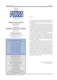
Fig. 1. Crank and rocker piston assembly (courtesy of the author of the<br />
design)<br />
Rys. 1. Wahaczowy mechanizm korbowy (za zgodą autora patentu)<br />
2) whose axis of rotation O does not overlap with the axis of<br />
rotation of the crankshaft. The two outstanding arms of the<br />
rocker of length R t<br />
, acting as crank arms (fitted with pivots<br />
at the ends (7)) are coupled with a pair of pistons (11). The<br />
connector (8), which can be very short, acts as a connecting<br />
rod. At a constant length of l t<br />
the rotation of the rocker forces<br />
the reciprocating motion of the pistons. The pistons forming a<br />
pair can be connected into a single monolith as shown in Fig.<br />
1, or remain separate as in Fig. 2. In the second case, another<br />
connecting rod is necessary (connector 8) so that the pistons<br />
can move separately. Their motion, however, is harmonized<br />
through a drive with a common journal (7).<br />
The rocker is rigid and during a rotation by angle b all<br />
its arms rotate at the same time. When l > R, during the<br />
rotary motion of the crank of arm r arms R and R t<br />
move in<br />
the rocking-reciprocating manner and this movement forces<br />
the reciprocation of the pistons. Because of the kinematic<br />
pairs that are a part of the design during these movements<br />
connector lt also moves in the rocking reciprocating manner<br />
by angle g.<br />
The aim of this paper is to shed light on the properties<br />
of the mechanism. That is why the author decided that the<br />
qualitative analysis would be sufficient. To this end a comparative<br />
analysis has been used. A reference for the rocker<br />
piston assembly, hereinafter referred to as mechanism W is<br />
the commonly known regular piston assembly hereinafter referred<br />
to as mechanism K, constructed from a rotating crank<br />
of the crankshaft and a connecting rod joining the crankshaft<br />
journal with the piston. The author assumed that a reliable<br />
evaluation will be obtained when limiting the topic to the<br />
complexity of the design, changes in the piston kinematics,<br />
heat losses to the cooling system, indicated work, changes<br />
in the course of the torque, balancing of the reciprocating<br />
<strong>COMBUSTION</strong> <strong>ENGINES</strong>, No. 1/2013 (152)<br />
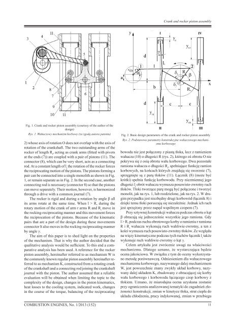
Fig. 2. Basic design parameters of the crank and rocker piston assembly<br />
Rys. 2. Podstawowe parametry konstrukcyjne wahaczowego mechanizmu<br />
korbowego<br />
bowodu nie jest połączony z piastą tłoka, lecz z ramieniem<br />
wahacza (10) o długości R (rys. 2), którego oś obrotu O nie<br />
pokrywa się z osią obrotu wału korbowego. Dwa pozostałe<br />
ramiona wahacza o długości R t<br />
, spełniające funkcję ramion<br />
korbowych, na końcach których znajdują się sworznie (7),<br />
sprzęgnięte są z parą tłoków (11). Łącznik (8) (może być<br />
krótki) spełnia funkcję korbowodu. Przy niezmiennej jego<br />
długości l t<br />
obrót wahacza wymusza posuwisto-zwrotny ruch<br />
tłoków. Tłoki tworzące parę mogą być połączone i tworzyć<br />
monolit, jak na rys. 1, lub rozdzielone, jak na rys. 2. W drugim<br />
przypadku jest niezbędny drugi korbowód (łącznik 8) i<br />
dzięki temu tłoki poruszają się niezależnie. Jednak ich ruch<br />
jest sprzężony przez napęd wspólnym czopem (7).<br />
Przy sztywnej konstrukcji wahacza podczas obrotu o kąt<br />
b obracają się jednocześnie wszystkie jego ramiona. Gdy<br />
l > R, podczas ruchu obrotowego korby o ramieniu r ramiona<br />
R i R t<br />
wahacza wykonują ruch wahliwie-zwrotny, a ten z<br />
kolei wymusza ruch posuwisto-zwrotny tłoków. Ze względu<br />
na więzy kinematyczne podczas tych ruchów łącznik l t<br />
także<br />
wykonuje ruch wahliwie-zwrotny o kąt g.<br />
Celem artykułu jest zwrócenie uwagi na właściwości<br />
mechanizmu. Dlatego uznano, że wystarczająca będzie<br />
ocena jakościowa. W związku z tym do oceny wykorzystano<br />
metodę porównawczą. Odniesieniem dla wahaczowego<br />
mechanizmu korbowego, nazywanego dalej mechanizmem<br />
W, jest powszechnie znany zwykły układ korbowy, nazywany<br />
dalej układem K, zbudowany z obracającej się korby<br />
wału korbowego i korbowodu łączącego czop korbowy z<br />
tłokiem. Uznano, że miarodajna ocena uzyskana zostanie<br />
przy ograniczeniu analizowanej tematyki do zagadnień złożoności<br />
konstrukcji, zmian w kinetyce tłoka, strat ciepła do<br />
układu chłodzenia, pracy indykowanej, zmian w przebiegu<br />
11