
You also want an ePaper? Increase the reach of your titles
YUMPU automatically turns print PDFs into web optimized ePapers that Google loves.
Wahaczowy mechanizm korbowo-tłokowy<br />
From the schematics in Fig. 7 the following results:<br />
. Using the properties of trigonometrical<br />
functions, this expression can be written:<br />
. In order to define functions<br />
cos c and sin c we can use the coordinates of points 1 and<br />
2: , and . Upon substituting<br />
and conversions we obtain:<br />
(11)<br />
(12)<br />
Force N of the piston on the cylinder liner<br />
, a . Po podstawieniu i przekształceniach<br />
otrzymuje się wzór (11) i (12).<br />
Since the rocker does not make a full revolution an invaluable<br />
feature of mechanism W is the possibility of such<br />
selection of the design parameters<br />
and such connection of the piston<br />
with the rocker arm as to make the<br />
angle between arm R t<br />
and the connecting<br />
rod l t<br />
(Fig. 6) as close to<br />
straight angle as possible and the<br />
changes in angle g symmetrically<br />
distributed along the cylinder axis.<br />
The angular path b that the rocker<br />
arm covers between the top and<br />
bottom piston positions depends<br />
on radius R t<br />
. Taking (8) and (9)<br />
into account, we can confirm that<br />
at a set value of r the changes of<br />
the value of angle b and angle z<br />
decrease as R t<br />
grows during the<br />
rotation of the crankshaft. Hence<br />
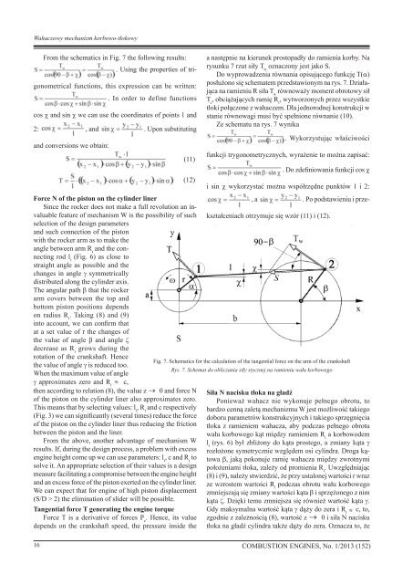
Fig. 7. Schematics for the calculation of the tangential force on the arm of the crankshaft<br />
the value of angle g is reduced too.<br />
Rys. 7. Schemat do obliczania siły stycznej na ramieniu wału korbowego<br />
When the maximum value of angle<br />
g approximates zero and R t<br />
c,<br />
then according to relation (8), the value z 0 and force N<br />
of the piston on the cylinder liner also approximates zero.<br />
This means that by selecting values: l t<br />
, R t<br />
and c respectively<br />
(Fig. 3) we can significantly (several times) reduce the force<br />
of the piston on the cylinder liner thus reducing the friction<br />
between the piston and the liner.<br />
From the above, another advantage of mechanism W<br />
results. If, during the design process, a problem with excess<br />
engine height come up we can use parameters: l t<br />
, c and R t<br />
to<br />
solve it. An appropriate selection of their values is a design<br />
measure facilitating a compromise between the engine height<br />
and an excess force of the piston exerted on the cylinder liner.<br />
We can expect that for engine of high piston displacement<br />
(S/D > 2) the elimination of slider will be possible.<br />
Tangential force T generating the engine torque<br />
Force T is a derivative of forces P c<br />
. Hence, its value<br />
depends on the crankshaft speed, the pressure inside the<br />
a następnie na kierunek prostopadły do ramienia korby. Na<br />
rysunku 7 rzut siły T w<br />
oznaczony jest jako S.<br />
Do wyprowadzenia równania opisującego funkcję T(a)<br />
posłużono się schematem przedstawionym na rys. 7. Działająca<br />
na ramieniu R siła T w<br />
równoważy moment obrotowy sił<br />
T c<br />
, obciążających ramię R t<br />
, wytworzonych przez wszystkie<br />
tłoki połączone z wahaczem. Dla jednorodnej konstrukcji w<br />
stanie równowagi musi być spełnione równanie (10).<br />
Ze schematu na rys. 7 wynika<br />
. Wykorzystując właściwości<br />
funkcji trygonometrycznych, wyrażenie to można zapisać:<br />
. Do zdefiniowania funkcji cos c<br />
i sin c wykorzystać można współrzędne punktów 1 i 2:<br />
Siła N nacisku tłoka na gładź<br />
Ponieważ wahacz nie wykonuje pełnego obrotu, to<br />
bardzo cenną zaletą mechanizmu W jest możliwość takiego<br />
doboru parametrów konstrukcyjnych i takiego sprzęgnięcia<br />
tłoka z ramieniem wahacza, aby podczas pełnego obrotu<br />
wału korbowego kąt między ramieniem R t<br />
a korbowodem<br />
l t<br />
(rys. 6) był zbliżony do kąta prostego, a zmiany kąta g<br />
rozłożone symetrycznie względem osi cylindra. Droga kątowa<br />
b, jaką pokonuje ramię wahacza między zwrotnymi<br />
położeniami tłoka, zależy od promienia R t<br />
. Uwzględniając<br />
(8) i (9), należy stwierdzić, że przy ustalonej wartości r wraz<br />
ze wzrostem wartości R t<br />
podczas obrotu wału korbowego<br />
zmniejszają się zmiany wartości kąta b i sprzężonego z nim<br />
kąta z. Dzięki temu zmniejsza się również wartość kąta g.<br />
Gdy maksymalna wartość kąta g dąży do zera i R t<br />
c, to,<br />
zgodnie z zależnością (8), wartość z 0 i siła N nacisku<br />
tłoka na gładź cylindra także dąży do zera. Oznacza to, że<br />
16 <strong>COMBUSTION</strong> <strong>ENGINES</strong>, No. 1/2013 (152)