
Create successful ePaper yourself
Turn your PDF publications into a flip-book with our unique Google optimized e-Paper software.
Crank and rocker piston assembly<br />
essence is the design of the rocker. The idea of one of such<br />
designs is presented in the schematics in Fig. 16 [2]. The arm<br />
(2) connecting the rocker (1) with the crankshaft does not<br />
form a monolith with the rest of the arms of the rocker.<br />
Thanks to this we achieve an additional degree of freedom.<br />
Despite the rotational movement around the axis of<br />
the toothed shaft (3) the arm can also make a reciprocating<br />
movement in guide P of the rocker, thus working as a slider.<br />
The reciprocating movement of arm (2) along the guide<br />
is generated by a fragment of rack L made in the arm and<br />
coupled with the toothed shaft. The axis of the toothed shaft<br />
is also the axis of rotation of the rocker (performs a movement<br />
by angle b, Fig. 7). If during the swing an additional<br />
angular displacement da of the toothed shaft is done then<br />
as a result of the coupling with the rack, the displacement of<br />
the rocker arm (by dx) will take place in the guide as well.<br />
The value of R will change to R + dx and a change in the<br />
position will occur in TDC.<br />
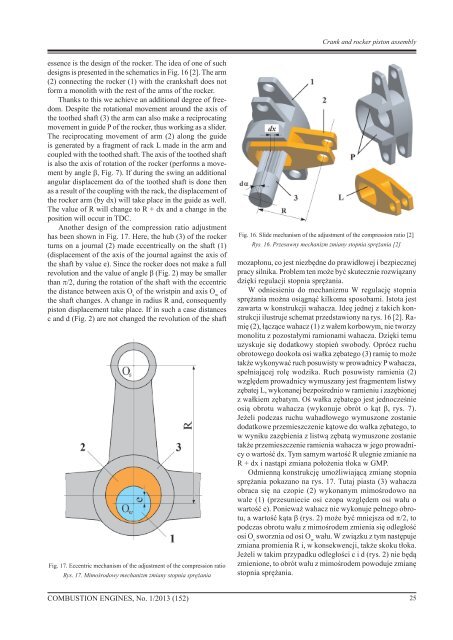
Another design of the compression ratio adjustment<br />
has been shown in Fig. 17. Here, the hub (3) of the rocker<br />
turns on a journal (2) made eccentrically on the shaft (1)<br />
(displacement of the axis of the journal against the axis of<br />
the shaft by value e). Since the rocker does not make a full<br />
revolution and the value of angle b (Fig. 2) may be smaller<br />
than p/2, during the rotation of the shaft with the eccentric<br />
the distance between axis O s<br />
of the wristpin and axis O w<br />
of<br />
the shaft changes. A change in radius R and, consequently<br />
piston displacement take place. If in such a case distances<br />
c and d (Fig. 2) are not changed the revolution of the shaft<br />
Fig. 17. Eccentric mechanism of the adjustment of the compression ratio<br />
Rys. 17. Mimośrodowy mechanizm zmiany stopnia sprężania<br />
Fig. 16. Slide mechanism of the adjustment of the compression ratio [2]<br />
Rys. 16. Przesuwny mechanizm zmiany stopnia sprężania [2]<br />
mozapłonu, co jest niezbędne do prawidłowej i bezpiecznej<br />
pracy silnika. Problem ten może być skutecznie rozwiązany<br />
dzięki regulacji stopnia sprężania.<br />
W odniesieniu do mechanizmu W regulację stopnia<br />
sprężania można osiągnąć kilkoma sposobami. Istota jest<br />
zawarta w konstrukcji wahacza. Ideę jednej z takich konstrukcji<br />
ilustruje schemat przedstawiony na rys. 16 [2]. Ramię<br />
(2), łączące wahacz (1) z wałem korbowym, nie tworzy<br />
monolitu z pozostałymi ramionami wahacza. Dzięki temu<br />
uzyskuje się dodatkowy stopień swobody. Oprócz ruchu<br />
obrotowego dookoła osi wałka zębatego (3) ramię to może<br />
także wykonywać ruch posuwisty w prowadnicy P wahacza,<br />
spełniającej rolę wodzika. Ruch posuwisty ramienia (2)<br />
względem prowadnicy wymuszany jest fragmentem listwy<br />
zębatej L, wykonanej bezpośrednio w ramieniu i zazębionej<br />
z wałkiem zębatym. Oś wałka zębatego jest jednocześnie<br />
osią obrotu wahacza (wykonuje obrót o kąt b, rys. 7).<br />
Jeżeli podczas ruchu wahadłowego wymuszone zostanie<br />
dodatkowe przemieszczenie kątowe da wałka zębatego, to<br />
w wyniku zazębienia z listwą zębatą wymuszone zostanie<br />
także przemieszczenie ramienia wahacza w jego prowadnicy<br />
o wartość dx. Tym samym wartość R ulegnie zmianie na<br />
R + dx i nastąpi zmiana położenia tłoka w GMP.<br />
Odmienną konstrukcję umożliwiającą zmianę stopnia<br />
sprężania pokazano na rys. 17. Tutaj piasta (3) wahacza<br />
obraca się na czopie (2) wykonanym mimośrodowo na<br />
wale (1) (przesuniecie osi czopa względem osi wału o<br />
wartość e). Ponieważ wahacz nie wykonuje pełnego obrotu,<br />
a wartość kąta b (rys. 2) może być mniejsza od p/2, to<br />
podczas obrotu wału z mimośrodem zmienia się odległość<br />
osi O s<br />
sworznia od osi O w<br />
wału. W związku z tym następuje<br />
zmiana promienia R i, w konsekwencji, także skoku tłoka.<br />
Jeżeli w takim przypadku odległości c i d (rys. 2) nie będą<br />
zmienione, to obrót wału z mimośrodem powoduje zmianę<br />
stopnia sprężania.<br />
<strong>COMBUSTION</strong> <strong>ENGINES</strong>, No. 1/2013 (152)<br />
25