
Create successful ePaper yourself
Turn your PDF publications into a flip-book with our unique Google optimized e-Paper software.
Optical single cylinder engines in engine research and development<br />
gasket rings must not contact the glass liner, they<br />
are positioned on the lower end of the piston crown<br />
and glide on the metal liner part only. This implies a<br />
noticeable reduction of engine compression ratio.<br />
6. Compression ratio considerations<br />
Piston rings in an OSCE are most often on<br />
lower positions than in a normal piston. This low<br />
ring position together with a typical piston to liner<br />
clearance of 0.5 mm adds to the dead volume of the<br />
combustion chamber and reduces compression ratio<br />
between 1 and 3 units.<br />
In an SI engine, such CR reduction is most often<br />
acceptable as the primary aim of an OSCE is the<br />
analysis of mixture formation during intake and<br />
compression stroke. In a Diesel OSCE, however,<br />
such CR reduction has noticeable influence on ignition<br />
delay and combustion. Here it is most advisable<br />
to compensate smaller CR with intake air heating<br />
and boosting to achieve relevant evaporation, ignition<br />
and combustion conditions.<br />
7. A single cylinder test bed system<br />
Operating an OSCE is best accomplished with a<br />
modular test bed platform system comprising modules<br />
as shown in the schematic of Fig. 4. The core<br />
parts of such system are the engine and dyno, but productive<br />
test operation most often requires a number of peripheral<br />
components for:<br />
– engine conditioning,<br />
– media supply and conditioning,<br />
– control of dyno, engine and measurement modules,<br />
– fuel injection system,<br />
– safety actuators and control software,<br />
– measurement modules,<br />
– user interfaces to access all signals and actuators.<br />
Organizing the complexity of such installations is best<br />
accomplished in a modular platform architecture with well<br />
defined interfaces between required system modules.<br />
8. An OSCE measurement example<br />
The screenshots in Fig. 5 give a typical example for<br />
operating an OSCE, here with a GDI head configuration.<br />
Crank angle resolved operating signals are recorded continuously<br />
together with image sequences of in-cylinder events.<br />
The total group of fired cycles together with motored cycles<br />
before and after fuel injection is available for analysis. Cycle<br />
specific engine operation data, camera control signals and<br />
also emissions signals are accessible. As the OSCE must only<br />
be fired for a limited number of cycles, engine operation,<br />
synchronization with actuators and measurement devices and<br />
control of operating limits is performed within the measurement<br />
control system.<br />
9. OSCE data evaluation examples<br />
9.1. GDI sprays and mixture formation<br />
Understanding fuel injection and mixture formation<br />
processes in GDI engines is of central importance for the<br />
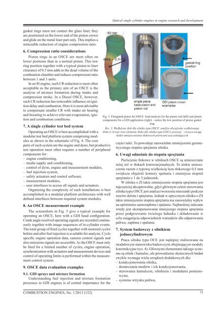
Fig. 3. Elongated piston for OSCE: load analysis for the piston rod (left) and piston<br />
components for a GDI application (right) – notice the low position of piston gasket<br />
ring<br />
Rys. 3. Wydłużony tłok dla silnika typu OSCE: analiza obciążenia wydłużonego<br />
tłoka (z lewej) oraz elementy tłoka dla silnika typu GDI (z prawej) – zwraca uwagę<br />
niskie umiejscowienie tłokowych pierścieni uszczelniających<br />
części tulei. To powoduje zauważalne zmniejszenie geometrycznego<br />
stopnia sprężania silnika.<br />
6. Uwagi odnośnie do stopnia sprężania<br />
Pierścienie tłokowe w silnikach OSCE są umieszczane<br />
niżej niż w tłokach konwencjonalnych. To niskie umieszczenie<br />
razem z typową wielkością luzu tłokowego 0,5 mm<br />
zwiększa objętość komory spalania i zmniejsza stopień<br />
sprężania o 1 do 3 jednostek.<br />
W silniku o ZI takie zmniejszenie stopnia sprężania jest<br />
najczęściej akceptowalne, gdyż głównym celem stosowania<br />
silnika typu OSCE jest analiza tworzenia mieszanki podczas<br />
suwów dolotu i sprężania. Jednak w optycznym silniku o ZS<br />
takie zmniejszenie stopnia sprężania ma zauważalny wpływ<br />
na opóźnienie samozapłonu i spalanie. Najbardziej zalecane<br />
wtedy jest skompensowanie mniejszego stopnia sprężania<br />
przez podgrzewanie świeżego ładunku i doładowanie w<br />
celu osiągnięcia odpowiednich warunków dla odparowania<br />
paliwa, zapłonu i spalania.<br />
7. System badawczy z silnikiem<br />
jednocylindrowym<br />
Praca silnika typu OCE jest najlepiej realizowana na<br />
modułowym stanowisku badawczym obejmującym moduły<br />
konstrukcyjne (rys. 4). Głównymi elementami takiego systemu<br />
są silnik i hamulec, ale prowadzenie skutecznych badań<br />
zwykle wymaga wielu urządzeń dodatkowych dla:<br />
– kondycjonowania silnika,<br />
– dostarczania mediów i ich kondycjonowania,<br />
– sterowania hamulcem, silnikiem i modułami pomiarowymi,<br />
– systemu wtrysku paliwa,<br />
<strong>COMBUSTION</strong> <strong>ENGINES</strong>, No. 1/2013 (152)<br />
75