
Create successful ePaper yourself
Turn your PDF publications into a flip-book with our unique Google optimized e-Paper software.
Rozwój aparatury i metod badawczych emisji związków szkodliwych spalin samochodowych...<br />
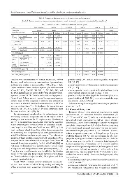
Table 1. Component detection ranges of the exhaust gas analysis system<br />
Tabela 1. Zakresy pomiarowe zastosowanych analizatorów spalin w systemie pomiarowym emisji związków szkodliwych<br />
MEXA 7400 HTRLE + MEXA 7500 DEGR Emissions Analysis System<br />
Line Low Emission Diluted CO2Tracer PreCat PostCat EGR<br />
Component<br />
(detection principle)<br />
CO<br />
(NDIR)<br />
Range Range Range Range Range Range<br />
lowest highest lowest highest lowest highest lowest highest lowest highest lowest highest<br />
Low [ppm]<br />
0-50 0-2500<br />
0-50 0-5000 0-50 0-5000<br />
0-10 0-500<br />
– –<br />
High [%] 0-0.5 0-12 0-0.5 0-12 0-0.5 0-12<br />
– –<br />
CO 2<br />
(NDIR) [%] 0-0.5 0-20 0-0.5 0-20 0-0.5 0-20 0-0.5 0-20 0-0.5 0-20 0-0.5 0-20<br />
O 2<br />
(MPA) [%] – – – – – – 0-1 0-25 – – – –<br />
NO x<br />
(CLD)<br />
Low [ppm] 0-1 0-50 0-10 0-500<br />
High [ppm] 0-100 0-1000 0-1000 0-10000<br />
– – 0-10 0-10000 0-10 0-10000 – –<br />
NO (CLD) [ppm] – – – – – – 0-10 0-10000 0-10 0-10000 – –<br />
THC<br />
Gasoline<br />
(FID)<br />
THC<br />
Diesel<br />
(HFID)<br />
Low [ppmC1]<br />
0-10 0-500<br />
High [ppmC1]<br />
0-1 0-50<br />
0-1000 0-50000<br />
Low [ppmC1]<br />
0-10 0-500<br />
High [ppmC1]<br />
– –<br />
0-1000 0-50000<br />
– – – – – – – –<br />
– – – – – – – –<br />
CH4 (GC-FID) [ppm C1] 0-1 0-500 – – – – – – – – – –<br />
THC (HFID) [ppmC1] – – – – – – 0-10 0-50000 0-10 0-50000 – –<br />
THC / CH 4<br />
(HFID) [ppmC1] – – – – – – 0-10 0-50000 0-10 0-50000 – –<br />
simultaneous measurement of carbon monoxide, carbon<br />
dioxide, total hydrocarbons, non-methane hydrocarbons,<br />
methane and oxides of nitrogen (NO+NO 2<br />
), (Fig. 5, Tab.<br />
1) and another exhaust analyser system (for measurement<br />
of raw HC, CH 4<br />
, NMHC, CO, CO 2<br />
, O 2<br />
, NO, NO 2<br />
, NO x<br />
and<br />
the EGR percentage) all controlled by the laboratory management<br />
system VETS (Vehicle emissions testing system).<br />
Figure 6 and 7 show an overview of the upgraded system.<br />
Sample bags for the sampling of ambient and exhaust air<br />
are housed in a heated, insulated unit maintained at 35 °C to<br />
prevent condensation (Fig. 8). Analysers for measuring raw<br />
emissions of THC, CH 4<br />
and NO x<br />
are sited separately from<br />
the main analyser racks (Fig. 9).<br />
Two independent sampling lines for exhaust gases were<br />
previously installed: a separate line for SI engines with a<br />
mixing tee; and a second for CI engines with a dilution tunnel<br />
[1]. In the recent upgrade, heated lines for the sampling<br />
of raw exhaust gases are installed in the chamber, of sufficient<br />
length to test all types of vehicles up to 3500 kg, both<br />
front- and rear-wheel drive. One of the design criteria for<br />
the laboratory was the possibility of adding extra modules<br />
to fulfil additional analytic requirements. The laboratory<br />
has already been used in conjunction with a standalone NH 3<br />
analyser for the ammonia emissions analysis from CI and SI<br />
automobile engines (especially fuelled with CNG) [14], as<br />
well as an FTIR analyser (for quantification of a wide range<br />
of regulated and unregulated exhaust gas compounds) [15].<br />
A particle size classifier could also be added to the dilution<br />
tunnel for research and development purposes which focus<br />
on Diesel and direct injection (DI) SI engines and their<br />
respective particulate traps.<br />
VETS7000NT control software maintains the analysers<br />
and their various activities during testing and analysis<br />
of bag emissions, such as zeroing, spanning, etc (Fig. 10).<br />
– pomiary emisji CO 2<br />
i zużycia paliwa zgodnie z przepisami<br />
UE [12, 13]<br />
– pomiary nieprzeźroczystości spalin zgodnie z przepisami<br />
UE [11, 12]<br />
– masowy pomiar emisji cząstek stałych i określanie liczby<br />
emitowanych cząstek stałych według [4, 13]<br />
– pomiary związków nieobjętych limitami emisji w przepisach,<br />
takich jak N 2<br />
O, NH 3<br />
przy użyciu dodatkowego<br />
analizatora (AVL AMAi60).<br />
Schemat zmodyfikowanego laboratorium jest przedstawiony<br />
na rys. 2.<br />
2.2. Komora klimatyczna<br />
Komora klimatyczna stanowi podstawową część<br />
laboratorium. W szerokim zakresie temperatur (od<br />
–35 °C do +60 °C, rys. 3) bada się w niej emisję związków<br />
szkodliwych spalin, zużycie paliwa i osiągi silnika i<br />
samochodu. Zakres ten wykracza poza obecne wymagania<br />
przepisów dotyczących emisji, ale jest bardzo przydatny<br />
w prowadzonych pracach rozwojowych nad nowymi i<br />
modernizowanymi pojazdami i ich silnikami. Szeroki<br />
zakres temperatur otoczenia, w których mogą być prowadzone<br />
badania (95 °C) jest odpowiedzą na obecne i<br />
przyszłe wymagania badawcze producentów silników,<br />
olejów smarujących, paliw i reaktorów katalitycznych.<br />
Komora pomiarowa wyposażona jest w systemy kontroli<br />
temperatury i wilgotności powietrza, które dają możliwość<br />
utrzymywania żądanej temperatury i wilgotności z dużą<br />
dokładnością. Podczas pracy komory (włącznie z prowadzeniem<br />
testów emisji i badaniami osiągów pojazdu),<br />
jest możliwa:<br />
– kontrola temperatury powietrza w komorze w zakresie od<br />
–35 °C do +60 °C<br />
– dokładność ustawień (tolerancja temperatury): ±1,0 °C<br />
(w warunkach statycznych, bez wydzielania ciepła);<br />
34 <strong>COMBUSTION</strong> <strong>ENGINES</strong>, No. 1/2013 (152)