Opperations Manual 2075 - Alberta Oil Tool
Opperations Manual 2075 - Alberta Oil Tool
Opperations Manual 2075 - Alberta Oil Tool

Create successful ePaper yourself
Turn your PDF publications into a flip-book with our unique Google optimized e-Paper software.
Operation and Maintenance<br />
Series 2-<strong>2075</strong> – Control Valve<br />
SPECIFICATIONS<br />
Body Size:<br />
Body Style:<br />
Body End Connection:<br />
Body Closure Type:<br />
Max. Working Pressure:<br />
2.00 Inch<br />
Angle or Globe<br />
Threaded, 2.00 NPT<br />
Bolted<br />
600 PSIG at 1000 F<br />
Materials of Construction: See Table 1<br />
Temperature Limits:<br />
Valve Weights:<br />
-20 degrees F to 1800 F<br />
See Table II<br />
Seat Leakage Class: Class VI, per ANSI B16.104<br />
Orifice Diameter:<br />
Stem Travel:<br />
Actuator Type:<br />
1.25 Inch<br />
0.50 Inch<br />
Pneumatic<br />
(Diaphragm/Spring Return)<br />
(Adjustable or Non – Adjustable<br />
Spring)<br />
Actuator Size<br />
No. 9 (35 Sq. In.)<br />
No. 12 (70 Sq. In.)<br />
Actuator Supply Connection: 1/4 - 18 NPT<br />
Actuator Action:<br />
Reverse (Normally Closed)<br />
Direct (Normally Open)<br />
*Maximum Recommended Supply Pressure 35 PSI<br />
GENERAL DESCRIPTION<br />
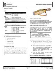
The Norriseal Series <strong>2075</strong> is a single-seated, pneumatically<br />
operated control valve designed for low to moderate<br />
pressures in either liquid or gas applications. Valve trim is<br />
of the quick opening type, and the soft-seated valve plug<br />
provides leak-free shutoff. Fluid flow may be directed either<br />
over or under the valve seat. The Series <strong>2075</strong> may be<br />
furnished with either a 35 or 70 square inch actuator.<br />
Operating mode may be either reverse (normally closed) or<br />
direct (normally open). With optional materials of<br />
construction, the Series <strong>2075</strong> complies with NACE material<br />
specification MR-01-75.<br />
Table 1<br />
Materials of Construction<br />
VALVE BODY COMPONENTS<br />
ITEM DESCRIPTION STD MAT'L NACE MAT'L<br />
BODY<br />
PACKING PLUG<br />
PACKING PLUG CAP<br />
VALVE SEAT<br />
VALVE CAGE<br />
VALVE STEM<br />
PLUG DISC<br />
PLUG RETAINER<br />
COTTER PIN<br />
CASTLE NUT<br />
STEM GUIDE<br />
PLUG INSERT<br />
O-RINGS<br />
BACK-UP RINGS<br />
A395 D.I.<br />
1215 CSTL<br />
1215 CSTL<br />
303 SST<br />
304 SST<br />
303 SST<br />
303 SST<br />
303 SST<br />
18-8 SST<br />
18-8 SST<br />
KYNAR+<br />
TEFLON<br />
VITON<br />
TFE<br />
A395 D.I.<br />
1018 CSTL<br />
1018 CSTL<br />
316 SST<br />
304 SST<br />
316 SST<br />
316 SST<br />
316 SST<br />
18-8 SST<br />
18-8 SST<br />
KYNAR+<br />
VITON*<br />
VITON*<br />
TFE<br />
ACTUATOR COMPONENTS<br />
ITEM DESCRIPTION<br />
MATERIAL<br />
DIAPHRAGM HOUSINGS<br />
SPRINGS<br />
DIAPHRAGM PLATE<br />
SPRING RETAINER<br />
DIAPHRAGM<br />
CAP SCREWS AND NUTS<br />
ADJUSTING SCREW<br />
JAM NUT<br />
BODY/ACTUATOR BOLTING<br />
LOCK WASHERS<br />
ACTUATOR SEAL NUTS<br />
ACTUATOR GASKET<br />
POSITION INDICATOR<br />
CSTL<br />
CSTL<br />
CSTL<br />
CSTL<br />
BUNA-N<br />
CSTL PLTD<br />
CSTL PLTD<br />
CSTL PLTD<br />
A193 GR. B8M (316 SST)<br />
CSTL PLTD<br />
CSTL/NYLON<br />
ASB/NBR<br />
SST/DELRIN<br />
*Registered U.S. Patent Office F/Dupont's Fluorelastomers<br />
+Registered Trademark Pennwalt Corporation<br />
INSTALLATION & START-UP<br />
CAUTION:<br />
Maximum working pressure for the Series <strong>2075</strong> is 600<br />
PSIG. If system pressure is capable of exceeding 600<br />
PSIG, a relief valve or other over-pressure protection<br />
should be installed.<br />
1. Prior to installation, remove thread protectors from body<br />
end connections, and inspect valve for any shipping<br />
damage.<br />
2. Flow through valve may be in either direction, as<br />
appropriate for the particular application. If valve has a<br />
globe style body, the upper and lower body ports may be<br />
identified from bridge symbol on body exterior.<br />
NOTE: If flow is directed in lower body port, shutoff<br />
differential pressure will be under valve plug, and<br />
tending to open.<br />
See Table III for Maximum Differentials<br />
Maintained by: Sales Department Page 1 of 4 Doc. Name:OpMain2-<strong>2075</strong>.doc<br />
Approved by: Quality Department Rev.: C Date: 12-Feb-04
Operation and Maintenance<br />
TABLE II<br />
Valve Weights (approximate)<br />
(Weights are in lbs.)<br />
ACTUATOR SIZE AND TYPE<br />
NO. 9 (35 SQ. IN.) NO. 12 (70 SQ. IN.)<br />
BODY STYLE<br />
REVERSE DIRECT REVERSE DIRECT<br />
GLOBE 24 25 32 34<br />
ANGLE 23 24 31 33<br />
TABLE III<br />
Maximum Differential Pressures<br />
NO. 9 & NO.12 Adjustable Actuator<br />
NO. 9 AND NO. 12 ADJUSTABLE ACTUATOR<br />
DIAPHRAGM FLOW UNDER SEAT FLOW OVER SEAT<br />
SUPPLY NO. 9 NO. 12 NO. 9 NO. 12<br />
PRESSURES REV DIR REV DIR REV DIR REV DIR<br />
18 270 170 430 275 300 300 600 600<br />
24 300 300 600 600 300 300 600 600<br />
NO. 9 NON-ADJUSTABLE ACTUATOR<br />
DIAPHRAGM<br />
SUPPLY<br />
PRESSURES<br />
ACTUATOR<br />
TYPE<br />
FLOW OVER SEAT<br />
FLOW<br />
OVER SEAT<br />
REV DIR REV DIR<br />
12 9BA2 60 300 300 300<br />
15 9BA2 75 300 300 300<br />
24 9BA4 140 --- 300 ---<br />
32 9BA4 180 --- 300 ---<br />
3. Before installing valve, examine male (pipe) threads to<br />
be sure they are clean and free of damage. To reduce<br />
thread friction and assure a tight joint, apply TFE tape or<br />
other lubricant to the male threads. Before final<br />
tightening, be sure that body and pipe threads are<br />
properly engaged.<br />
4. Remove plastic thread protector plug from actuator<br />
supply connection. Connect actuator supply line to 1/4 -<br />
18 NPT connection in diaphragm housing.<br />
5. Check for proper valve operation by cycling actuator<br />
several times and observing position indicator. Indicator<br />
movement corresponds to valve stem travel and should<br />
be 0.50inch.<br />
VALVE MAINTENANCE<br />
Series 2-<strong>2075</strong> – Control Valve<br />
1. Disassembly -Before disassembling valve, complete the<br />
following steps:<br />
a) Isolate valve from the process.<br />
b) Release process pressure captured in<br />
pipeline.<br />
c) Vent actuator supply pressure.<br />
d) If reverse actuator, relieve actuator spring<br />
compression.<br />
Remove (2) 3/8-16 UNC heavy hex nuts securing<br />
actuator to valve body. Lift actuator straight up and out<br />
of body. Valve stem and plug, and packing plug<br />
assembly, will also come out of body and remain<br />
attached to actuator. Seat and cage will remain in body.<br />
2. Inspection Remove seat, cage, and seat o-ring from body<br />
and inspect for damage and wear. Inspect body interior<br />
for evidence of corrosion, erosion, or other damage. O-<br />
ring seal surfaces at bottom of seat recess and inside top<br />
bore should be smooth and free of damage for proper<br />
sealing.<br />
Inspect exposed portion of plug insert for damage that<br />
could impair tight shutoff. Inspect o-ring in packing plug<br />
groove for damage. Replace if necessary.<br />
NOTE: The packing plug o-ring is the primary seal<br />
which prevents external leakage of process fluid from<br />
valve body.<br />
To inspect valve stem and stem seal o-rings, first remove<br />
cotter pin at bottom of stem. Next, remove 5/16-24 hex<br />
castle nut securing plug to stem. Slide plug retainer,<br />
insert and disc from end of stem. Remove packing plug<br />
and stem guide by sliding off end of stem. Packing plug<br />
cap may now be removed in a similar manner. Valve<br />
stem should now be carefully inspected for any wear or<br />
damage that would prevent effective sealing against stem<br />
o-ring seals. If stem is judged to be in serviceable<br />
condition and not in need of replacement, proceed to<br />
"Reassembly".<br />
Replacement of valve stem requires disassembly of<br />
actuator. First, remove(12) 3/8 -16 UNC hex cap screws<br />
securing upper and lower diaphragm housings. Remove<br />
(2) 5/16-`24UNF hex jam nuts securing diaphragm plate<br />
and diaphragm to upper end of stem. If actuator is the<br />
direct-acting (normally open) type, these parts are<br />
secured by upper actuator stem, instead of jam nuts.<br />
Maintained by: Sales Department Page 2 of 4 Doc. Name: OpMain2-<strong>2075</strong>.doc<br />
Approved by: Quality Department Rev.: C Date:12-Feb-04
Operation and Maintenance<br />
Series 2-<strong>2075</strong> – Control Valve<br />
INSTALLATION OF VALVE STEM:<br />
CAUTION:<br />
Before reassembling valve stem with diaphragm plate,<br />
carefully observe the length of threaded portion at each<br />
end of stem. The end having the longer threaded portion<br />
(0.88 inch, vs. 0.50 inch) is the upper end, and must be<br />
secured to the actuator components. The shorter (0.50<br />
inch) threaded length is the bottom end, and must be<br />
assembled with the valve plug.<br />
After selecting a new valve stem, reinstall bearing<br />
washers, diaphragm, and diaphragm plate in their<br />
respective positions on upper end of stem. Replace jam<br />
nuts or upper actuator stem, then reassemble remaining<br />
actuator components. Inspect flat gasket surrounding<br />
center hole at bottom of lower diaphragm housing.<br />
Replace gasket if necessary.<br />
3. Reassembly - Reinstall packing plug cap so that center<br />
hub engages hole in lower diaphragm housing (o-ring<br />
recess will be facing bottom of stem). Install TFE<br />
backup ring, o-ring and stem guide. Stem guide will<br />
push backup ring and o-ring into their proper positions in<br />
cap. Install remaining TFE backup ring and o-ring in<br />
packing plug recess. Carefully slide packing plug over<br />
end of stem, and slide into position until packing plug<br />
touches packing plug cap.<br />
Install plug disc on stem, with o-ring groove facing<br />
bottom of stem. Install disc o-ring, plug insert and<br />
retainer.<br />
NOTE: Plug insert is designed for a snug fit on stem.<br />
Install hex castle nut to secure plug components. Install<br />
cotter pin through hole near bottom of stem. Install seat o-<br />
ring and valve seat in body seat recess.<br />
NOTE: Observe correct orientation of valve seat. 45 degree<br />
chamber must be facing downward to properly engage seat<br />
o-ring.<br />
Install valve cage on top of seat. Cage is reversible and may<br />
be installed in either direction.<br />
To complete the re-assembly, position actuator directly<br />
above body. Lover into position, carefully inserting packing<br />
plug into body bore, while actuator studs engage holes in<br />
body lugs. Install hex nuts on actuator studs, and run nuts<br />
up finger-tight against body lugs.<br />
CAUTION:<br />
It is important to tighten each nut on each stud in small<br />
increments, while alternating from one stud to the other.<br />
This will assure proper alignment and prevent actuator<br />
from becoming tilted. Final torque value on each stud<br />
should be 18-20 ft-lbs.<br />
Valve re-assembly is not complete. Check for proper<br />
operation by applying instrument air to actuator and<br />
observing position indicator movement.<br />
TROUBLE SYMPTOMS PROBABLE CAUSE CORRECTIVE ACTION<br />
(a) Flow under seat: Insufficient shutoff<br />
Increase spring compression on reverse actuator, or supply pressure to<br />
force from actuator.<br />
Trim leakage with the plug in<br />
direct actuator.<br />
(b) Flow over seat: Foreign object may be<br />
the closed position.<br />
Remove actuator and plug from the body. Inspect for presence of foreign<br />
interfering with plug-to-seat contact or plug<br />
objects. Replace damaged components as necessary.<br />
insert may be worn or damaged.<br />
Valve will not open, with flow<br />
over seat.<br />
External leakage from top of<br />
body.<br />
Instrument air leaks from the<br />
position indicator.<br />
Instrument air leaks from<br />
gasket at bottom of lower<br />
diaphragm housing.<br />
Valve with reverse actuator will<br />
not close, after being opened.<br />
SERIES <strong>2075</strong> TROUBLE DIAGNOSIS<br />
Actuator force may be insufficient to unseat<br />
plug against differential pressure tending to<br />
hold plug against seat.<br />
Packing plug o-ring damaged or missing.<br />
Diaphragm may be torn or ruptured, or<br />
diaphragm plate connection at top of valve<br />
stem may be loose.<br />
Gasket may be damaged or missing. Studs<br />
that hold actuator to body may be loose,<br />
which would result in the loose gasket.<br />
Actuator spring may be broken, or valve<br />
stem may be bent thus causing it to bind in<br />
packing plug.<br />
If reverse actuator, increase the supply pressure. If a direct actuator, turn<br />
adjusting nut at top of spring to increase spring pre-load.<br />
Remove actuator from body. Inspect for cause of leakage. Replace the<br />
packing plug o-ring if necessary.<br />
Relieve actuator spring compression. Remove (12) cap screws that<br />
secure upper or lower diaphragm housings; remove upper housing.<br />
Inspect diaphragm and replace if damaged. Tighten plate connection at<br />
top of stem.<br />
Tighten studs if they are loose. If studs are tight, remove the actuator<br />
from body and inspect gasket. Replace the gasket if necessary.<br />
Remove upper diaphragm housing. Replace spring if broken. If the<br />
spring is not broken, check for bent stem by pushing down on the<br />
diaphragm plate. If plate cannot be easily pushed down, stem is probably<br />
bent. This will require complete disassembly to replace the stem.<br />
Maintained by: Sales Department Page 3 of 4 Doc. Name: OpMain2-<strong>2075</strong>.doc<br />
Approved by: Quality Department Rev.: C Date:12-Feb-04
Series 2-<strong>2075</strong> – Control Valve<br />
Operation and Maintenance<br />
Maintained by: Sales Department Page 4 of 4 Doc. Name: OpMain2-<strong>2075</strong>.doc<br />
Approved by: Quality Department Rev.: C Date:12-Feb-04