Norriseal Controls Series - Alberta Oil Tool
Norriseal Controls Series - Alberta Oil Tool
Norriseal Controls Series - Alberta Oil Tool

Create successful ePaper yourself
Turn your PDF publications into a flip-book with our unique Google optimized e-Paper software.
<strong>Series</strong> 1001, 1001A and<br />
1001XL Level Controllers<br />
Proven Performers:<br />
Versatile designs with no-bleed,<br />
forced-balanced operation<br />
<strong>Series</strong><br />
1001<br />
<strong>Series</strong><br />
1001A<br />
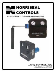
<strong>Norriseal</strong> has been a leader in providing quality level<br />
measurement devices to the petroleum market for over<br />
55 years. In addition to the petroleum market, <strong>Norriseal</strong><br />
level products serve the marine, steel, and industrial<br />
markets.<br />
This brochure describes the <strong>Series</strong> 1001, the 1001A,<br />
and the 1001XL Liquid Level Controllers.The <strong>Series</strong><br />
1001 and 1001A can be right-hand or left-hand mounted<br />
while the 1001XL is used where back-mounting is<br />
preferred.<br />
<strong>Series</strong> 1001<br />
The economical <strong>Series</strong> 1001 Level Controller uses a<br />
non-weatherproof case/cover.<br />
<strong>Series</strong> 1001A<br />
The <strong>Series</strong> 1001A Level Controller uses a weatherresistant<br />
sealed case and a manifold-style pilot<br />
assembly<br />
<strong>Series</strong> 1001XL<br />
The <strong>Series</strong> 1001XL Level Controller offers the features<br />
of a <strong>Series</strong> 1001A, but with a back-mount connection.<br />
Features<br />
No-bleed Pilots. The pneumatic<br />
controller can be equipped with<br />
one of three types of no-bleed<br />
pilots: a snap pilot, throttling<br />
pilot, or patented Envirosave<br />
pilot.<br />
Removable Door. The controller<br />
door can only be<br />
removed after opening 90°. This<br />
feature prevents the door from<br />
vibrating loose while in the<br />
closed position. A lever latch<br />
keeps a positive engagement<br />
between the case and the door.<br />
Weather-resistant Sealed<br />
Case (1001A & 1001XL). An O-<br />
ring gasket seals internals from<br />
outside weather and allows the<br />
harmful exhaust gases to<br />
be vented to a remote area by<br />
tubing the vent connection to<br />
an exhaust manifold.<br />
Built-In Filter. A built-in 40-<br />
micron stainless steel filter in the<br />
gas supply connection reduces<br />
required maintenance of the<br />
controller’s pilot.<br />
Contents<br />
2 Design<br />
3 Principle of Operation<br />
4 Performance<br />
Characteristics<br />
5 Materials<br />
6 How to Order<br />
7 Model Code: Level<br />
Controllers<br />
8 Dimensions<br />
10 Vertical Chambers<br />
12 Domes and Horizontal<br />
Chambers<br />
13 Model Code: Vertical<br />
Chambers and Domes<br />
14 Model Code:<br />
Horizontal Chambers<br />
15 Applications
2<br />
Features (continued)<br />
Interface Control. A wide spring range makes<br />
the control of a liquid interface possible with the<br />
standard displacer.<br />
Marine Service. Stainless steel internals are<br />
available.<br />
Field-Reversible Action.This adjustment<br />
determines whether rising liquid level will<br />
increase or decrease pilot output.<br />
Right- or Left-Hand Mount (1001 & 1001A).<br />
The controller may be changed for right-hand or<br />
left-hand mount in the field without additional parts.<br />
Design<br />
Snap Pilot<br />
The pilot is comprised of two valves –<br />
one to admit pilot pressure, and one<br />
A to exhaust pressure.<br />
Ball “A”controls the flow of gas into<br />
the pilot and is held closed with force<br />
B exerted by supply pressure on the<br />
seating area of the ball.<br />
When the force transmitted to thrust<br />
Snap Pilot<br />
pin “B” is sufficient to overcome the<br />
force holding Ball "A" seated, "A" snaps upward<br />
allowing gas to flow past “A” and out the side port<br />
of the pilot.<br />
The spherical end of thrust pin “B” closes the<br />
exhaust port the instant ball "A” snaps upward.<br />
The exhaust port seating area is smaller than the<br />
seating area of the supply port; therefore, the push<br />
rod must remain seated against supply pressure<br />
until force on the rod diminishes.<br />
A simultaneous action occurs as force is removed<br />
from thrust pin “B”. Pilot pressure opens the<br />
exhaust port by unseating the push rod, and supply<br />
pressure forces ball “A” to close the supply<br />
port. The difference in seating area gives this pilot<br />
Snap-Action.<br />
Throttling Pilot<br />
D<br />
C<br />
H<br />
Throttling E<br />
Pilot<br />
Two valves are used to admit and<br />
exhaust pressure. A diaphragm “E”<br />
used in cooperation with the valves<br />
creates a Force-Balance Pilot.<br />
The pilot output pressure acts upon<br />
the diaphragm so that the diaphragm<br />
pushes back with the same force<br />
being applied by the push rod. These<br />
balanced forces are the reason for the<br />
term “Force-Balance.”<br />
Electric Controller. This option utilizes a<br />
standard electric switch; SPDT or DPDT.<br />
Split Displacer. For liquid dump spans greater than<br />
the standard displacers can provide, a<br />
split displacer can give dump spans up to 70<br />
feet in length.<br />
NACE. All controllers can be configured to meet<br />
NACE MR0175-2002 specifications.<br />
The throttle pilot works in the same manner as the<br />
snap pilot except the output pressure is proportioned<br />
to the amount of force applied to the push<br />
rod. More force on the rod produces a proportionate<br />
increase in pilot pressure.<br />
When the push rod force changes, the pilot seeks<br />
a new balance point by either exhausting the output<br />
loading at valve “C” or unseating valve “D” to<br />
increase output loading. Instrument gas does not<br />
flow while the pilot is in balance.<br />
EnvirosavePilot<br />
F<br />
G<br />
A<br />
H<br />
Envirosave<br />
Pilot<br />
This patented pilot works identically<br />
to the snap pilot. The difference<br />
between the two is the O-ring seals<br />
“F” and “G,” which give a positive<br />
seal to eliminate leakage and prevent<br />
fugitive emissions. The EPA has independently<br />
measured the Envirosave<br />
pilot to have a zero CFH consumption<br />
rate.*<br />
Electric Level Switch<br />
Electric<br />
Switch<br />
The electric level switch<br />
uses the force balance<br />
principle to open and<br />
close an electrical switch<br />
in response to rising or<br />
falling levels. Two standard<br />
switches are available, single pole double<br />
throw (SPDT) or double pole double throw<br />
(DPDT), both with explosion-proof enclosure.<br />
* United States of America. Air and Radiation. Environmental Protection<br />
Agency. Lessons Learned From Natural Gas Star Partners: Options for<br />
Reducing Methane Emissions From Pneumatic Devices in the Natural<br />
Gas Industry. Appendix A. Washington, DC, 2003.
Principle of Operation<br />
3<br />
Force Balance Principle<br />
Theory of Operation<br />
The operation of the <strong>Series</strong> 1001, 1001A, and<br />
1001XL Level Controllers is based on the Force<br />
Balance Principle. The Force Balance Principle states<br />
when an object is submerged in a liquid, it creates<br />
a buoyant force that is proportional to the weight<br />
of the liquid displaced. A <strong>Norriseal</strong> level controller<br />
uses a spring to balance the weight of a displacement-type<br />
element (displacer), eliminating the<br />
need for custom-weighted displacers and floats.<br />
As the displacer is immersed into the liquid, the<br />
amount of force available is proportional to the<br />
weight of the liquid displaced. The result of this<br />
force is transmitted to the controller by a rotational<br />
movement of the shaft. This rotational movement<br />
causes the fulcrum and lever (flapper bar) to push<br />
up the pilot thrust pin. The amount of force is<br />
proportional to the level on the displacer, creating<br />
a desired output signal. This desired output signal<br />
can be a pneumatic on/off signal using a snap<br />
pilot, a pneumatic modulating signal using a<br />
throttle pilot, or an electrical SPDT or DPDT signal<br />
by using an electric micro switch.<br />
Controller Action<br />
Controller action is “Direct Acting” when the<br />
output signal increases as the liquid level rises<br />
on the displacer. In “Reverse Acting,” the output<br />
signal decreases as the liquid level increases on<br />
the displacer.<br />
Proportional Band<br />
Proportional Band or Span is the ratio of the displacer<br />
length used versus the total length of the<br />
displacer to achieve a desired output signal. For<br />
on/off control, the snap pilot output is equal to the<br />
supply pressure over the span of the controller.<br />
The span can be changed by sliding the fulcrum<br />
on the lever. Moving the fulcrum away from the<br />
pilot thrust pin increases the span, and moving<br />
the fulcrum towards the pilot decreases the span.<br />
For throttling control, the output will vary over the<br />
proportional band.<br />
Function of the Adjustable Spring<br />
Not only does the spring balance the weight of<br />
the displacer, it can also be adjusted to shift the<br />
setpoint on the displacer. With spring force held<br />
constant, a higher liquid level on the displacer<br />
produces a larger force available to the pilot.<br />
When the spring force is reduced by decompressing<br />
the spring, a higher liquid level on the displacer<br />
is required to produce the same force as<br />
before. Increasing the spring force by compressing<br />
the spring requires a lower liquid level for the<br />
same force. Thus, increasing/decreasing the spring<br />
force will change the setpoint accordingly.<br />
The spring compression can be reduced further to<br />
a position where a hydrocarbon liquid level will<br />
not produce enough force to produce an output<br />
from the pilot. This makes the control of a liquid<br />
interface possible with the standard displacer. After<br />
the spring is adjusted so the lighter liquid will not<br />
operate the control, there is still adequate spring<br />
force in reserve for the liquid level of heavier liquid<br />
to provide enough force to actuate the pilot.<br />
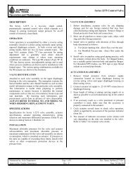
Force Balance Controller<br />
0 PSI PILOT OUTPUT<br />
15 PSI PILOT OUTPUT<br />
Top-level control<br />
0 PSI PILOT OUTPUT<br />
15 PSI PILOT OUTPUT<br />
Liquid interface control
4 Performance Characteristics<br />
PnEumATiC PiLOTS<br />
Output<br />
Proportional, throttle<br />
3–15 psig, 6–30 psig<br />
Differential gap, snap 0–20 psig, 0–30 psig<br />
Differential gap, Envirosave 0–20 psig, 0–30 psig<br />
Supply Pressure Requirement<br />
3–15 psig, 0–20 psig 20–30 psig (min.)<br />
6–30 psig, 0–30 psig 35– 40 psig (min.)<br />
0–50 psig 60 psig (max.)<br />
0–100 psig 100 psig (max.)<br />
Supply and Output Connection 1<br />
⁄4 inch NPT Female<br />
Ambient Temperature<br />
-40° to 180°F (-40° to 82°C)<br />
-40 to 275°F (High temp)<br />
(-40 to 135°C)<br />
Pilot Flow Capacity<br />
Throttle C v 0.394<br />
Snap C v 0.282<br />
EnvirosaveC v 0.282<br />
Proportional Band Adjustment<br />
(Recommended adjustment for<br />
a full output pressure change<br />
over a percent of sensing<br />
element)<br />
Throttle 20–150%<br />
Snap 7– 55%<br />
Envirosave 7– 55%<br />
gEnErAL<br />
Repeatability<br />
1.0% of output span<br />
Dead Band<br />
5.0% of input span<br />
Linearity<br />
1.75% of output span<br />
Ambient Temperature Effect 1.0% @ –40°F (–40°C)<br />
on Setpoint<br />
3.0% @ +170°F (77°C)<br />
Mechanical Disturbance 1.0%<br />
Effects on Setpoint<br />
Specific Gravity<br />
Interface detection 0.035<br />
Top level range 0.35 to 2.00<br />
Temperature Limits<br />
–70° to +600°F<br />
Body process temperature (–57° to 316°C)<br />
(dependent on material selection)<br />
Process Pressure Rating<br />
Beveled - butt weld<br />
To 6000 psig<br />
Threaded (NPT)<br />
To 6000 psig<br />
Grooved<br />
To 2500 psig<br />
Flanged (RF & RTJ)<br />
150 thru 2500 ANSI Class<br />
Union w/sight glass<br />
To 1500 psig<br />
Ambient Temperature -40 to 160°F<br />
(A case extension is used for (–40° to 71°C)<br />
extreme temperatures or<br />
when body insulation is used.)<br />
ELECTriC On/OFF SwiTCh<br />
Output<br />
Proportional band adjustment<br />
(Electric – micro switch)<br />
SPDT 7–55%<br />
DPDT 20–150%<br />
Switch Ratings<br />
SPDT 15 amps at 125, 250,<br />
or 480 V.A.C.<br />
DPDT<br />
10 amps at 125 V.A.C.<br />
Certifications<br />
Explosion proof switch<br />
UL and CSA listed<br />
Class I, Div.1, Groups C&D<br />
Class II, Div.1, Groups E,<br />
F, &G
materials<br />
5<br />
Body<br />
Throttle<br />
Snap<br />
Envirosave<br />
Gasket/diaphragm<br />
Internal Valving<br />
Filter Element<br />
Screws & Nuts<br />
Micro-Switch Enclosure<br />
Junction Box<br />
PnEumATiC PiLOTS<br />
Aluminum<br />
w/Aluminum Seat<br />
Aluminum<br />
w/Aluminum Seat<br />
Aluminum<br />
w/Elastomeric Seat<br />
Nitrile<br />
Nylon<br />
40 Micron SST<br />
SST<br />
ELECTriC On/OFF SwiTCh<br />
Cast aluminum<br />
Cast aluminum<br />
gEnErAL<br />
Body - LLC<br />
1001/1001A ASTM A696/A105<br />
-20 to +600°F (-29 to +316C°)<br />
ASTM A276/A182<br />
-70 to +600°F (-57 to +316C°)<br />
ASTM A351 CF8M/A182<br />
-70 to+600°F (-57 to +316C°)<br />
1001XL<br />
ASTM A216 WCC/A105<br />
-20 to+600°F (-29 to +316C°)<br />
ASTM A216 LCC<br />
-50 to+600°F (-46 to +316C°)<br />
ASTM A351 CF8M/A182<br />
-70 to+600°F (-57 to +316C°)<br />
Hammer Nut<br />
ASTM A105<br />
(where applicable)<br />
Sight Glass<br />
Acrylic -20 to +200°F (-29 to+93C°)<br />
(For special DU/AU<br />
union body)<br />
Displacers<br />
Pyrex -20 to +400°F (-29 to +204C°)<br />
PVC -20 to +140°F (-29 to +60C°)<br />
Acrylic -20 to +200°F (-29 to+93C°)<br />
316 SST-70 to +600°F(-57 to+316C°)<br />
316 SST<br />
316 SST<br />
Displacer Arm<br />
Vertical Hanger<br />
(swivel for vertical<br />
displacer position)<br />
Chain<br />
304 SST<br />
(for vertical extension<br />
and/or split displacer)<br />
Shaft<br />
316 SST -70 to +600°F<br />
(-57 to +316C°)<br />
Bearing Blocks 316 SST -70 to +600°F<br />
(-57 to +316C°)<br />
Bearings<br />
440 SST -70 to +600°F<br />
(-57 to+316C°)<br />
Shaft Seals<br />
Nitrile -20 to +180°F (-29 to +82C°)<br />
Nitrile lo-temp -50 to +180°F<br />
(-46 to +82C°)<br />
Fluorocarbon -20 to +400°F<br />
(-29 to +204C°)<br />
Aflas -20 to +600°F (-29 to +316C°)<br />
EPR -50 to +250°F (-46 to +121C°)<br />
Case & Cover Die cast chromated<br />
aluminum with powder coat<br />
Supply and Output Brass (standard)<br />
Gauges<br />
316 SST<br />
Brass liquid fill<br />
316 SST liquid fill<br />
Torque Bar<br />
Aluminum (standard)<br />
303 SST<br />
Flapper Bar<br />
303 SST<br />
Spring Adjusting Knob Aluminum (standard)<br />
303 SST<br />
Fulcrum<br />
Nylon w/SST screw<br />
Balancing Spring Light-SST w/green marking<br />
Medium-SST w/no marking<br />
Heavy-SST w/yellow<br />
marking<br />
Extra Heavy-SST w/red<br />
marking<br />
Note:<br />
Materials that are certified compatible for NACE service are available upon request.
90<br />
60<br />
30<br />
kPa<br />
PSI<br />
120<br />
210<br />
150<br />
60<br />
30<br />
90<br />
kPa<br />
PSI<br />
120<br />
210<br />
150<br />
60<br />
30<br />
90<br />
kPa<br />
PSI<br />
120<br />
210<br />
150<br />
60<br />
30<br />
90<br />
kPa<br />
PSI<br />
120<br />
210<br />
150<br />
6 how to Order<br />
Determine the model number. This specifies<br />
series and connection size; pilot type; left, right<br />
or back mount; pilot action; seals; and service<br />
condition.<br />
Required Application Information:<br />
A. Fluid media<br />
B. Process temperature (maximum and minimum)<br />
C. Process pressure<br />
D. Vessel size and diameter (distance of connection<br />
from bottom of vessel, any obstructions<br />
that may hinder performance)<br />
E. Body connection type, size, and rating<br />
F. Displacer position (vertical or horizontal)<br />
G. Controller mount (right or left) if applicable<br />
H. Pilot action<br />
I. Area electrical classification if applicable<br />
J. Top level or interface<br />
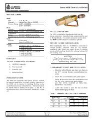
Electric Level Switch<br />
The electric level switch uses the force balance<br />
principle to apply force to a standard Micro-switch.<br />
Two standard switches are available, both with<br />
explosion-proof enclosures: single pole double<br />
throw (SPDT) or double pole double throw<br />
(DPDT). Rating for SPDT switch is 15 amps at 125,<br />
250, or 480 volts A.C. The DPDT switch rating is 10<br />
amps at 125 or 250 volts A.C.<br />
Right-Hand Mount vs. Left-Hand Mount<br />
The <strong>Series</strong> 1001 and <strong>Series</strong> 1001A can be configured<br />
as right-hand mount or left-hand mount.<br />
The orientation of the displacer to the controller<br />
(while facing the front side of the controller)<br />
designates the mounting style. The mounting<br />
can be adjusted in the field. The <strong>Series</strong> 1001XL<br />
back-mount controller is utilized when neither<br />
right-hand or left-hand mounts are practical.<br />
15<br />
10 120<br />
20<br />
15<br />
10 120<br />
20<br />
15<br />
10 120<br />
20<br />
15<br />
10 120<br />
20<br />
5<br />
180 25<br />
30<br />
5<br />
180 25<br />
30<br />
5<br />
180 25<br />
30<br />
5<br />
180 25<br />
30<br />
9 8 7 6 5 4 3 2 1<br />
SENSITIVITY<br />
1 2 3 4 5 6 7 8 9<br />
SENSITIVITY<br />
9 8 7 6 5 4 3 2 1<br />
SENSITIVITY<br />
1 2 3 4 5 6 7 8 9<br />
SENSITIVITY<br />
Right-Hand Mount<br />
Left-Hand Mount
model Code: Level Controllers<br />
7<br />
EnD COnnECTiOnS<br />
Size<br />
Code<br />
1.50” 15<br />
2.00” 2<br />
3.00” 3<br />
4.00” 4<br />
6.00” 6<br />
EnD COnnECTiOnS<br />
Type<br />
Code<br />
Beveled Slip-on BS<br />
Beveled Butt Weld Sch 40 B4<br />
Beveled Butt Weld Sch 80 B8<br />
Beveled Butt Weld Sch 160 B1<br />
Beveled Butt Weld Sch XXH BX<br />
Grooved<br />
GV<br />
Raised Face RF<br />
Flanged Ring Type Joint RJ<br />
Special 4 Bolt SF<br />
Screwed Male NPT SM<br />
Acme Union<br />
AU<br />
Dover Union<br />
DU<br />
PrESSurE rATing<br />
ANSI Rating* Code<br />
150 285 02<br />
300 740 07<br />
600 1480 14<br />
1500 15<br />
2000 20<br />
900 2200 21<br />
3000 30<br />
1500 3750 36<br />
2500 6170 60<br />
*Unit pressure rating subject to selection of<br />
displacer (reference displacer chart below).<br />
2SM60-SRDA-BG<br />
EnCLOSurE<br />
Code<br />
Type<br />
A Standard Case (1001 Only)<br />
G Weather-resistant Case Only<br />
Weather-resistant Case<br />
H<br />
and Piped Exhaust<br />
J<br />
Weather-resistant Case, Piped<br />
Exhaust and Special Marine Internals<br />
K Weather-resistant Case<br />
and Special Marine Internals<br />
SEAL mATEriAL<br />
CODE Max.Temp. (°F)** O-Ring<br />
A 180 Buna<br />
E 250 EPR<br />
F 400 Viton<br />
S 400 Aflas<br />
**Unit temperature rating subject to selection of displacer.<br />
See displacer chart.<br />
Code<br />
D<br />
R<br />
SErViCE COnDiTiOn<br />
Code<br />
B<br />
C<br />
PiLOT ACTiOn<br />
Service<br />
Standard<br />
Vibration<br />
PrESSurE gAugES<br />
Code<br />
Type<br />
- Bronze 0-60 psi (std)<br />
K 316 SST 0-60 psi (1001A/1001XL)<br />
M Liquid Filled 0-60 psi (1001A/1001XL)<br />
Pilot Action<br />
Direct Acting<br />
Reverse Acting<br />
mATEriAL: BODy/ShAFT/BLOCk<br />
Body Shaft Bearing Block Code<br />
A696 CS or WCC 316 316 –<br />
A696 CS (NACE) 316 316 N<br />
316 (NACE) 316 316 R<br />
316 316 316 S<br />
mOunTing CASE<br />
Code Type Mounting<br />
B Back XL Only<br />
L Left Hand<br />
R Right Hand<br />
PiLOT mODE<br />
Mode Type<br />
Electric DPDT (Ex-Proof)<br />
Electric SPDT (Ex-Proof)<br />
EnvirosaveSnap (On/Off)<br />
Pneumatic Snap (On/Off)<br />
Pneumatic Throttle (Modulating)<br />
Code<br />
D<br />
E<br />
B<br />
S<br />
T<br />
DiSPLACEr ChArT<br />
DiSPLACEr TEmPErATurE/PrESSurE rATing<br />
Material Max Temp °F Max Pressure (PSIG)<br />
PVC -20 to 140 6170<br />
Acrylic -20 to 200 6170<br />
SST-2 -70 to 600 2000*<br />
* Higher pressure SST displacers are available.
8 Dimensions<br />
C<br />
F<br />
E<br />
D<br />
G<br />
H<br />
I<br />
A<br />
O<br />
J<br />
K<br />
B<br />
1.25<br />
L<br />
Side view of 1001A<br />
Q<br />
T<br />
I<br />
R<br />
J<br />
P<br />
S<br />
1001A/1001XL<br />
1001<br />
mODEL<br />
1001 1001A 1001XL<br />
A 7.68 8.74 8.74<br />
B 3.00 3.85 3.00<br />
C 4.09 4.13 4.13<br />
D 24.43* 24.43* 24.44*<br />
E 13.67* 13.67* 13.67*<br />
F <br />
G 3.12 4.36 4.36<br />
H 2.75 3.95 3.95<br />
I 0.90 1.90 1.90<br />
J 1.00 2.98 2.98<br />
K 7.68 7.98 7.98<br />
L 4.00 5.19 –<br />
O 6.00 7.13 –<br />
P 7.75 7.85 7.85<br />
Q – 4.00 4.00<br />
R – 7.06 7.06<br />
S – 8.01 8.01<br />
T 1<br />
⁄4 NPT 1<br />
⁄4 NPT 1<br />
⁄4 NPT<br />
U 4.75 4.87 5.16<br />
See page 9 for “F” dimension for different type<br />
of connections<br />
* Using standard 1.88 dia. X 12 inch displacer and<br />
12.5 inch displacer arm. Length is dependent upon<br />
displacer arm and displacer.<br />
G<br />
H<br />
F<br />
F<br />
E<br />
D<br />
Side view of 1001XL
Dimensions<br />
9<br />
DimEnSiOnS “F”<br />
Body Styles X<br />
Body Size<br />
2.00 3.00 4.00 6.00<br />
Beveled B/W SCH 40 6.00 – – –<br />
SCH 80 6.00 – – –<br />
SCH XXH 6.00 – – –<br />
Beveled Slip-on 6.00 – – –<br />
Screwed Male NPT 6.00 – – –<br />
Grooved 6.00 6.88 6.94 7.00<br />
Flanged - 4-bolt -special 6.88 – – –<br />
-150 RF 6.50 6.56 6.56 8.75<br />
-300 RF 6.81 6.75 6.88 9.19<br />
-300 RTJ 7.06 7.00 7.25 9.25<br />
-600 RF 7.19 7.13 7.50 10.13<br />
-600 RTJ 7.25 7.31 7.56 10.19<br />
-900 RF 8.00 9.63 10.13 10.56<br />
-900 RTJ 8.06 9.69 10.19 10.63<br />
-1500 RF 8.00 10.25 10.63 11.88<br />
-1500 RTJ 8.06 10.31 10.69 11.94<br />
-2500 RF 9.13 11.00 11.75 13.50<br />
-2500 RTJ 9.19 11.13 11.94 13.75<br />
F F F F<br />
<strong>Series</strong> 1001 and 1001A<br />
<strong>Series</strong> 1001XL<br />
wEighTS<br />
Body Styles X<br />
Body Size<br />
2.00 3.00 4.00 6.00<br />
Beveled B/W SCH 40 17 NA NA NA<br />
SCH 80 17 NA NA NA<br />
SCH XXH 17 NA NA NA<br />
Beveled Slip-on 18 NA NA NA<br />
Screwed Male NPT 18 NA NA NA<br />
Grooved 8 19 20<br />
Flanged - 4-bolt -special 26 NA NA<br />
-150 RF 25 30 34<br />
-300 RF 27 35 45<br />
-300 RTJ 27 35 45<br />
-600 RF 29 37 55<br />
-600 RTJ 29 37 55<br />
-900 RF 40 51 75<br />
-900 RTJ 40 51 75<br />
-1500 RF 45 72 95<br />
-1500 RTJ 45 72 95<br />
-2500 RF 61 110 150<br />
-2500 RTJ 61 110 150<br />
Weights are for 1001. For 1001A add 1 lb. and for 1001XL add 2 lb.
10 <strong>Series</strong> 1006 Vertical Chambers<br />
The <strong>Series</strong> 1001 and <strong>Series</strong> 1001A can be externally mounted using our <strong>Series</strong> 1006 vertical or horizontal<br />
external chambers. These external chambers provide more stable operation for vessels with internal<br />
obstruction or considerable internal turbulence.<br />
FLAngED<br />
Style “AA” Style “AB” Style “EE” Style “EF”<br />
nPT<br />
4.11<br />
17.56<br />
1.00 NPT VENT<br />
4.11<br />
17.56<br />
1.00 NPT VENT<br />
4.11<br />
17.56<br />
1.00 NPT VENT<br />
4.11<br />
17.56<br />
8.75<br />
3.88<br />
6.41 MAX<br />
8.75<br />
3.88<br />
6.41 MAX<br />
8.75<br />
3.88<br />
6.41 MAX<br />
8.75<br />
3.88<br />
6.41 MAX<br />
7.00<br />
14.25<br />
7.00<br />
14.25<br />
7.00<br />
14.25<br />
7.00<br />
14.25<br />
1/2 DISPLACER<br />
A<br />
1/2 DISPLACER<br />
B<br />
5.00<br />
1/2 DISPLACER<br />
E<br />
5.25<br />
1/2 DISPLACER<br />
F<br />
5.25<br />
1.00 NPT DRAIN<br />
P<br />
4.00<br />
P<br />
1.00 NPT DRAIN<br />
P<br />
Style “CC” Style “CD” Style “GG” Style “GH”<br />
4.11<br />
17.56<br />
4.11<br />
17.56<br />
4.11<br />
17.56<br />
4.11<br />
17.56<br />
8.75<br />
3.88<br />
1/2 DISPLACER<br />
C<br />
8.75<br />
3.88<br />
1/2 DISPLACER<br />
D<br />
8.75<br />
3.88<br />
1/2 DISPLACER<br />
6.41 MAX<br />
G<br />
5.25<br />
8.75<br />
3.88<br />
1/2 DISPLACER<br />
2.84<br />
6.41 MAX<br />
H<br />
5.25<br />
5.00<br />
1.00 NPT DRAIN<br />
P<br />
1.00 NPT DRAIN<br />
P<br />
Style “EA”<br />
Style “AE”<br />
4.11<br />
17.56<br />
1.00 NPT VENT<br />
4.11<br />
17.56<br />
1.00 NPT VENT<br />
8.75<br />
3.88<br />
6.41 MAX<br />
8.75<br />
3.88<br />
6.41 MAX<br />
7.00<br />
14.25<br />
7.00<br />
14.25<br />
A<br />
A<br />
1/2 DISPLACER<br />
1/2 DISPLACER<br />
5.25<br />
5.25<br />
1.00 NPT DRAIN<br />
P<br />
1.00 NPT DRAIN<br />
P<br />
Other process connections available
<strong>Series</strong> 1006 Vertical Chambers<br />
11<br />
PrOCESS COnnECTiOnS DimEnSiOnS (inChES)<br />
Type Style Displacer Dim** Dim<br />
AA<br />
14<br />
14<br />
A<br />
32 32<br />
AB<br />
14<br />
19<br />
B<br />
32 37<br />
Flanged AE<br />
14<br />
14<br />
E<br />
32 32<br />
CC<br />
14<br />
21<br />
C<br />
32 39<br />
CD<br />
14<br />
26<br />
D<br />
32 44<br />
EA<br />
14<br />
14<br />
A<br />
32 32<br />
EE<br />
14<br />
14<br />
E<br />
32 32<br />
NPT EF<br />
14<br />
18<br />
F<br />
32 36<br />
GG<br />
14<br />
19<br />
G<br />
32 37<br />
GH<br />
14<br />
23<br />
H<br />
32 41<br />
PrOCESS COnnECTiOnS (inChES)<br />
ANSI Class DIM 150 300 600<br />
3.00 x RF P 5.62 5.88 6.19<br />
1.50 flg RTJ P 5.88 5.62 6.19<br />
3.00 x<br />
2.0 flg<br />
4.00 x<br />
1.50 flg<br />
4.00 x<br />
2.0 flg<br />
RF P 5.88 6.12 6.50<br />
RTJ P 6.12 6.44 6.56<br />
RF P 6.12 6.38 6.69<br />
RTJ P 6.38 6.62 6.69<br />
RF P 6.38 6.62 7.00<br />
RTJ P 6.62 6.94 7.06<br />
NPT Size DIM 1.0 in. 1.5 in. 2.0 in<br />
3.00 x NPT P 3.12 3.19 3.31<br />
4.00 x NPT P 3.62 3.69 3.81<br />
**Other displacer lengths available on request.<br />
**Charted dimensions are for process connecting piping.<br />
All other dimensions may vary with respect to flange size<br />
and ANSI class.<br />
Position of Process Connections<br />
The following diagram illustrates the location<br />
of the process connections and level controller<br />
relative to Position 1 (P1) which is zero. Refer<br />
to Model Code, Position Process Connection on<br />
page 13.<br />
P4<br />
P7<br />
P8<br />
LEFT<br />
RIGHT<br />
P3<br />
P1<br />
LEFT<br />
RIGHT<br />
P2<br />
Level Controller<br />
P6<br />
Level Controller<br />
P5
12 Domes and horizontal Chambers<br />
<strong>Series</strong> 1006D Dome<br />
To specify a dome only (this is the top of the<br />
vertical chamber), add a suffix letter ‘D’ to the end<br />
of the <strong>Series</strong> Number. Refer to the Model Code,<br />
Vertical Dome Style on page 13.<br />
17.56<br />
1.0 NPT VENT<br />
3.91<br />
5.88<br />
3.00<br />
6.41 MAX<br />
5.06<br />
G<br />
<strong>Series</strong> 1006 horizontal Chamber<br />
(For Model Code, refer to page 14)<br />
25.75<br />
8.32 13.31<br />
3.0<br />
PROCESS CONNECTION<br />
4.50 6.00<br />
PROCESS CONNECTION<br />
Typical NPT Level Controller & Chamber<br />
(Flanged configuration available)
model Code: Vertical Chambers and Domes<br />
13<br />
ChAmBEr/DOmE PiPE SizE<br />
Description<br />
Code<br />
3.00” (Std.) 3<br />
4.00” 4<br />
VErTiCAL DOmE STyLE<br />
Description<br />
Flanged LLC w/NPT Vent<br />
Flanged LLC w/top Flanged<br />
Process Conn<br />
Screwed LLC w/NPT Vent<br />
Screwed LLC w/Top NPT<br />
Process Conn<br />
DiSPLACEr LEngTh<br />
Description Code<br />
14.00 Inch 14<br />
32.00 Inch 32<br />
48.00 Inch 48<br />
60.00 Inch 60<br />
Dome Only 0<br />
DOmE/ChAmBEr mATEriAL<br />
Code<br />
A<br />
VErTiCAL ChAmBEr STyLE<br />
Type Type Level Process<br />
Process Control Connection Code<br />
Connection Connection Mounting Style<br />
Flanged See Dome Side Top-Side Btm A<br />
Flanged See Dome Side Top-Btm B<br />
Flanged See Dome None-Side Btm C<br />
Flanged See Dome None-Btm D<br />
Screwed See Dome Side Top-Side Btm E<br />
Screwed See Dome Side Top-Btm F<br />
Screwed See Dome None-Side Btm G<br />
Screwed See Dome None-Btm H<br />
1006 Dome Only O<br />
Description<br />
Code<br />
Carbon Steel A105 –<br />
Carbon Steel - NACE, A333/A350 -50°F L<br />
Carbon Steel - NACE, A105/A106 N<br />
316L Stainless Steel - X-Ray NACE R<br />
316L NACE<br />
W<br />
316 Stainless Steel S<br />
PrOCESS COnnECTiOn<br />
Description Code<br />
1.00 Inch 10<br />
1.50 Inch 15<br />
2.00 Inch 20<br />
2.50 Inch 25<br />
3.00 Inch 30<br />
4.00 Inch 40<br />
C<br />
E<br />
G<br />
The following model codes apply to the <strong>Series</strong> 1006 Vertical Chamber<br />
and Dome and to the <strong>Series</strong> 1006D only.<br />
3AA14-20RF 14-P1<br />
POSiTiOn PrOCESS COnnECTiOn<br />
Code<br />
Description<br />
P1 0 Degrees w/LLC at 180 Degrees<br />
P2 90 Degrees w/LLC at 180 Degrees<br />
P3 180 Degrees w/LLC at 180 Degrees<br />
P4 270 Degrees w/LLC at 180 Degrees<br />
P5 45 Degrees w/LLC at 180 Degrees<br />
P6 135 Degrees w/LLC at 180 Degrees<br />
P7 225 Degrees w/LLC at 180 Degrees<br />
P8 315 Degrees w/LLC at 180 Degrees<br />
STuD & gASkET mATEriAL<br />
Code Stud/Nut<br />
Gasket<br />
RF or FF RJ<br />
- ASTM A193-B7/ 316L/GRF CSTL<br />
ASTM A194-2H CSTL GR Solid<br />
A ASTM A193-B8M/ 316L/GRF 316 SS<br />
ASTM A194-8M CSTL GR Solid<br />
B ASTM A193-B7/ 316L/GRF 316 SS<br />
ASTM A194-2H 316SS GR Solid<br />
C ASTM A193-B7/ INC/GRF<br />
ASTM A194-2H CSTL GR<br />
–<br />
D ASTM A193-B8M/ 316L/GRF 316 SS<br />
ASTM A194-SS8M 316SS GR Solid<br />
L ASTM A193-B7M/ INC/GRF 316 SS<br />
ASTM A194-2HM 316SS GR Solid<br />
M ASTM B164/ MON/GRF<br />
Monel 400 316SS GR<br />
–<br />
rATing PrOCESS COnnECTiOn<br />
Code Description<br />
02 150<br />
07 300<br />
Flanged<br />
14<br />
(ANSI)<br />
600<br />
21 900<br />
36 1500<br />
14 NPT (WP) 1480<br />
NOTE:<br />
1. Flanged – LLC & Dome/Chamber connection rated same as<br />
Process Connection. Except - ANSI 150 Class<br />
Dome/Chamber Connection is ANSI 300.<br />
2. Threaded-Dome/Chamber connection is ANSI 600 class;<br />
higher pressure classes available.<br />
Code<br />
RF<br />
RJ<br />
SC<br />
SM<br />
TyPE PrOCESS COnnECTiOn<br />
Description<br />
Flanged - RF (Raised Face)<br />
Flanged - RJ (Ring Type Joint)<br />
Screwed Female<br />
Screwed Male<br />
NOTE:<br />
Specify when Gauge Glass connections are required. Give size,<br />
position, and center-to-center dimensions.
14 model Code: horizontal Chambers<br />
ChAmBEr PiPE SizE<br />
Description<br />
Code<br />
4.00” 4.0<br />
4V12-10SC 30<br />
rATing PrOCESS COnnECTiOn<br />
Code Description<br />
02 150<br />
07 300<br />
Flanged<br />
14<br />
(ANSI)<br />
600<br />
21 900<br />
36 1500<br />
30 NPT (WP) 3000<br />
hOrizOnTAL ChAmBEr STyLE<br />
Type Type Level Process<br />
Process Control Connection Code<br />
Connection Connection Mounting Style<br />
Screwed Flanged Top-Bottom L<br />
Flanged Screwed Top-Bottom M<br />
Flanged Flanged Top-Bottom N<br />
Socket Weld Flanged Top-Bottom S<br />
Screwed Screwed Top-Bottom V<br />
Socket Weld Screwed Top-Bottom X<br />
Buttweld Flanged Top-Bottom Y<br />
Buttweld Screwed Top-Bottom Z<br />
DiSPLACEr LEngTh<br />
Description Code<br />
12.00 Inch 12<br />
Specify XX<br />
Code<br />
RF<br />
RJ<br />
SC<br />
TyPE PrOCESS COnnECTiOn<br />
Description<br />
Flanged - RF (Raised Face)<br />
Flanged - RJ (Ring Type Joint)<br />
Screwed Female<br />
PrOCESS COnnECTiOn<br />
Code Description<br />
10 1.00 Inch<br />
15 1.50 Inch<br />
20 2.00 Inch<br />
ChAmBEr mATEriAL<br />
Description<br />
Code<br />
Carbon Steel A105/A106 –<br />
Carbon Steel - NACE, A105/A106 N<br />
316 Stainless Steel S<br />
316 L Stainless Steel - X-Ray NACE W<br />
Please note: not all available options are shown.
Applications<br />
15<br />
CONTROL<br />
PANEL<br />
PRODUCTION<br />
FLUID IN<br />
SERIES 1001A<br />
HIGH-LEVEL<br />
ALARM<br />
SERIES 1001A<br />
LEVEL<br />
CONTROLLER<br />
SERIES 1001A<br />
LOW-LEVEL ALARM<br />
LIQUID OUT<br />
Common Applications<br />
1. Custody Transfer Measurement Systems<br />
2. Separators<br />
3. Dehydrators<br />
4. Heater Treaters<br />
5. Well Test Systems<br />
6. Interface Detection<br />
7. Compressor Scrubbers<br />
8. Offshore Production Facilities
Why you can depend on<br />
genuine <strong>Norriseal</strong> products<br />
In-house engineering and technical support<br />
In-depth applications experience<br />
Award-winning innovation and ongoing<br />
product development<br />
ISO 9001-certified manufacturing<br />
Over five decades of industry service<br />
Compliance with all industry standards<br />
and specifications<br />
Responsive service and prompt delivery<br />
Field support available worldwide<br />
Please contact your <strong>Norriseal</strong> representative<br />
for more details and assistance in specifying<br />
the optimal solution for your application.<br />
6939 - 68 Avenue NW, Edmonton, <strong>Alberta</strong> T6B 3E3<br />
Phone: (780) 434-8566 • Fax: (780) 434-4267<br />
www.albertaoiltool.com<br />
Due to the continuous improvement program at <strong>Norriseal</strong>, specifications and/or prices are subject to change without notice or obligation.<br />
Envirosave is a mark of <strong>Norriseal</strong>, A Dover Company. All other trademarks contained herein are the property of their respective owners.<br />
©2012 <strong>Norriseal</strong>, A Dover Company<br />
0LLC-0412T-AOT