Opperations Manual 2275 - Alberta Oil Tool
Opperations Manual 2275 - Alberta Oil Tool
Opperations Manual 2275 - Alberta Oil Tool

Create successful ePaper yourself
Turn your PDF publications into a flip-book with our unique Google optimized e-Paper software.
Operation and Maintenance<br />
Series <strong>2275</strong> Control Valve<br />
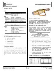
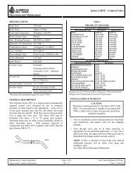
DESCRIPTION<br />
The Series 1-<strong>2275</strong> is a two-way, single seated,<br />
pneumatically operated control valve which responds to a<br />
change in sensing instrument output pressure for on-off<br />
control of relatively clean fluids.<br />
OPERATION<br />
Valve operation is accomplished by either a reverse acting<br />
(normally closed) or a direct acting (normally open) springopposed<br />
diaphragm actuator. In both reverse and direct<br />
acting modes, there are two (2) basic actuator types. The<br />
type 9AA actuator (Style "T") has provision for spring<br />
adjustment and is generally used where shut-off<br />
requirements may change or where exact operating<br />
conditions are unknown. The type 9B actuator (Type "R" &<br />
"D") has factory preset, non-adjustable springs and is used<br />
where process conditions are known and in installations with<br />
limited space. The various spring combinations available for<br />
the 9B actuator are shown in the brochure.<br />
VALVE IDENTIFICATION<br />
Attached to each valve assembly on the upper diaphragm<br />
housing is the valve nameplate. The nameplate contains the<br />
Serial Number and the valve Model Number as well as other<br />
useful information unique to that particular valve assembly.<br />
The information is useful when preparing to perform<br />
maintenance or repairs because it identifies the internal<br />
components such as trim size, trim material, bonnet type and<br />
seal materials. By knowing such information, part<br />
procurement can be done in advance of valve disassembly.<br />
ALWAYS REFER TO SERIAL NO. AND MODEL NO.<br />
WHEN ORDERING REPLACEMENT PARTS.<br />
SPECIFICATIONS<br />
Specifications for Series 1-<strong>2275</strong> valve assembly, actuator<br />
specifications, actuator operating characteristics, spring<br />
selection and maximum differential pressures (Delta P) are<br />
shown in catalog Section 2, Bulletin 2-8.<br />
INSTALLATION<br />
Maximum allowable pressures for the valve and actuator<br />
sub-assemblies and maximum allowable pressure at<br />
maximum temperature for the valve sub-assembly are shown<br />
on nameplate, which is mounted on actuator. If pressures to<br />
the units are capable of exceeding these limits, install relief<br />
valves or other overpressure protection devices in the<br />
pressure lines.<br />
VALVE SUB-ASSEMBLY<br />
1. Before installation, examine valve for any shipping<br />
damage and for any foreign material that may have<br />
collected during crating and shipment. Remove flange or<br />
thread protectors from body end connections.<br />
2. Blow out all pipelines to remove pipe scale, chips, weld<br />
slag and other foreign materials.<br />
3. Install valve in pipeline with direction of flow through<br />
body determined as follows:<br />
i) For Quick Opening trim - direct flow over the seat.<br />
ii) For Modified Percent trim - direct flow under the<br />
seat.<br />
4. Install valve in pipeline using good piping practice, with<br />
the actuator vertical above the body. For flanged bodies,<br />
use a suitable gasket between body and pipeline flanges.<br />
For threaded (NPT) bodies, use TFE tape or pipe thread<br />
sealant on external pipe threads.<br />
ACTUATOR SUB-ASSEMBLY<br />
1. Remove thread protector from actuator supply<br />
connection located on lower diaphragm housing on<br />
reverse acting valves and upper diaphragm housing on<br />
direct acting valves.<br />
2. Connect actuator air supply to .25-18 NPT connection on<br />
diaphragm housing.<br />
3. Keep length of tubing or piping carrying supply air as<br />
short as possible to avoid transmission lag in the control<br />
signal.<br />
4. If an accessory (such as a valve positioner or pressure<br />
controller) is used, make sure that the accessory is<br />
properly connected to the actuator.<br />
5. Cycle actuator several times to check valve operation,<br />
which is signified by movement of the position indicator<br />
(Item 26).<br />
6. The amount of indicator movement (valve stroke) will<br />
vary depending on the trim size installed in the valve.<br />
Refer to Table 1 for nominal valve stroke.<br />
Maintained by: Sales Department Page 1 of 8 Doc. Name: OpMain<strong>2275</strong>.doc<br />
Approved by: Quality Department Rev.: E Date: 26-Mar-04
Series <strong>2275</strong> Control Valve<br />
Operation and Maintenance<br />
MAINTENANCE<br />
WARNING<br />
To avoid personal injury or damage to property from sudden<br />
release of pressure or uncontrolled process fluid, before<br />
beginning disassembly:<br />
1. Isolate the valve from the process.<br />
2. Release captured process pressure.<br />
3. Vent actuator supply pressure.<br />
4. Relieve all actuator spring compression.<br />
The maintenance instructions are divided into three sections:<br />
"9AA Reverse Actuator", "9B Director Actuator" and<br />
"Valve Sub-Assembly".<br />
Each section describes how the actuator or valve subassembly<br />
can be completely disassembled and assembled.<br />
When inspection or repairs are required, disassemble only<br />
those parts necessary to accomplish the job; then start the<br />
assembly at the appropriate step. All Item numbers are<br />
keyed to the parts list at the end of this document.<br />
A. TYPE 9AA REVERSE ACTUATOR<br />
1. Disassembly<br />
1.1. Bypass the control valve. Vent actuator supply<br />
pressure to atmospheric and remove tubing or<br />
piping from lower diaphragm housing (Item 16).<br />
1.2. Loosen jam hex nut (Item 20) and unscrew square<br />
head spring adjusting screw (Item 19) a few turns<br />
out of upper diaphragm housing (Item 18) until all<br />
spring compression is relieved. Complete removal<br />
of the screw is not necessary.<br />
1.3. Remove the 12 hex nuts (Item 30) and hex head<br />
screws (Item 29) which bolt together upper and<br />
lower diaphragm housing (Items 18 and 16).<br />
1.4. Lift off upper diaphragm housing (Item 18);<br />
remove upper spring retainer (Item 22) and actuator<br />
springs (Item 23), exposing to (2) jam hex nuts on<br />
end of valve stem (Item 9).<br />
1.5. With two (2) 9/16" open end wrenches, hold the<br />
lower jam hex nut (Item 28) firmly in place on top<br />
of the lock washer (Item 29) and unscrew upper<br />
jam hex nut (Item 28) from end of valve stem (Item<br />
9).<br />
1.6. Grasp outer edges of diaphragm plate (Item 21) and<br />
lift upward to the open position thereby gaining<br />
access to lowermost remaining hex nut (Item 28),<br />
located against underside of lower bearing washer<br />
(Item 25). Insert a 9/16" open-end wrench between<br />
underside of diaphragm and flange of lower<br />
diaphragm housing (Item 16) and hold hex nut in<br />
place. Unscrew remaining upper jam nut from end<br />
of valve stem (Item 9).<br />
1.7. Remove lock washer (Item 29); lower spring<br />
retainer (Item 24), upper bearing washer (Item 25),<br />
diaphragm plate (Item 21), o-ring (Item 27),<br />
diaphragm (Item 17) and lower bearing washer<br />
(Item 25).<br />
1.8. Remove remaining hex nut from valve stem. If hex<br />
nut cannot be removed without the valve stem<br />
turning, thread the two (2) previously removed hex<br />
nuts (Item 28) on end of valve stem and tighten<br />
together to provide a wrench holding surface to<br />
facilitate hex nut removal.<br />
1.9. Mark position of .25-18 NPT supply connection on<br />
outer surface of bonnet. Loosen bonnet lock nut<br />
(Item 10) by inserting a flat bladed screwdriver<br />
against a lost shoulder of nut and hitting end of<br />
screwdriver with a mallet, or loosen bonnet nut by<br />
placing a 2” socket over nut to loosen it. Unscrew<br />
bonnet lock nut from end of bonnet.<br />
1.10. Lift off lower diaphragm housing (Item 16) and<br />
bonnet/housing gasket (Item 32) from end of<br />
bonnet (Item 4).<br />
2. Assembly<br />
2.1. Place bonnet/housing gasket (Item 32) over screw<br />
threads and against shoulder on upper end of<br />
bonnet (Item 4).<br />
2.2. With dished portion facing upward, place lower<br />
diaphragm housing (Item 16) over bonnet threads<br />
and against bonnet/housing gasket (Item 32).<br />
2.3. Align .25-18 NPT actuator supply connection in<br />
lower diaphragm housing with mark made on<br />
bonnet prior to disassembly. If location of air<br />
supply connection was not previously noted, align<br />
supply connection above lower port connection for<br />
globe body valve, or 180 degrees out from upper<br />
port connection for angle body valve. (See "Valve<br />
Sub-Assembly" procedure in the "Installation"<br />
section for valve body port identification.) If valve<br />
body (Item 1) and bonnet (Item 4) are disassembled<br />
at this stage of maintenance, it will be necessary to<br />
thread body and bonnet together hand tight to<br />
determine final orientation of actuator air supply<br />
connection once valve is completely assembled.<br />
2.4. Thread bonnet lock nut (Item 10) onto upper end of<br />
bonnet (Item 4). Tighten lock nut. Check nut<br />
tightness by grasping outer edges of lower<br />
diaphragm housing (Item 16) and trying to turn by<br />
hand. Lower housing will not turn when bonnet<br />
lock is sufficiently tightened.<br />
2.5. Screw hex nut (Item 28) all the way down to thread<br />
run-out.<br />
Maintained by: Sales Department Page 2 of 8 Doc. Name: OpMain<strong>2275</strong>.doc<br />
Approved by: Quality Department Rev.: E Date: 26-Mar-04
Series <strong>2275</strong> Control Valve<br />
Operation and Maintenance<br />
2.6. Place remaining actuator components on the valve<br />
stem (Item 9) in the following order: lower bearing<br />
washer plate (Item 25), diaphragm (Item 17), o-ring<br />
(Item 27), diaphragm plate (Item 21) with dished<br />
portion facing downward, upper bearing washer<br />
(Item 25), lower spring retainer (Item 24) and lock<br />
washer (Item 29).<br />
2.7. Thread one (1) of the remaining jam hex nuts (Item<br />
28) onto the valve stem (Item 9) and make-up<br />
finger tight. Grasp outer edges of diaphragm plate<br />
(Item 21) and lift upward to raise valve stem and<br />
adjoining components to the open position thereby<br />
gaining access to the lowermost installed hex nut<br />
(Item 28), located against underside of lower<br />
bearing washer (Item 25). Insert a 9/16" open end<br />
wrench between underside of diaphragm (Item 17)<br />
and flange of lower diaphragm housing (Item 16)<br />
and hold lower hex nut in place. Tighten upper jam<br />
hex nut to 10 foot-pounds (14 Newton meters)<br />
torque.<br />
2.8. Thread remaining jam hex nut (Item 28) onto valve<br />
stem (Item 9). With a 9/16" open end wrench, hold<br />
the jam nut firmly in place on top of lock washer<br />
(Item 29) and tighten uppermost jam nut to seven<br />
foot-pounds (9-10 Newton meters) torque.<br />
2.9. Grasp outer edges of diaphragm plate (Item 21) and<br />
lift upward to raise valve stem (Item 9) and<br />
diaphragm (Item 17) to the open position. Align<br />
bolt holes in diaphragm with bolt holes in lower<br />
diaphragm housing flange (Item 16) and install the<br />
12 hex head screws (Item 30) upward from the<br />
lower housing with the heads against underside of<br />
lower housing flange.<br />
2.10. Install actuator spring (Item 23) on top of lower<br />
spring retainer (Item 24).<br />
2.11. Apply a small amount of general purpose grease to<br />
adjusting screw bearing surface of upper spring<br />
retainer (Item 22) and install retainer on top of<br />
actuator spring (Item 23) with shoulder side fitting<br />
down into inside diameter of spring.<br />
2.12. Unscrew square head spring adjusting screw (Item<br />
19) and jam hex nut (Item 20) from upper<br />
diaphragm housing (Item 18). Remove jam nut<br />
from screw. Thread nut back onto screw and thread<br />
screw approximately .50" into the threads in upper<br />
diaphragm housing.<br />
2.13. With dished portion facing downward, rotate upper<br />
diaphragm housing (Item 18) and align position<br />
indicator assembly (Item 26) above the .25-18 NPT<br />
supply connection in lower diaphragm housing<br />
(Item 16) and bring diaphragm housing flanges<br />
together. Be careful not to knock spring out of<br />
position. If housing flanges cannot be brought<br />
together, back-out square head spring adjusting<br />
screw (Item 19) slightly from upper diaphragm<br />
housing.<br />
2.14. Install the 12 regular hex nuts (Item 31) on hex<br />
head screws (Item 30). Tighten in a crisscross<br />
pattern to 30 foot-pounds (41 Newton meters)<br />
torque.<br />
2.15. Perform indicator and actuator spring adjustments<br />
in accordance with "Indicator" and "Spring"<br />
procedures in "Adjustments" section.<br />
B. TYPE 9B REVERSE ACTUATOR<br />
1. Disassembly<br />
1.1. Bypass the control valve. Vent actuator supply<br />
pressure to atmospheric and remove tubing or<br />
piping from lower diaphragm housing (Item 16).<br />
1.2. Remove the 12 hex nuts (Item 31) and hex head<br />
screws (Item 30) which bolt together upper and<br />
lower diaphragm housings (Items 36 and 16).<br />
1.3. Lift off upper diaphragm housing (Item 36) and<br />
remove actuator springs (Item 35). Some actuators<br />
will contain two (2) springs, while others will have<br />
four (4), depending on the exact service conditions.<br />
1.4. With two (2) 9/16" open end wrenches, hold the<br />
lower jam hex nut (Item 28) firmly in place on top<br />
of lock washer (Item 29) and unscrew upper jam<br />
hex nut (Item 28) from end of valve stem (Item 9).<br />
1.5. Grasp outer edges of diaphragm plate (Item 21) and<br />
lift upward to raise valve stem to the open position<br />
thereby gaining access to lowermost remaining<br />
upper jam hex nut (Item 28), located against<br />
underside of bearing washer (Item 25). Insert a<br />
9/16" open end wrench between underside of<br />
diaphragm (Item 17) and flange of lower diaphragm<br />
(Item 17) and flange of lower diaphragm housing<br />
(Item 16) and hold hex nut in place. Unscrew<br />
remaining upper jam nut from end of valve stem.<br />
1.6. Remove lock washer (Item 29), lower spring<br />
retainer (Item 34), diaphragm plate (Item 21), o-<br />
ring (Item 27), diaphragm (Item 17) and bearing<br />
washer (Item 25).<br />
1.7. Remove remaining hex nut from valve stem. If hex<br />
nut cannot be removed without the valve stem<br />
turning, thread the two (2) previously removed hex<br />
nuts (Item 28) on end of valve stem and tighten<br />
together to provide a wrench holding surface to<br />
facilitate hex nut removal.<br />
Maintained by: Sales Department Page 3 of 8 Doc. Name: OpMain<strong>2275</strong>.doc<br />
Approved by: Quality Department Rev.: E Date: 26-Mar-04
Series <strong>2275</strong> Control Valve<br />
Operation and Maintenance<br />
1.8. Mark position of .25-18 NPT supply connection on<br />
outer surface of bonnet. Loosen bonnet lock nut<br />
(Item 10) by inserting a flat bladed screwdriver<br />
against a lost shoulder of nut and hitting end of<br />
screwdriver with a mallet, or loosen bonnet nut by<br />
placing a 2” socket over nut to loosen it. Unscrew<br />
bonnet lock nut from end of bonnet.<br />
1.9. Lift off lower diaphragm housing (Item 16) and<br />
bonnet/housing gasket (Item 32) from end of<br />
bonnet (Item 4).<br />
2. Assembly<br />
2.1. Place bonnet/housing gasket (Item 32) over screw<br />
threads and against shoulder on upper end of<br />
bonnet (Item 4).<br />
2.2. With dished portion facing upward, place lower<br />
diaphragm housing (Item 16) over bonnet threads<br />
and against bonnet/housing gasket (Item 32).<br />
2.3. Align .25-18 NPT actuator supply connection in<br />
lower diaphragm housing with mark made on<br />
bonnet prior to disassembly. If location of air<br />
supply connection was not previously noted, align<br />
supply connection above lower port connection for<br />
globe body valve, or 180 degrees out from upper<br />
port connection for angle body valve. (See "Valve<br />
Sub-Assembly" procedure in the "Installation"<br />
section for valve body port identification.) If valve<br />
body (Item 1) and bonnet (Item 4) are disassembled<br />
at this stage of maintenance, it will be necessary to<br />
thread body and bonnet together hand tight to<br />
determine final orientation of actuator air supply<br />
connection once valve is completely reassembled.<br />
2.4. Thread bonnet lock nut (Item 10) onto upper end of<br />
bonnet (Item 4). Tighten lock nut. Check nut<br />
tightness by grasping outer edges of lower<br />
diaphragm housing (Item 16) and trying to turn by<br />
hand. Lower housing will not turn when bonnet<br />
lock is sufficiently tightened.<br />
2.5. Screw jam hex nut (Item 28) all the way down to<br />
thread run-out on valve stem (Item 9). Place<br />
remaining actuator components on the valve stem<br />
in the following order: bearing washer (Item 25),<br />
diaphragm (Item 17), o-ring (Item 27), diaphragm<br />
plate (Item 21) with dished portion facing upward,<br />
spring retainer (Item 34) and lock washer (Item 29).<br />
2.6. Thread one (1) of the remaining jam hex nuts (Item<br />
28) onto the valve stem (Item 9) and make-up<br />
finger tight. Grasp outer edges of diaphragm plate<br />
(Item 21) and lift upward to raise valve stem and<br />
adjoining components to the open position thereby<br />
gaining access to the lowermost installed hex nut<br />
(Item 28), located against underside of bearing<br />
washer (Item 25). Insert a 9/16" open end wrench<br />
between underside of diaphragm (Item 17) and<br />
flange of lower diaphragm housing (Item 16) and<br />
hold lower hex nut in place. Tighten upper jam hex<br />
nut to 10 foot-pounds (14 Newton meters) torque.<br />
2.7. Thread remaining jam hex nut (Item 28) onto valve<br />
stem (Item 9). With a 9/16" open end wrench, hold<br />
the jam nut firmly in place on top of lock washer<br />
and tighten uppermost jam nut to seven foot-pounds<br />
(9-10 Newton meters) torque.<br />
2.8. Grasp outer edges of diaphragm plate (Item 21) and<br />
lift upward to raise valve stem (Item 9) and<br />
adjoining components to the open position. Align<br />
bolt holes in diaphragm with bolt holes in lower<br />
diaphragm housing flange (Item 16) and install the<br />
12 hex head screws (Item 30) upward from the<br />
lower housing with the heads against underside of<br />
lower housing flange.<br />
2.9. Install actuator springs (Item 35) in spring retainer<br />
(Item 34) in combinations of two (2) or four (4). If<br />
only two (2) springs are used, they must be placed<br />
180 degrees apart for proper valve operation.<br />
2.10. With dished portion facing downward, rotate upper<br />
diaphragm housing (Item 36) and align position<br />
indicator assembly (Item 26) above the .25-18 NPT<br />
supply connection in lower diaphragm housing<br />
(Item 16) and bring diaphragm housing flanges<br />
together as close as possible. Be careful not to<br />
knock spring out of position. There will be an<br />
approximate .25" gap between the diaphragm<br />
housing flanges which will result in compression of<br />
the actuator springs once the housings are bolted<br />
together.<br />
2.11. Install the 12 regular hex nuts (Item 31) finger tight<br />
with equal engagement of screws. Gradually<br />
tighten each nut a few turns at a time in a crisscross<br />
pattern bringing diaphragm housing flanges<br />
together evenly. Tighten nuts to 30 foot-pounds<br />
(41 Newton meters) torque.<br />
2.12. Perform indicator adjustment in accordance with<br />
"Indicator" procedures in "Adjustment" section.<br />
Maintained by: Sales Department Page 4 of 8 Doc. Name: OpMain<strong>2275</strong>.doc<br />
Approved by: Quality Department Rev.: E Date: 26-Mar-04
Operation and Maintenance<br />
9BA2 DIRECT ACTUATOR<br />
Assembly of 9BA2 Direct Actuator<br />
1. Repeat steps (2.1) through (2.4.) in section B 2.<br />
Assembly Type 9B Reverse Actuator.<br />
2. Screw jam hex nut (Item #28) 7/8” down from top of<br />
valve stem (Item #9). Place remaining actuator<br />
components on the valve stem in the following order:<br />
(Item #34) Spring retainer (with two holes)<br />
(Item #35) White spring(two)<br />
(Item #21) Plate diaphragm(dished side down)<br />
(Item #27) O-ring<br />
(Item #17) Diaphragm<br />
(Item #25) Washer bearing<br />
(Item #29) Lock washer<br />
(Item #28) 3/8” Jam nut<br />
3. Using two C-clamps one on each side of stem and<br />
lower housing (Item 16) compress spring down by<br />
tightening clamps until stem sticks through the<br />
diaphragm. Put lock washer (Item 29) and 3/8” jam<br />
nut (Item 28) onto stem then release C-clamps.<br />
4. Using two 9/16” open end wrenches, place one on<br />
3/8” jam nut (Item 28) on top of diaphragm and<br />
inserting the other 9/16” wrench between the<br />
underside of diaphragm plate (Item 21) and flange of<br />
lower diaphragm housing (Item 16) and hold lower<br />
hex nut in place. Tighten upper jam hex nut to 10 ft.<br />
lbs. torque.<br />
5. Repeat steps 2.10 through 2.12 of Section B.2.,<br />
Assembly Type 9B Reverse Actuator.<br />
6. Thread indicator assembly into 1/4” NPT hole on the<br />
bottom housing (Item 16) Using the open end of a<br />
1/4” NPT bull plug, knock the white Teflon ring in the<br />
indicator assembly down to the hex retainer screwed<br />
into the 1/4” NPT hole.<br />
B. VALVE SUB-ASSEMBLY<br />
WARNING<br />
To avoid personal injury or damage to property from sudden<br />
release of pressure or uncontrolled process fluid, before<br />
beginning disassembly:<br />
1. Isolate the valve from the process.<br />
2. Release captured process pressure.<br />
3. Vent actuator supply pressure.<br />
4. Relieve all actuator spring compression.<br />
The maintenance instructions in this section explain the<br />
procedure for trim (plug and seal) removal, inspection,<br />
restoration and installation, which does not require<br />
disassembly of the actuator. These maintenance procedures<br />
Series <strong>2275</strong> Control Valve<br />
assume that the valve body (Item 1) will remain installed in<br />
the pipeline.<br />
1. Trim Removal<br />
1.1. Type 9AA Actuator<br />
(i) Loosen jam hex nut (Item 20) located on top of<br />
upper diaphragm housing (Item 18).<br />
(ii) Turn square head spring adjusting screw (Item<br />
19) out of upper housing until all spring<br />
compression is relieved.<br />
1.2. Type 9B Reverse Actuator<br />
(i) Connect a regulated air supply source to the<br />
lower diaphragm housing (Item 16).<br />
(ii) Pressurize lower diaphragm housing to 30 psig<br />
to raise valve plug (Item 2) to the open<br />
position. Maintain pressurized condition.<br />
1.3. All Actuator Types<br />
(i) With the actuator remaining assembled to the<br />
bonnet (Type 9B Reverse Actuator under<br />
pressure also), unscrew the bonnet (Item 4)<br />
from the valve body (Item 1).<br />
1.4. Type 9AA Reverse Actuator<br />
(i) Turn square head spring adjusting screw (Item<br />
19) into upper diaphragm housing (Item 18)<br />
until valve plug (Item 2) and roll pin (Item 33)<br />
are extended out from lower end of the bonnet<br />
(Item 4).<br />
1.5. Type 9B Reverse Actuator<br />
(i) Vent actuator supply pressure which will<br />
extend valve plug (Item 2) and roll pin (Item<br />
33) from lower end of the bonnet (Item 4).<br />
1.6. All Actuator Types<br />
(i) Drive out roll pin (Item 33) from valve plug<br />
(Item 2).<br />
CAUTION<br />
When removing roll pin (Item 33) and valve plug<br />
(Item 2) use extreme care not to bend valve stem<br />
(Item 9) or scratch hemispherical surface of plug.<br />
(ii) Unscrew valve plug (Item 2) from end of valve<br />
stem (Item 9).<br />
(iii) To remove valve seat (Item 3) and o-ring (Item<br />
12), place 1” socket over seat and loosen it.<br />
Remove it from valve body (Item 1). Remove<br />
o-ring from valve seat.<br />
2. Trim Inspection<br />
2.1. Visually inspect valve plug (Item 2) and seat (Item<br />
3) for signs of erosion, pitting, scratches and<br />
damage from corrosion. A magnifying glass can be<br />
Maintained by: Sales Department Page 5 of 8 Doc. Name: OpMain<strong>2275</strong>.doc<br />
Approved by: Quality Department Rev.: E Date: 26-Mar-04
Operation and Maintenance<br />
Series <strong>2275</strong> Control Valve<br />
helpful in determining the type and severity of any<br />
damage that may be present.<br />
2.2. Fit the plug and the seat together. While looking<br />
into the bottom of the seat, hold the trim set against<br />
a bright light. Any light seen between plug and seat<br />
contact surfaces is indicative of a poor seal.<br />
2.3. Determine the magnitude of any wear or corrosion<br />
damage. Many times the plug and seat contact<br />
surfaces can be fully restored by re-lapping, thereby<br />
extending service life. (See "Trim Restoration"<br />
procedure below.) If damage is too extensive for<br />
restoration, replacement seats, which are lapped,<br />
vacuum tested and ready for installation, are readily<br />
available from the factory.<br />
3. Trim Restoration<br />
3.1. Clean plug and seat in solvent and wipe dry.<br />
3.2. If trim material being restored is 316 stainless steel,<br />
apply a thin coat of 600-grit boron-carbide lapping<br />
compound along the seating diameter of the valve<br />
plug. If trim material is carbide, apply a thin bead<br />
of No. 15 medium grade diamond compound along<br />
the seating diameter of the valve plug. These<br />
compounds are readily available from the factory in<br />
both small and large quantities.<br />
3.3. Fit the plug into the seat and begin lapping by<br />
applying hand pressure to the ends of the parts and<br />
rotating them against each other, reversing the<br />
direction of rotation. A spare valve stem or a 3/8-<br />
24 UNF screw threaded into the end of the plug can<br />
be helpful in holding and rotating the plug against<br />
the seat. Continue lapping trim together stopping<br />
periodically to check results. The length of time<br />
required to restore seating surfaces will depend on<br />
the trim condition prior to lapping. 316 stainless<br />
steel trim will generally require about 3-5 minutes<br />
of lapping if damage is not too severe, whereas<br />
carbide will take about twice as long.<br />
3.4. Valve trim will be sufficiently lapped when the<br />
plug takes on a continuous dull frosty band<br />
extending above and below the seating diameter<br />
with no definite beginning or end to the lapped<br />
area. Stainless steel seats will have an approximate<br />
.03125" wide continuous band around the bottom of<br />
the 30 degree seating angle. Carbide seats will<br />
have an uninterrupted bright appearance around the<br />
bottom of the 30-degree seating angle. If skips or<br />
pits are still present in the lapped seating areas of<br />
the plug or seat, repeat step 3 until satisfactory<br />
results are obtained.<br />
3.5. Wash plug and seat in solvent to remove ALL<br />
lapping compound. Wipe dry.<br />
4. Trim Installation<br />
4.1. Install o-ring (Item 12) in groove of valve seat<br />
(Item 3). Apply a thin coat of general purpose<br />
grease around outside of o-ring.<br />
4.2. Install valve seat (Item 3) into valve body using #1<br />
socket and tighten firmly into valve bridge.<br />
4.3. Type 9AA Reverse Actuator<br />
Turn square head spring adjusting screw (Item 19)<br />
into upper diaphragm housing (Item 18) until roll<br />
pinhole in valve stem (Item 9) is extended from<br />
lower end of bonnet (Item 4).<br />
4.4. Type 9B Reverse Actuator<br />
Vent actuator supply pressure from lower<br />
diaphragm housing (Item 16) which will extend<br />
valve stem (Item 9) and pin hole from end of<br />
bonnet (Item 4).<br />
4.5. All Actuator Types<br />
(i) Thread valve plug (Item 2) onto end of valve<br />
stem (Item 9) engaging the least number of<br />
threads required to align pinholes.<br />
(ii) Using a punch or a drift pin and a mallet, drive<br />
pin into stem/plug junction.<br />
CAUTION<br />
When installing roll pin (Item 32), use extreme care not to<br />
bend valve stem (Item 9) or scratch hemispherical surface of<br />
plug (Item 2). Be certain that roll pin does not extend<br />
beyond outer surface of plug on either side.<br />
4.6. Type 9AA Reverse Actuator<br />
Turn square head spring adjusting screw (Item 19)<br />
out of upper diaphragm housing (Item 18) while<br />
pushing inward on the end of the plug (Item 2) to<br />
retract plug into lower end of bonnet (Item 4).<br />
4.7. Type 9B Reverse Actuator<br />
Pressurize lower diaphragm housing (Item 16) to 30<br />
psig which will retract plug (Item 2) into lower end<br />
of bonnet (Item 4).<br />
4.8. All Actuator Types<br />
(i) Apply a thin coat of general purpose grease<br />
around outside of bonnet o-ring (Item 13).<br />
(ii) With the actuator remaining assembled to the<br />
bonnet (Type 9B Reverse also under pressure),<br />
screw bonnet (Item 4) into valve body (Item 1).<br />
4.9. Type 9AA Reverse Actuator<br />
Perform actuator spring adjustment in accordance<br />
with "Spring" procedure in "Adjustments" section.<br />
4.10. Type 9B Reverse Actuator<br />
Vent actuator supply pressure from lower<br />
diaphragm housing (Item 16).<br />
Maintained by: Sales Department Page 6 of 8 Doc. Name: OpMain<strong>2275</strong>.doc<br />
Approved by: Quality Department Rev.: E Date: 26-Mar-04
Series <strong>2275</strong> Control Valve<br />
Operation and Maintenance<br />
Maintained by: Sales Department Page 7 of 8 Doc. Name: OpMain<strong>2275</strong>.doc<br />
Approved by: Quality Department Rev.: E Date: 26-Mar-04
Series <strong>2275</strong> Control Valve<br />
Operation and Maintenance<br />
Maintained by: Sales Department Page 8 of 8 Doc. Name: OpMain<strong>2275</strong>.doc<br />
Approved by: Quality Department Rev.: E Date: 26-Mar-04